


ID SOLUTECH / CNC MACHINING
PRODUCT BRIEF · CNC 04
플랜지 슬리브 너트
Flanged sleeve nuts
가는 원통 몸통과 원형 플랜지를 갖춘 암나사 부품입니다. 중앙의 나사 홀과 몸통 끝단의 슬롯을 함께 확인할 수 있습니다. 암나사 유효 길이와 몸통·머리의 형상를 중심으로 도면과 조립 조건을 검토합니다.
Slender sleeves combine a circular flange, internal threads and a slot across the body end. Drawing review focuses on usable internal-thread length and sleeve-head geometry.
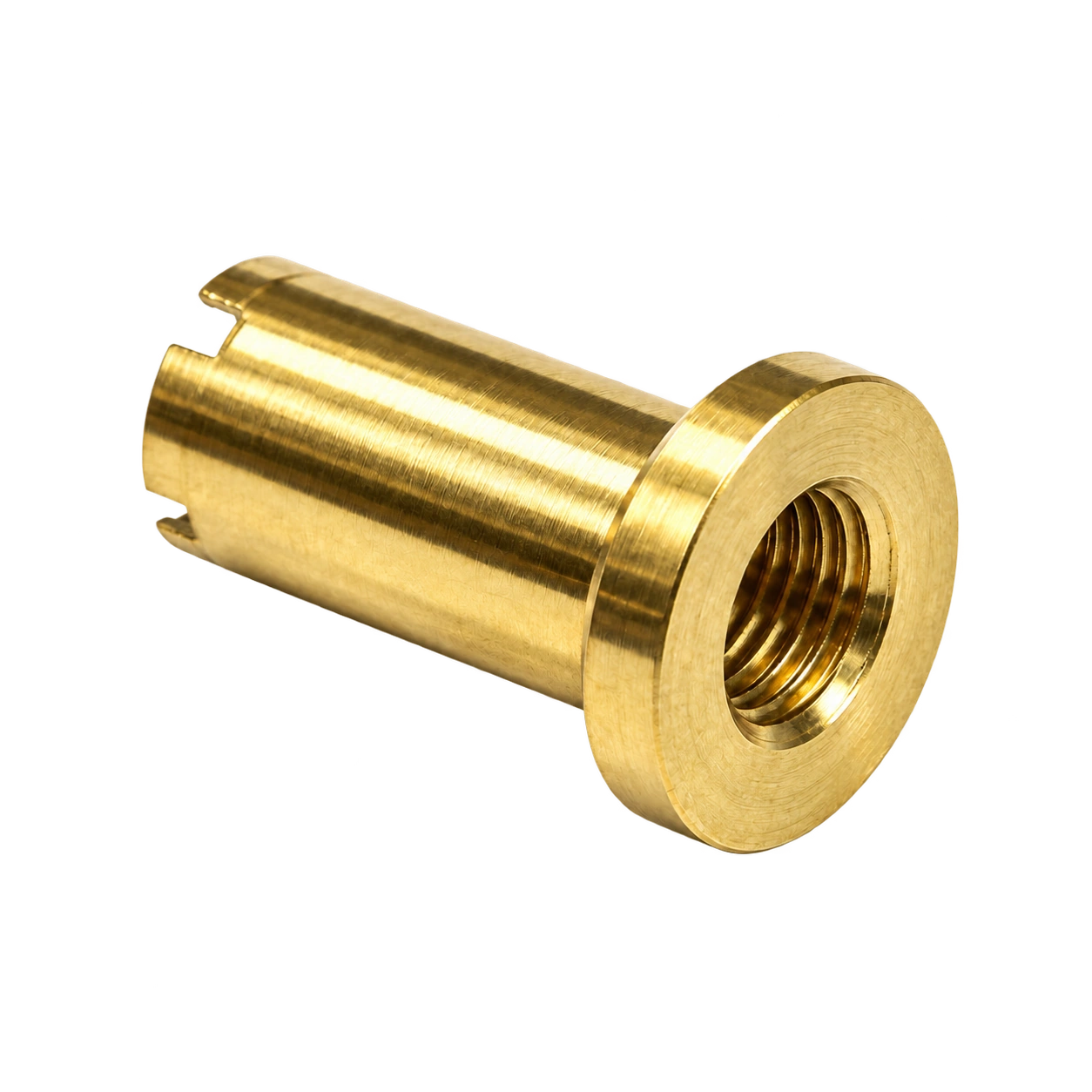
중앙 암나사
Central internal thread
원통 슬리브 몸통
Cylindrical sleeve body
머리와 지지면
Head and seating face
제품 형상과 기능 구간
Geometry & functional features
나사 축과 머리 아래 면을 기준으로 암나사 유효 길이와 몸통·머리의 형상를 나눠 살펴봅니다.
Review usable internal-thread length and sleeve-head geometry from the thread axis and under-head face.
외형과 기능 구간
External geometry
가는 원통 몸통과 원형 플랜지를 갖춘 암나사 부품입니다. 중앙의 나사 홀과 몸통 끝단의 슬롯을 함께 확인할 수 있습니다. 암나사 유효 길이와 몸통·머리의 형상를 중심으로 도면과 조립 조건을 검토합니다.
Slender sleeves combine a circular flange, internal threads and a slot across the body end. Drawing review focuses on usable internal-thread length and sleeve-head geometry.
VISIBLE GEOMETRY
암나사 · 원통 몸통 · 끝단 슬롯
01
중앙 암나사
Central internal thread
중앙 입구 안쪽에 나사산이 형성됩니다. 나사 호칭과 피치, 유효 길이는 입구의 보이는 지름과 별도 항목이며 상대 수나사와 한 쌍으로 검토합니다.
An internal thread lies inside the central opening. Designation, pitch and usable length are separate from the visible entrance diameter and must be reviewed with the mating male thread.
02
원통 슬리브 몸통
Cylindrical sleeve body
나사 주위를 감싸는 원통 몸통은 외경과 길이로 구분합니다. 가장 깊은 내부 형상까지 고려한 남는 벽과, 상대 구멍에 들어가는 외경 구간을 각각 확인합니다.
The sleeve surrounds the thread and is defined by outside diameter and length. Review remaining material around the deepest internal feature separately from the outer insertion region.
03
머리와 지지면
Head and seating face
몸통보다 넓은 머리 형상 아래에는 조립 시 닿는 면이 있습니다. 머리 외곽이 확보하는 공간과 실제 지지면을 구분하고 상대 부품의 모서리·모따기와 간섭을 검토합니다.
A wider head forms an under-head seating face. Distinguish its external envelope from the actual supporting area and review mating edges and chamfers.
04
끝단의 절개 형상
End-slot geometry
원통 몸통의 열린 끝에는 가장자리를 가로지르는 절개가 보입니다. 절개 폭과 깊이, 내부 나사 시작 위치를 함께 검토하고 실제 공구·체결 기능은 도면에서 지정합니다.
Slots cross the rim at the open sleeve end. Review their width and depth alongside thread-entry position; define any tool or fastening function from the drawing.
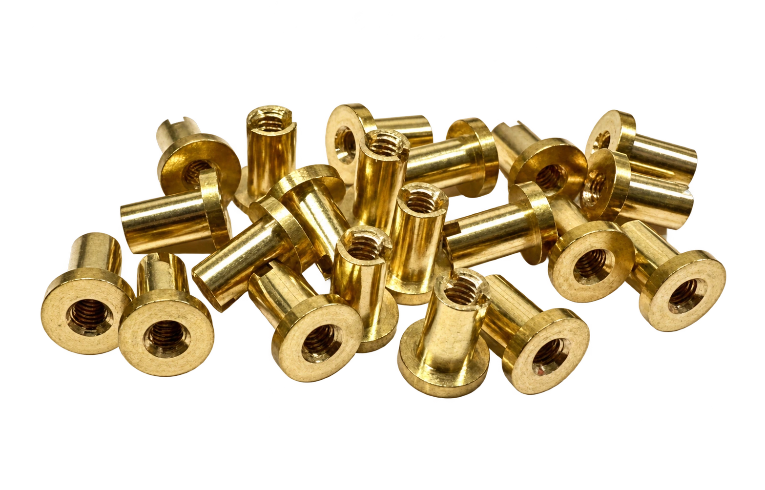
원본에서 확인되는 형상
Source geometry
원본 외관을 바탕으로 한 비례 모델입니다. 실제 치수·공차·소재와 가려진 내부 형상은 승인도면을 따릅니다.
A proportional study of the reference appearance. Production dimensions, tolerances, material and hidden geometry follow the approved drawing.
입체 형상과 설계 항목
3D geometry & design terms
나사 축과 머리 아래 면에서 주요 형상의 위치와 방향을 확인합니다. 기호는 검토 항목을 구분하며 생산 치수를 나타내지 않습니다.
Locate features from the thread axis and under-head face. Symbols identify review dimensions, not production values.
몸통 길이 / Body length
몸통 외경 / Body diameter
머리·플랜지 외경 / Head or flange diameter
머리 두께 / Head thickness
암나사 호칭 / Internal thread designation
암나사 피치 / Internal thread pitch
유효 나사 길이 / Usable thread length
입구 모따기 / Entry chamfer
전체 높이 / Overall height
나사 입구 내공 / Thread entry opening
원본 외관을 바탕으로 한 비례 모델입니다. 실제 치수·공차·소재와 가려진 내부 형상은 승인도면을 따릅니다.
A proportional study of the reference appearance. Production dimensions, tolerances, material and hidden geometry follow the approved drawing.
도면과 제작 사양
Drawing & manufacturing inputs
제품 구분
플랜지 슬리브 너트 / Flanged sleeve nuts
확인 형상
암나사 · 원통 몸통 · 끝단 슬롯
몸통 길이
L · 승인도면 기준
L · Defined by the approved drawing
몸통 외경
D · 승인도면 기준
D · Defined by the approved drawing
머리·플랜지 외경
Df · 승인도면 기준
Df · Defined by the approved drawing
머리 두께
T · 승인도면 기준
T · Defined by the approved drawing
암나사 호칭
M · 승인도면 기준
M · Defined by the approved drawing
암나사 피치
P · 승인도면 기준
P · Defined by the approved drawing
유효 나사 길이
Le · 승인도면 기준
Le · Defined by the approved drawing
입구 모따기
C · 승인도면 기준
C · Defined by the approved drawing
가공 검토와 제조 흐름
Machining route & process planning
형상과 기능면을 기준으로 구성한 가공 검토 흐름입니다. 세부 순서와 공구·고정 방식은 소재, 수량과 도면 조건에 따라 정합니다.
A geometry-led machining review. Sequencing, tooling and workholding depend on material, quantity and drawing requirements.
도면과 기준 확인
Drawing and datum review
나사 축과 머리 아래 면을 기준으로 형상과 조립 조건을 정리합니다. 암나사 유효 길이와 몸통·머리의 형상에 해당하는 치수를 도면에서 구분합니다.
Establish the thread axis and under-head face and identify drawing requirements for usable internal-thread length and sleeve-head geometry.
소재와 공급 상태 검토
Material and stock review
소재 등급과 공급 형상, 후처리 요구를 확인합니다. 절삭 조건은 확정된 소재 자료와 가공 구간에 연결합니다.
Confirm material grade, stock form and finishing requirements; connect machining conditions to approved material data.
물림과 가공 기준 설정
Workholding and setup
나사 축과 머리 아래 면이 공정 중 이어지도록 물림 위치와 공구 접근을 검토합니다. 가공면과 지지면이 겹치는 구간은 재물림 순서에 반영합니다.
Plan workholding and access while maintaining the thread axis and under-head face; account for surfaces unavailable in the initial setup.
외경·머리 형상 가공
Machine sleeve and head geometry
초기 형상에서 가공 기준을 확보하고 필요한 면과 단차를 구분합니다. 소재를 잡는 위치와 가공 후 남는 형상을 함께 검토합니다.
Establish the machining reference and identify required faces and shoulders, considering workholding and the remaining geometry.
나사 기초 홀 가공
Machine the thread preparation bore
도면의 위치 기준에 맞춰 가공 범위를 정하고 공구가 접근하는 방향을 확인합니다. 연결부의 간섭과 남는 단면을 함께 살펴봅니다.
Define the machining extent from drawing datums and review tool direction, transition access and remaining sections.
암나사 형성
Produce internal threads
주요 기능 형상의 크기와 위치, 유효 길이를 정리합니다. 상대 부품과 연결되는 구간은 도면의 조립 요구에 맞춰 검토합니다.
Define the size, position and usable extent of functional geometry and relate the interface to assembly requirements.
입구·끝단 마무리
Finish entry and end features
마지막 가공으로 형성되는 면과 입구·끝단의 버를 확인합니다. 모서리 마무리 범위와 최종 치수 판정 상태를 연결합니다.
Check final faces and residual burrs at entrances or ends and connect edge-finishing requirements with the final inspection condition.
치수 확인과 식별
Verification and identification
암나사 유효 길이와 몸통·머리의 형상를 승인도면의 검사 항목과 연결해 확인합니다. 측정 위치와 기준, 적용된 도면 개정 정보를 함께 기록합니다.
Verify usable internal-thread length and sleeve-head geometry against the inspection plan and record measurement references and drawing revision.
형상을 구현하는 가공 기술
Machining & verification methods
암나사 유효 길이와 몸통·머리의 형상를 만드는 공정과 형상을 확인하는 검사를 연결합니다.
Connect the operations and inspections used to establish usable internal-thread length and sleeve-head geometry.
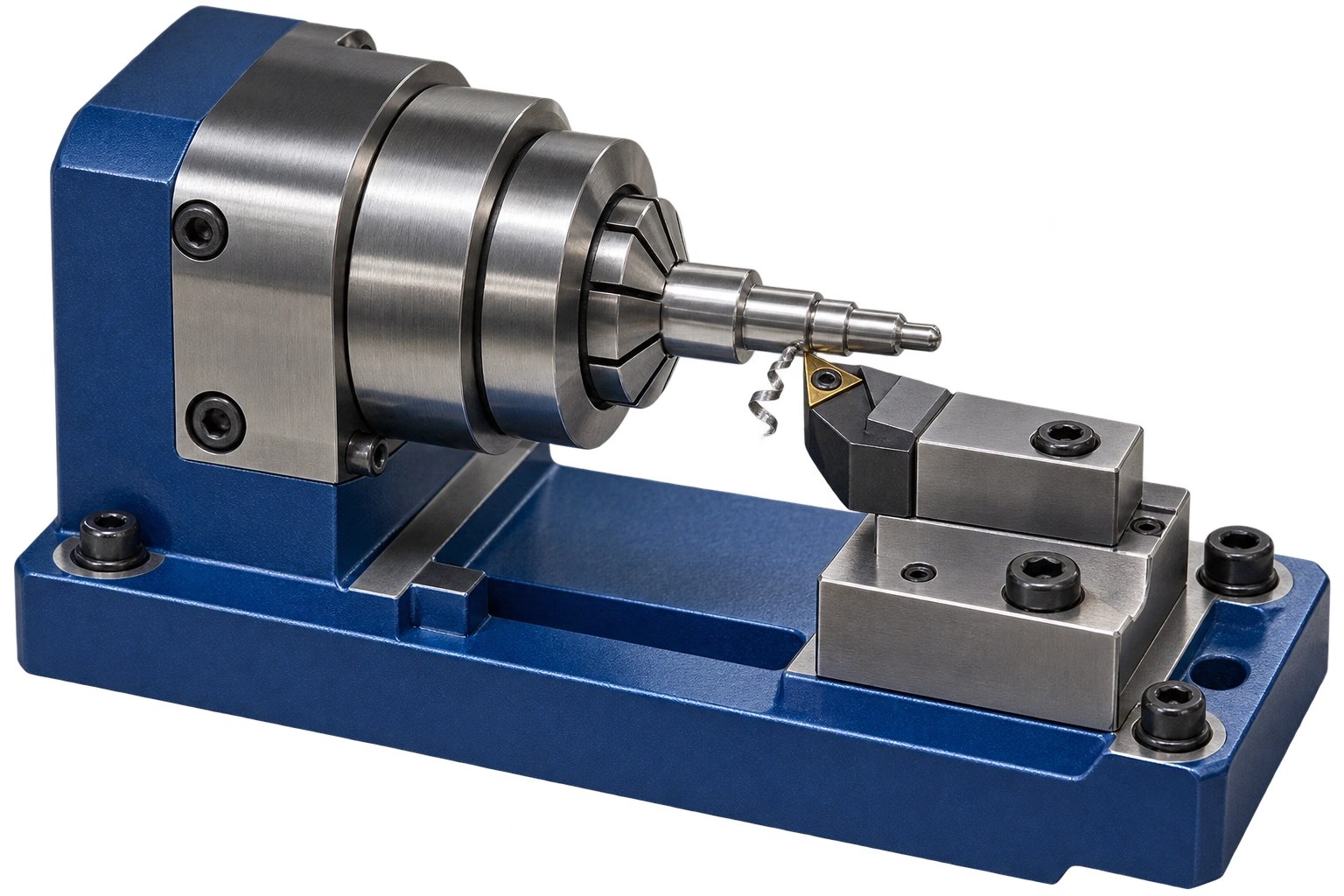
01
외경과 단차 가공
Profile turning
나사 축과 머리 아래 면을 유지하며 외경 구간과 숄더의 위치를 검토합니다. 돌출 길이와 지지 조건, 연결부의 공구 접근을 함께 확인합니다.
Maintain the thread axis and under-head face while reviewing diameter regions and shoulders, including overhang, support and access.
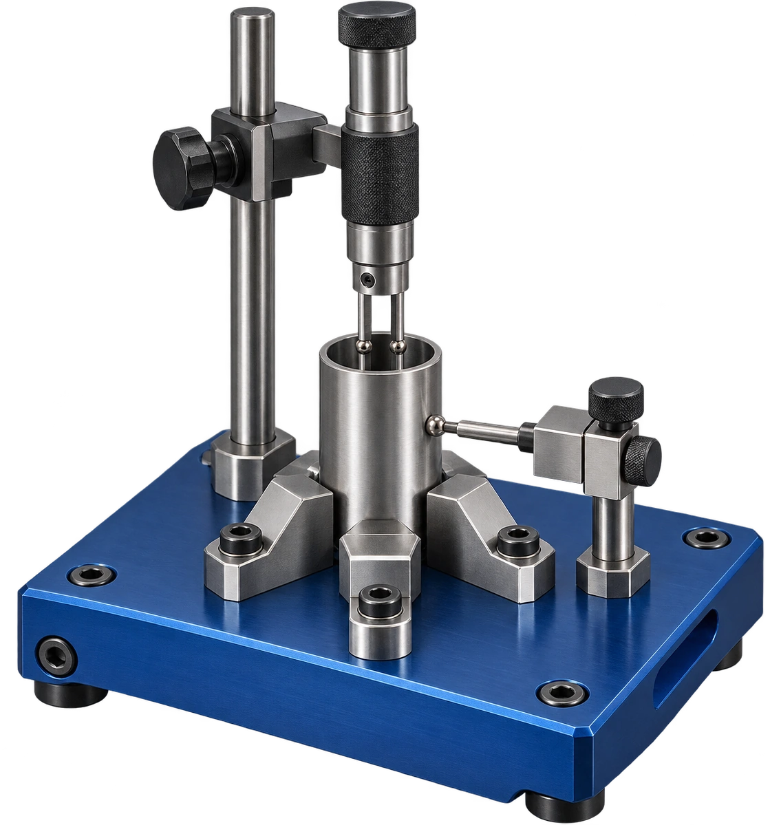
02
내경과 개구 확인
Bore measurement
내경과 개구는 외경과 별도의 측정 항목으로 정리합니다. 깊이와 방향별 측정 위치를 지정하고 접근 가능한 게이지와 측정 방식을 검토합니다.
Treat bores and openings separately from outside diameters. Specify measurement depths and directions and select accessible methods.
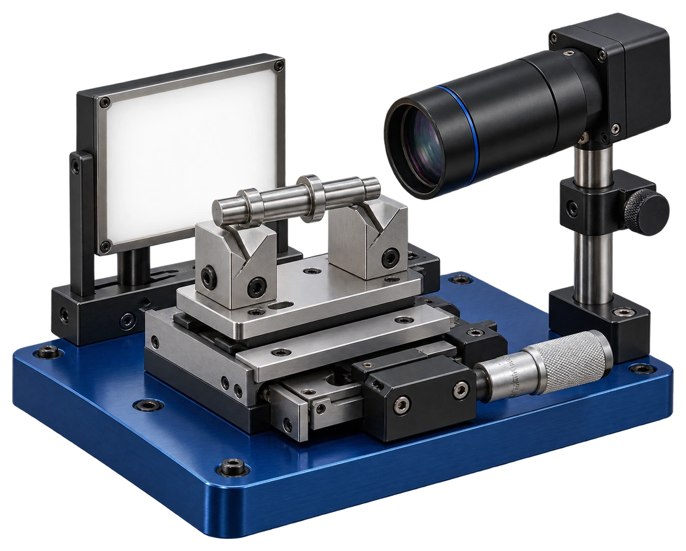
03
윤곽과 위치 확인
Optical profile inspection
암나사 유효 길이와 몸통·머리의 형상를 기준으로 윤곽을 비교합니다. 측정 방향과 기준 위치를 일정하게 하고 필요한 항목은 다른 측정 방식과 함께 확인합니다.
Compare profiles around usable internal-thread length and sleeve-head geometry using consistent views and datums; corroborate critical features with other methods.
공정 이미지는 제작·측정 원리를 설명하는 개념 시각화입니다. 적용 공정과 장비 구성은 승인도면과 제작 조건에 따라 검토합니다.
Process illustrations describe manufacturing and measurement principles. The production route is reviewed against the approved drawing and manufacturing conditions.
상대 부품과 조립 조건
Mating parts & assembly conditions
상대 수나사의 유효 체결 길이와 지지면를 바탕으로 방향, 지지와 조립 여유를 정리합니다.
Review orientation, support and clearance around the effective mating length and supporting face.
ENGINEERING RELATION
나사 피치와 리드
ℓ = n × P
P는 나사 피치, n은 줄 수이며 ℓ은 한 바퀴 회전할 때의 축 방향 리드입니다. 단일 나사산 계열에서는 n = 1입니다.
P is thread pitch, n is the number of starts, and ℓ is axial lead per revolution. For a single-start thread, n = 1.
도면에서 줄 수와 나사 규격을 확인한 경우에 적용합니다. 유효 체결 길이·나사 강도·조임량을 산정하는 식은 아닙니다.
Use only with the specified number of starts and thread form. This does not calculate engagement length, thread strength or tightening displacement under load.
조립 방향
Assembly orientation
상대 수나사의 유효 체결 길이와 지지면를 먼저 정리하고 상대 부품의 기준과 연결합니다. 외관이 비슷해도 실제 맞물리는 구간은 도면으로 구분합니다.
Establish the effective mating length and supporting face and relate it to mating-part datums.
닿는 면과 여유
Seating and clearance
나사 축과 머리 아래 면 주위에서 닿는 면과 비접촉 구간을 나눕니다. 조립 간격과 삽입 깊이는 상대 부품 치수와 함께 검토합니다.
Separate seating and clearance regions around the thread axis and under-head face and review insertion depth with mating dimensions.
조립 후 확인
Post-assembly check
단품 형상과 조립 후 위치 확인을 구분합니다. 필요한 고정 상태와 움직임, 간섭 여부는 실제 조립 조건에서 확인합니다.
Separate part verification from assembly checks and evaluate retention, movement and interference in the intended configuration.
형상과 기능의 관계
Geometry & functional relationships
나사 주위 몸통과 머리 연결부에 연결되는 힘의 경로와 접촉 조건을 검토합니다.
Review load paths and contact conditions around the sleeve surrounding the thread and head transition.
단면의 변화
Section transitions
나사 주위 몸통과 머리 연결부을 중심으로 단면이 달라지는 위치를 확인합니다. 연결부 형상과 남는 단면은 하중 경로에 맞춰 검토합니다.
Review section changes around the sleeve surrounding the thread and head transition and assess remaining geometry against the load path.
접촉과 지지
Contact and support
상대 수나사의 유효 체결 길이와 지지면에서 실제 닿는 면과 지지 범위를 구분합니다. 지름이나 길이 한 항목만으로 조립 상태를 판단하지 않습니다.
Distinguish contact and support regions for the effective mating length and supporting face rather than assessing assembly from one dimension alone.
기능 검증 조건
Functional verification
실제 하중 방향과 반복 동작, 사용 환경을 검토 항목에 연결합니다. 필요한 성능값은 소재와 상대 부품, 시험 조건을 정한 뒤 확인합니다.
Define load direction, repeated operation and environment; establish performance using the specified material, mating parts and test conditions.
ENGINEERING RELATION
중공 원형 단면의 면적
Aₙ = π(Dₒ² − Dᵢ²) / 4
Dₒ는 해당 단면의 바깥지름, Dᵢ는 안지름이며 Aₙ은 동심 원형 중공 단면의 기하학적 면적입니다. 두 지름은 같은 단위로 사용합니다.
Dₒ is the outside diameter and Dᵢ the inside diameter of the same section. Aₙ is the geometric area of a concentric annular section, using consistent units.
모따기·홈·나사·편심·단차가 없는 단면에 적용합니다. 이 값만으로 강도나 실제 접촉 면적을 정하지 않습니다.
Applies to a section without chamfers, slots, threads, eccentricity or steps. Area alone does not determine strength or actual contact area.
소재와 표면 관리
Material & surface requirements
기능면의 요구와 외관 표현을 구분하고 최종 완성 상태를 기준으로 표면 조건을 정리합니다.
Separate functional-surface requirements from appearance and define the final finished condition.
소재와 외관
Material and appearance
색상과 광택은 원본 형상을 표현하는 외관 정보입니다. 제작 소재와 공급 상태는 도면, 소재 규격과 성적서로 구분합니다.
Colour and sheen describe the reference appearance. Define production material and condition through drawings, specifications and certificates.
기능면과 마무리
Functional finish
암나사 유효 길이와 몸통·머리의 형상에 관련된 면의 표면 요구를 구분합니다. 모따기와 버 제거 범위는 형상 치수 및 조립 방향과 함께 지정합니다.
Specify surface requirements for usable internal-thread length and sleeve-head geometry and relate edge finishing to geometry and assembly direction.
후처리와 치수
Treatment and dimensions
표면처리나 열처리가 필요한 경우 적용 범위와 공정 순서를 정리합니다. 최종 검사 기준이 처리 전·후 중 어느 상태인지 구분합니다.
When treatment is specified, define coverage and sequence and identify whether inspection applies before or after treatment.
품질 검토와 원인 구분
Quality review & defect analysis
도면 기준을 측정 위치, 결과 기록과 제품 식별에 연결합니다.
Connect drawing requirements to measurement locations, records and product identification.
도면 개정 관리
Drawing revision
형상과 검사 항목, 소재 조건이 같은 도면 개정을 참조하도록 정리합니다. 변경된 기능면은 재검토 항목으로 구분합니다.
Align geometry, inspection and material requirements with one drawing revision and review changed functional features.
기준 위치 기록
Measurement references
나사 축과 머리 아래 면에서 측정 위치와 방향을 지정합니다. 반복 측정은 같은 지지 조건을 사용하도록 계획합니다.
Specify measurement positions and directions from the thread axis and under-head face and maintain consistent support.
형상과 외관 구분
Geometry and appearance
치수·형상 결과와 표면의 찍힘, 버, 오염을 서로 다른 항목으로 기록합니다. 외관 판정 기준은 사용 부위에 맞춰 정리합니다.
Record geometry separately from dents, burrs or contamination and define appearance criteria for the intended interface.
제품 식별과 보호
Identification and protection
플랜지 슬리브 너트의 형상이 취급과 포장 과정에서 손상되지 않도록 접촉 위치를 검토합니다. 로트와 검사 기록을 연결할 식별 조건을 정리합니다.
Review handling contact points to protect flanged sleeve nuts geometry and connect lot identification with inspection records.
검사 항목과 기록 기준
Inspection characteristics & records
아래 표는 형상별 검사 계획 항목입니다. 측정 방식과 허용 기준은 승인도면에 맞춰 확정합니다.
These are geometry-specific inspection planning items. Final methods and acceptance criteria follow the approved drawing.
검사 특성 / CHARACTERISTIC
측정 접근 / METHOD
기록 기준 / RECORD
몸통 길이
Body length
마이크로미터·높이·영상 측정 검토
Review micrometer, height or optical measurement
승인도면의 몸통 길이 및 연결된 형상·위치 요구
Approved body length and associated form or location requirements
몸통 외경
Body diameter
치수·윤곽 측정 검토
Review dimensional and profile measurement
승인도면의 몸통 외경 및 연결된 형상·위치 요구
Approved body diameter and associated form or location requirements
머리·플랜지 외경
Head or flange diameter
치수·윤곽 측정 검토
Review dimensional and profile measurement
승인도면의 머리·플랜지 외경 및 연결된 형상·위치 요구
Approved head or flange diameter and associated form or location requirements
머리 두께
Head thickness
마이크로미터·높이·영상 측정 검토
Review micrometer, height or optical measurement
승인도면의 머리 두께 및 연결된 형상·위치 요구
Approved head thickness and associated form or location requirements
암나사 호칭
Internal thread designation
규격에 맞는 나사 게이지·측정
Thread gauge or measurement appropriate to the specification
승인도면의 암나사 호칭 및 연결된 형상·위치 요구
Approved internal thread designation and associated form or location requirements
암나사 피치
Internal thread pitch
규격에 맞는 나사 게이지·측정
Thread gauge or measurement appropriate to the specification
승인도면의 암나사 피치 및 연결된 형상·위치 요구
Approved internal thread pitch and associated form or location requirements
유효 나사 길이
Usable thread length
규격에 맞는 나사 게이지·측정
Thread gauge or measurement appropriate to the specification
승인도면의 유효 나사 길이 및 연결된 형상·위치 요구
Approved usable thread length and associated form or location requirements
입구 모따기
Entry chamfer
치수·윤곽 측정 검토
Review dimensional and profile measurement
승인도면의 입구 모따기 및 연결된 형상·위치 요구
Approved entry chamfer and associated form or location requirements
적용 기능과 사용 조건
Functional applications & service conditions
형상에 따른 적용 검토 분야입니다. 실제 사용 적합성은 상대 부품과 요구 성능을 기준으로 확인합니다.
Geometry-based application review areas; confirm suitability against actual mating parts and performance requirements.
슬리브 내부의 나사 연결
Threaded sleeve interfaces
수나사가 슬리브 안으로 들어가는 구조에서는 유효 나사 길이와 끝단 여유가 핵심 검토 항목입니다. 입구의 보이는 지름과 나사 호칭을 구분해 상대 체결구 규격을 연결합니다.
For a screw entering the sleeve, usable thread length and end clearance are key review items. Distinguish visible entrance diameter from thread designation.
머리 아래 면의 지지
Under-head support
머리 또는 플랜지가 판·하우징 면에 닿는 배치에서는 외곽 공간과 지지면을 각각 확인합니다. 몸통 삽입 길이가 상대 홀 깊이와 맞는지도 함께 검토합니다.
Where a head or flange seats on a plate or housing, review both its envelope and supporting face. Compare sleeve insertion length with mating-hole depth.
주변 공간이 제한된 체결
Space-limited fastenings
작은 몸통 안에 나사와 벽이 함께 놓이는 구조이므로 외경, 내부 나사와 주변 부품 간격을 함께 비교합니다. 체결 성능은 형상만으로 정하지 않고 소재·나사 규격·조립 조건으로 검토합니다.
A compact sleeve combines thread and surrounding wall within a limited envelope. Review all interfaces together; fastening performance also requires material, thread and assembly specifications.
도면에서 완성 형상까지
From drawing to finished geometry
플랜지 슬리브 너트의 암나사 유효 길이와 몸통·머리의 형상를 기준으로 가공과 조립·검사를 연결합니다. 검토 도면과 수량, 소재 및 표면 조건을 함께 정리하여 필요한 기능면과 확인 범위를 명확히 합니다.
Connect machining, assembly and inspection through usable internal-thread length and sleeve-head geometry. Review drawing, quantity, material and surface requirements together.
사양 검토에 필요한 자료
Required information
01
최신 개정 2D 도면과 가능한 3D 데이터
02
소재 규격과 공급 상태
03
기준면·기준축과 주요 기능 치수
04
상대 부품의 결합 형상과 조립 방향
05
표면·후처리 및 모서리 마무리 조건
06
수량·검사 기록·포장 조건