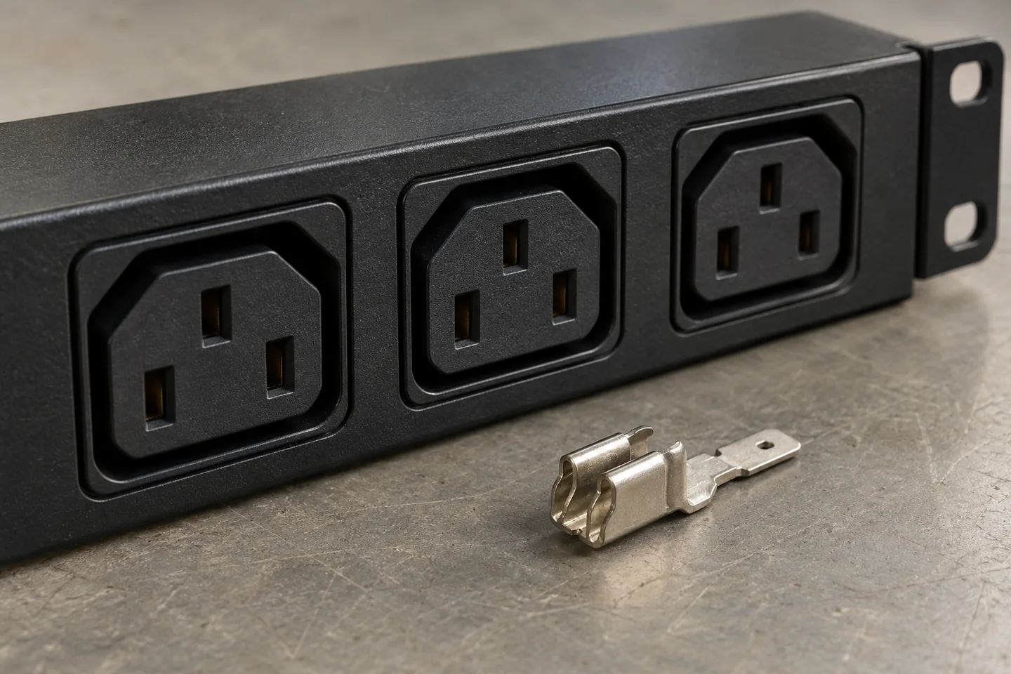
Behind the server racks of a data centre stand power distribution units (PDUs) lined with dozens of outlets. As server density and power rise, every outlet must pass current without interruption. The part that actually does this work is the PDU receptacle contact, the small spring that grips the plug blade inside the outlet.
Enquiries about hot outlets, loose plugs or a discontinued contact usually lead back to one question. How much force presses on the blade, and how long does that force last? This article starts from contact structure and the origin of heat. It then covers materials and plating, progressive-die manufacturing, inspection and approval, and what to prepare for an enquiry.
PDU OUTLETS / C13-style outlets and a separate spring contact
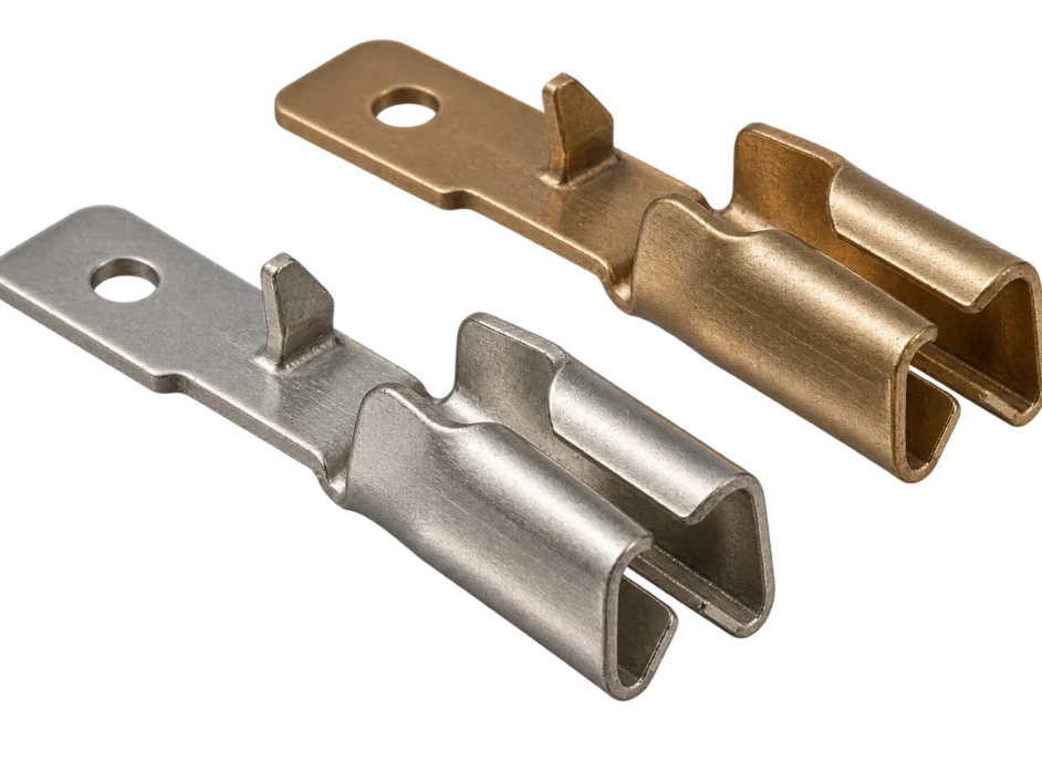
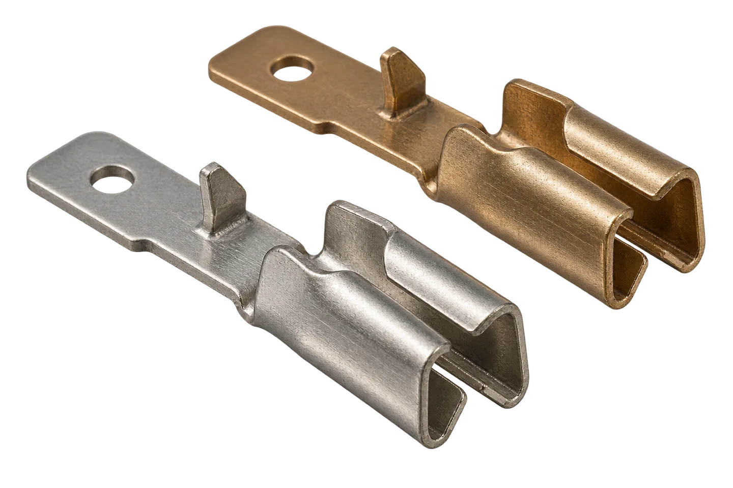
C13- and C19-style PDU outlets commonly used in data centres mate with the corresponding C14- and C20-style blade arrangements. The housing guides the blades and locates the contacts; the metal contacts press against the blades to carry current. This article focuses on a structure with two opposed resilient contact surfaces. The number of beams and the form of the termination tab or crimp barrel depend on the outlet design and internal wiring method.
In the free state, the gap between the two beams is made narrower than the blade thickness. When the blade enters, the beams deflect by the difference, and their tendency to recover presses on the blade surface. This normal force is set by the interference, the beam length, thickness and width, and the elastic modulus of the material. A slightly shorter or thicker beam can change the force considerably at the same interference.
An outward-flared lead-in guides the blade into the contact. Its angle and surface condition affect the initial insertion force and plating wear. Embossed or curved contact surfaces define the intended contact regions, but two contact points alone do not guarantee performance with a tilted blade. Housing support, insertion depth, beam deflection and the remaining contact force must be considered together.
The bend at the beam root carries the highest bending stress at every insertion. If that stress exceeds the elastic range, the beam takes a permanent set. The interference then falls, and the contact works with less force from that point on. The housing retention lance and the tail keep the contact steady inside the housing and connected reliably to the internal conductor.
Mating metal surfaces look broadly in touch, yet metal actually meets metal only at a few small asperities. Current crowding through these spots creates constriction resistance, and oxide or contamination films add film resistance; together they form the contact resistance. Higher normal force flattens the asperities over a larger area and breaks through films more easily, lowering resistance.
Power dissipated at a resistive interface is expressed as I²R. At the same current, greater contact resistance produces more heat, but the resulting temperature rise also depends on contact cross-section, conductor length, housing and heat transfer to the surrounding air. Resistance at the termination tab, crimp or busbar joint must be considered alongside the mating interface to locate the source of heating.
The difficulty is that these effects reinforce one another. Higher temperature accelerates stress relaxation in the spring material and lowers normal force; lower force raises contact resistance, which raises temperature again. On tin-plated surfaces, micromotion from temperature changes and vibration can cause fretting corrosion, increasing resistance in steps.
A PDU may sit at the rear of a rack in warm server exhaust. Relevant conditions include the air temperature at the outlet, simultaneous loading of neighbouring circuits and heating within the internal conductors, rather than only the room setpoint. A coupler pin-temperature classification and a PDU ambient-temperature rating describe different conditions; their numerical difference is not a verified allowance for operating temperature rise. Check the component approval conditions and the ratings and temperature-rise test conditions of the complete PDU separately.
A heavy power cord pulling the plug to one side, or a plug that is not fully inserted, also reduces the contact spots. Outlet heating should therefore not be blamed on a single contact without considering load current, ambient temperature, plug condition and internal connections.
| Factor | What changes at the interface | What to check |
|---|
| Low interference or beam set | Lower normal force, smaller true contact area | Beam gap, insertion and withdrawal force |
|---|
| Stress relaxation at temperature | Contact force falls over time | Alloy grade, re-measurement after heat ageing |
|---|
| Surface films and fretting | Higher film resistance, stepwise resistance rise | Plating type and thickness, voltage-drop trend |
|---|
| Tilted or partly inserted plug | Only one point touches or contact length shrinks | Insertion depth, cord load and retention |
|---|
| Tail and internal conductor joint | Resistance and heat outside the contact | Temperature and resistance at welds or fasteners |
|---|
What changes at the interface · What to check
- Low interference or beam set
- Lower normal force, smaller true contact area
- Beam gap, insertion and withdrawal force
- Stress relaxation at temperature
- Contact force falls over time
- Alloy grade, re-measurement after heat ageing
- Surface films and fretting
- Higher film resistance, stepwise resistance rise
- Plating type and thickness, voltage-drop trend
- Tilted or partly inserted plug
- Only one point touches or contact length shrinks
- Insertion depth, cord load and retention
- Tail and internal conductor joint
- Resistance and heat outside the contact
- Temperature and resistance at welds or fasteners
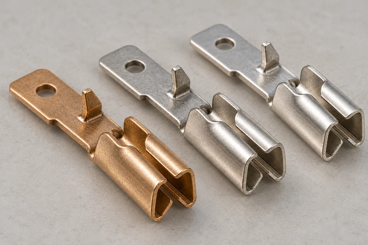
Receptacle contact materials must conduct well while keeping their ability to deflect and recover for a long time. Brass forms easily and is economical, but under sustained load at elevated temperature it relaxes relatively quickly. Phosphor bronze offers good spring properties and fatigue resistance and is widely used in receptacle contacts. Copper-nickel-silicon alloys or beryllium copper are considered when higher temperature or greater contact force is required.
Electrical conductivity also differs widely between alloys. Phosphor bronze has good spring properties but lower conductivity than brass, so the same cross-section generates more resistive heat. Copper-nickel-silicon alloys and some beryllium coppers conduct better than phosphor bronze and hold their force longer at temperature, at a higher material cost. For high-current contacts, heat in the bend and tail cross-sections must be evaluated together with beam contact force. Manufacturers’ stress-relaxation data come with temperature, time and initial-stress conditions and should be read against the actual operating conditions.
Plating helps control surface films and wear. Tin is economical and soft enough to deform during initial mating, but it needs adequate contact force and control of fretting. Prolonged operation at elevated temperature also requires assessment of changes among the tin layer, underplate and substrate. Silver is used in high-current connections, with tarnishing and wear conditions considered together. A nickel underplate can limit diffusion from the substrate, but suitability depends on the actual plating system and service conditions.
The plating of the mating plug blade matters too. Dissimilar platings in contact can wear and corrode differently, so changing only the receptacle contact may not deliver the expected improvement. Compare material and plating combinations after rated current, expected ambient temperature, mating frequency and target life have been defined.
MATERIAL & FINISH / Surface finish and formed geometry of copper-alloy contacts
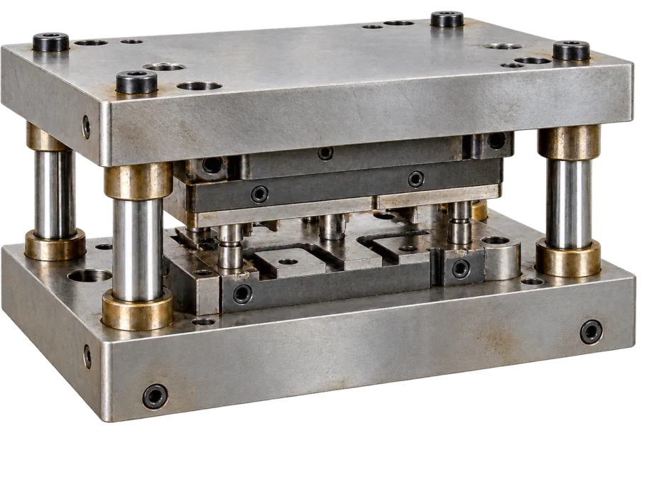
Most receptacle contacts are made by feeding coil stock one pitch at a time through a progressive die. Pilot holes register the strip and the outline is blanked. The beams and bend are then raised over several steps before the part is cut from the carrier. Forming in stages rather than in one large bend reduces cracking and springback and stabilises the final beam gap.
The beam gap is the dimension that sets interference and therefore contact force. Springback varies with strip thickness and hardness from lot to lot and with tool wear. The forming stations therefore include a means of gap adjustment, and the gap is measured at regular intervals during production. A bend line parallel to the rolling direction cracks more easily at the same radius. The bend radius-to-thickness ratio is kept within the formability range published by the strip manufacturer.
Burr orientation is chosen relative to the blade travel. A punched edge contains rollover, a burnished zone, a fracture zone and a burr, so being on the punch-entry side does not by itself make every mating surface smooth. Establish whether the blade bears on a broad sheet face or also encounters a cut edge. Orient the burr away from the sliding path and use edge finishing or coining where needed.
The timing of plating is part of the process design. Stamping pre-plated strip leaves base metal exposed on sheared edges; plating after forming covers the edges but changes thickness distribution and cost. Selective reel-to-reel plating can place the required deposit only on the contact area. Whatever the method, plating thickness is meaningful only when measured at the contact area.
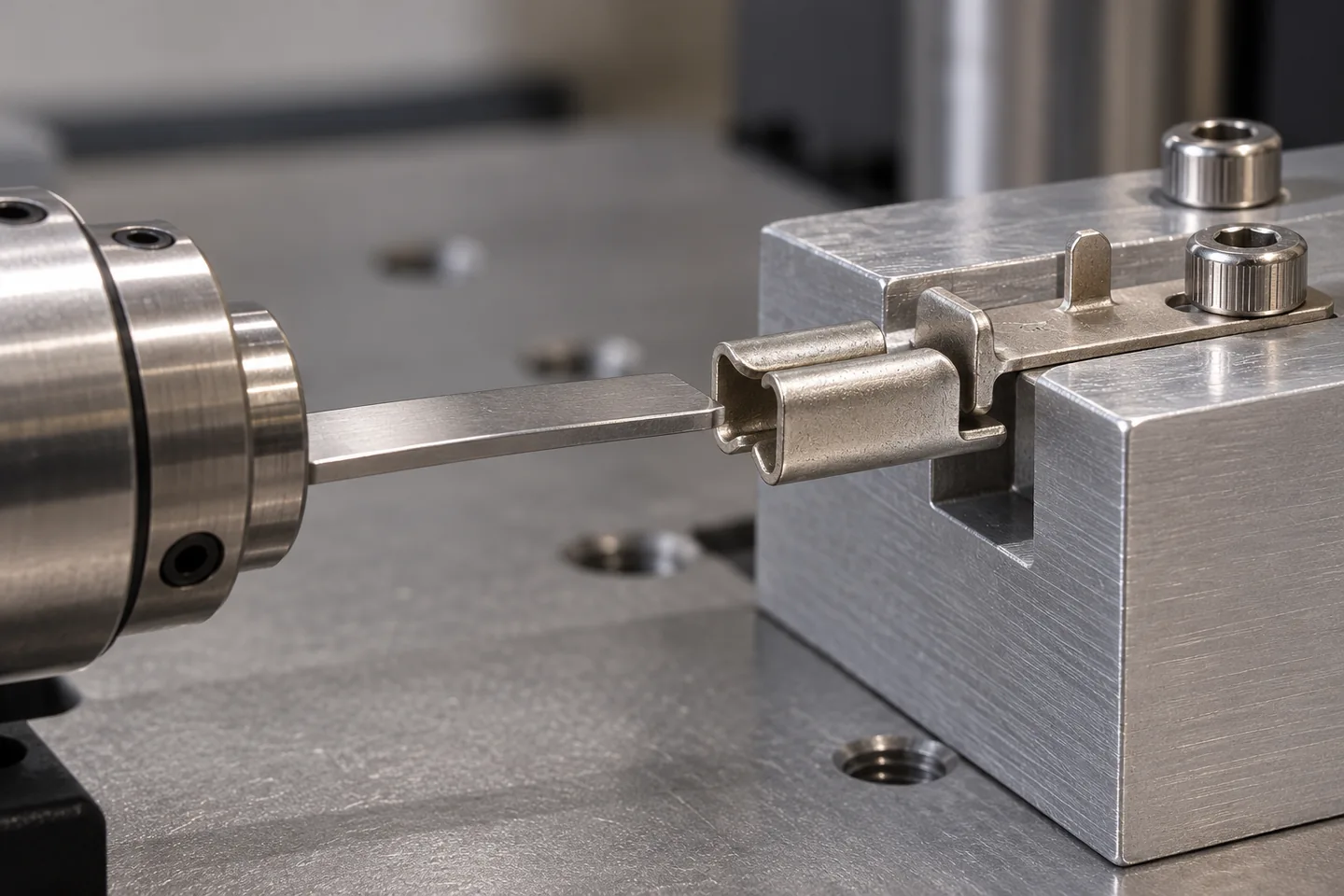
Approval begins with dimensional checks of beam gap, contact position and burr orientation, followed by insertion and withdrawal measurements with a specified blade or gauge. Distinguish a single-contact test from a test of the assembled outlet. Insertion and withdrawal forces reflect friction, lead-in geometry, plating and lubrication, and housing interference as well as normal force. They are therefore not direct measurements of normal force.
Low-level contact resistance testing limits open-circuit voltage as well as measuring current so that the test does not alter surface films. A four-wire arrangement separates current leads from voltage-sensing leads to reduce lead-resistance effects. Record the sensing locations to distinguish the mating interface from internal connections. Voltage drop under load and temperature-rise tests evaluate different operating conditions and should be assessed alongside the low-level measurement. Follow the applicable standard and component approval conditions, then check the actual PDU arrangement and simultaneous loading.
Long-term behaviour is checked by repeating the same measurements after heat ageing or temperature cycling. Comparing withdrawal force, resistance change and plating wear after repeated mating shows whether stress relaxation or wear becomes the limiting mechanism first. Plating thickness is measured at the contact area by X-ray fluorescence, and cross-sections can reveal bend cracking and the plating layers where needed.
| Test | What it shows | Record at approval |
|---|
| Beam gap and contact position | Interference and contact location | Measurement points, tolerances, values by lot |
|---|
| Insertion and withdrawal force | Retention and usability; axial force includes friction | Single contact or assembly, gauge, speed and cycles |
|---|
| Voltage drop and contact resistance | Resistance of mating and internal connections | Four-wire sensing locations, current and open-circuit voltage |
|---|
| Temperature rise under current | Heating under load | Test current and duration, ambient, thermocouple position |
|---|
| Re-test after ageing or cycling | Stress relaxation and wear | Test conditions and before/after comparison |
|---|
| Plating thickness and cross-section | Plating at contact area, bend condition | Locations, thickness, presence of cracks |
|---|
What it shows · Record at approval
- Beam gap and contact position
- Interference and contact location
- Measurement points, tolerances, values by lot
- Insertion and withdrawal force
- Retention and usability; axial force includes friction
- Single contact or assembly, gauge, speed and cycles
- Voltage drop and contact resistance
- Resistance of mating and internal connections
- Four-wire sensing locations, current and open-circuit voltage
- Temperature rise under current
- Heating under load
- Test current and duration, ambient, thermocouple position
- Re-test after ageing or cycling
- Stress relaxation and wear
- Test conditions and before/after comparison
- Plating thickness and cross-section
- Plating at contact area, bend condition
- Locations, thickness, presence of cracks
INSERTION TEST / Axial alignment of the reference blade and contact opening
Receptacle contact enquiries usually begin in one of four situations. An outlet in service runs hot or its plugs loosen, so the contact must be replaced. The existing supplier’s contact is no longer available. A new PDU design needs a contact that fits its housing, or a contact made in small quantities is to move to progressive-die production.
When only samples are available, the work starts with dimensions and beam gap. Composition, hardness, plating type and thickness then characterise the existing contact. A contact that has been in service may no longer show its original gap, so unused samples, the housing and the mating plug should be reviewed where possible. When the goal is to cure heating, examine load current, installation environment and internal connections together with the contact.
Feasibility, price and lead time cannot be confirmed before the drawings are reviewed. Housing space, blade dimensions, required withdrawal force and temperature-rise targets come first. Only then can material, thickness, plating and tooling be compared, and production conditions are set after prototype tests.
For a receptacle contact enquiry, please send contact samples or drawings and the housing and mating plug details. Add the rated current, operating temperature and required insertion and withdrawal forces. Symptoms such as heating or loosening, service time, expected quantity and target schedule make the review more specific. If only part of the information is available, send what you have and we will agree the measurements and tests needed.
Discuss receptacle contact manufacturing



 ID