


CHARGING CONNECTOR CONTACTS
급속충전 커넥터
핀·소켓 접점
급속충전 커넥터 접점의 구조·발열·내구성
Mate.
Conduct.
Monitor.
CHARGING CONNECTOR CONTACTS
정확한 결합.
안정적인 전달.
핀과 소켓의 형상·표면·종단을 연결하고, 접촉저항과 온도 감시로 충전 인터페이스를 검토합니다.
MATING · CONTACT · THERMAL · DURABILITY
Overview.
충전 손잡이 안의 작은 접촉부에서 고전류의 흐름을 살펴봅니다.
전기차 급속충전 커넥터 접점은 차량 인렛의 핀과 충전 플러그의 소켓이 만드는 고전류 인터페이스입니다. 눈에 잘 보이지 않는 접촉대, 도금과 케이블 종단이 충전 중의 열과 반복 사용의 내구성을 좌우합니다.
한 쌍의 핀과 소켓을 따라가며 결합 형상, 다점 접촉, 은도금, 저항 측정과 온도 감시를 연결합니다. 결합 구조와 열전달 경로를 3D로 살펴보고, 도면 검토부터 완성 어셈블리의 검증까지 필요한 기준을 정리합니다.
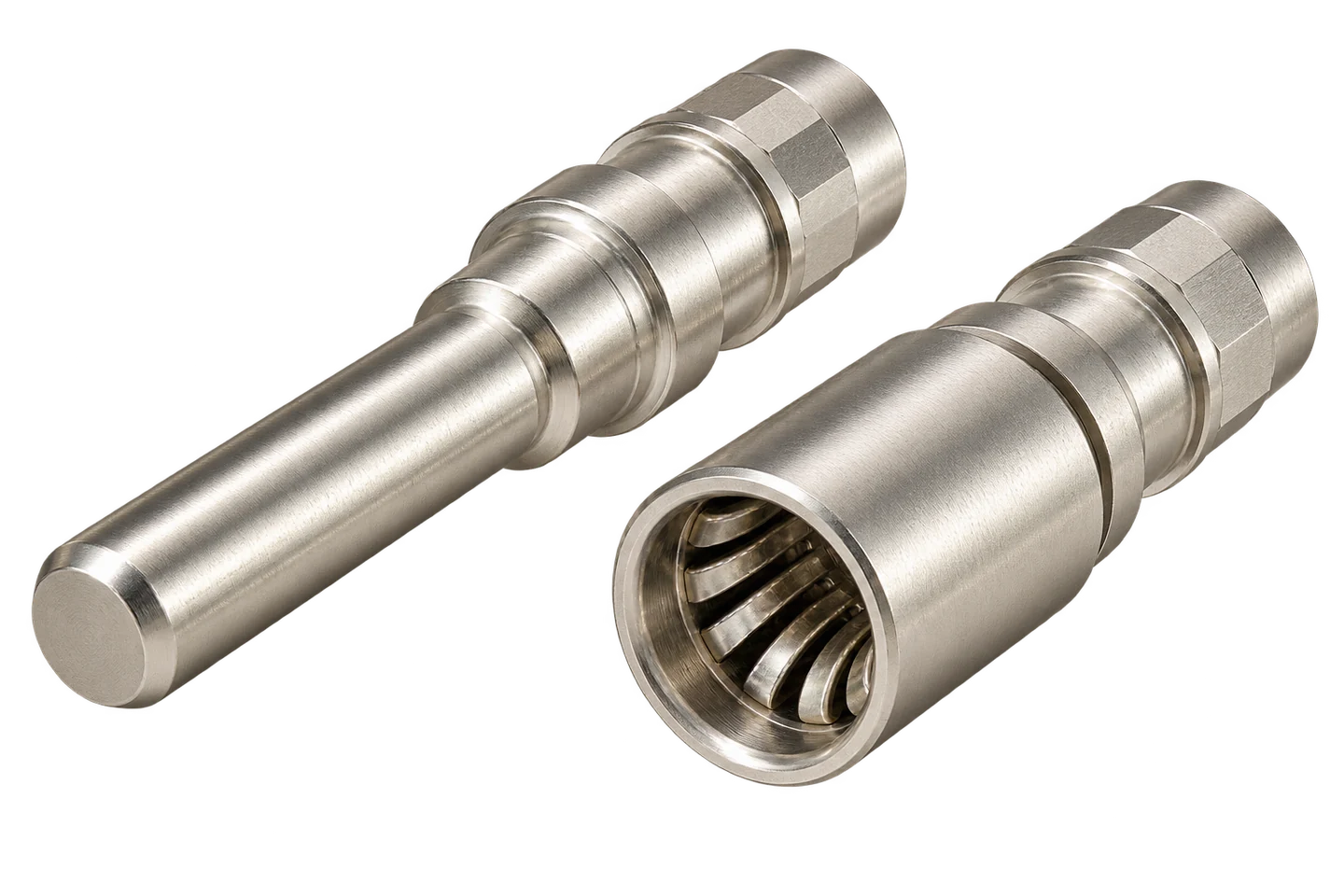
CONTACT COMPONENTS / 절연 지지체·소켓 몸체와 인렛 핀
INTERFACE & CURRENT PATH
충전 케이블에서 차량 인렛까지 부품의 역할을 따라갑니다.
01 / CHARGING INTERFACE
급속충전 전력은 핀과 소켓의 작은 접촉부를 통과합니다
충전 손잡이 안의 소켓과 차량 인렛의 핀이 만나 하나의 전류 경로를 만듭니다.
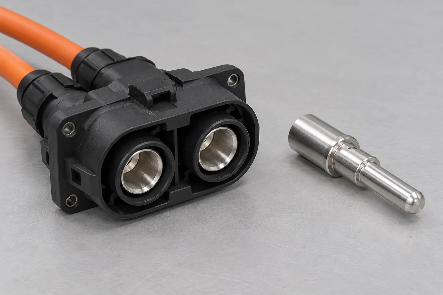
전기차 급속충전 커넥터 접점은 충전 케이블과 차량의 고전압 회로를 반복해서 연결하는 금속 인터페이스입니다. CCS 계열의 DC 전력 접점을 보면 차량 인렛 쪽의 수핀과 충전 플러그 쪽의 암소켓이 짝을 이룹니다. 사용자가 잡는 손잡이 안쪽에서는 이 작은 부품들이 충전 전류와 그에 따른 열을 감당합니다.
핀은 전류를 전달하는 연속된 도체이고, 소켓은 핀 외주를 탄성적으로 누르는 접촉 요소를 갖습니다. 절연 하우징은 두 극과 제어 접점을 분리하고 결합 방향을 안내합니다. 케이블 종단, 씰, 잠금장치, 온도센서는 각각 전류 연결, 환경 보호, 결합 유지와 열 감시를 담당합니다. 접점의 완성도는 이 주변 부품과 함께 평가해야 합니다.
이 글은 CCS 형태의 한 DC 전력 접점 쌍을 중심으로 구조를 설명합니다. 충전 규격과 제품에 따라 핀 배치, 절연 선단, 소켓 내부와 종단 방식은 달라집니다. 도면 검토에서는 인터페이스 규격과 상대 부품을 먼저 확정한 뒤 실제 결합 치수와 열관리 조건을 정해야 합니다. 외형이 비슷하다는 이유로 다른 제품의 접점을 교환해서는 안 됩니다.
차량 인렛 핀
차량 내부 도체로 이어지는 수접점
플러그 소켓
핀 외주를 누르는 탄성 암접점
주변 부품
절연·씰·잠금·온도 감시의 연결
급속충전 전력은 핀과 소켓의 작은 접촉부를 통과합니다 — 구조와 검토 항목
| 부품·조건 | 기능과 영향 | 확인할 사항 |
|---|---|---|
| 인렛 수핀 | 차량 쪽 전류 전달과 결합 기준 | 상대 소켓·접촉 랜드·고정 위치 |
| 플러그 암소켓 | 반복 결합과 탄성 접촉 | 내부 접촉대·삽입 깊이·지지 몸체 |
| 절연 하우징 | 극간 분리와 결합 방향 안내 | 키 형상·접촉 방지 구조·환경 경계 |
| 센서와 잠금 | 열 감시와 결합 상태 유지 | 감지 위치·상태 확인·제어 연동 |
인렛 수핀
기능과 영향
차량 쪽 전류 전달과 결합 기준
확인할 사항
상대 소켓·접촉 랜드·고정 위치
플러그 암소켓
기능과 영향
반복 결합과 탄성 접촉
확인할 사항
내부 접촉대·삽입 깊이·지지 몸체
절연 하우징
기능과 영향
극간 분리와 결합 방향 안내
확인할 사항
키 형상·접촉 방지 구조·환경 경계
센서와 잠금
기능과 영향
열 감시와 결합 상태 유지
확인할 사항
감지 위치·상태 확인·제어 연동
02 / CURRENT PATH
한 극의 저항과 두 극의 발열을 구분합니다
DC+와 DC−는 전류를 반씩 나누는 병렬 접점이 아닙니다.
정상적인 DC 충전에서 DC+와 DC−는 배터리로 이어지는 왕복 회로를 구성합니다. 따라서 각 극은 해당 충전 전류를 통과시키며, 한쪽의 열 상태가 양호하다고 다른 쪽도 같다고 볼 수 없습니다. 양극의 도체 길이와 케이블 배치, 접촉 상태, 주변 냉각 조건이 다르면 온도도 달라질 수 있습니다.
한 극의 경로를 케이블 도체, 종단부, 소켓 몸체, 탄성 접촉대, 핀, 차량 측 종단으로 나누면 손실의 위치를 찾기 쉬워집니다. 저항 측정값에는 전압 검출 위치 사이의 모든 구간이 포함됩니다. 접점 쌍만 측정한 값과 케이블 어셈블리 전체를 측정한 값을 같은 기준으로 비교하면 개선 대상이 어긋납니다.
전류 경로 옆에는 보호접지와 결합·제어를 위한 접점도 배치됩니다. 이들의 역할과 요구 치수는 DC 전력 접점과 다릅니다. 회로도, 단자 배치도와 단면도에서 전력 전달과 제어 기능을 구분하고, 센서 배선이나 접지 경로를 임의로 전력 경로에 포함하지 않아야 합니다.
양극 개별 평가
DC+와 DC−의 온도를 각각 확인
측정 구간 정의
접촉부와 전체 어셈블리를 구분
기능 분리
전력·접지·제어 접점의 역할 지정
DC+와 DC−는 전류를 반씩 나누는 병렬 접점이 아닙니다.
설계 확인
DC+와 DC−는 전류를 반씩 나누는 병렬 접점이 아닙니다.
한 극의 저항과 두 극의 발열을 구분합니다 — 구조와 검토 항목
| 부품·조건 | 기능과 영향 | 확인할 사항 |
|---|---|---|
| DC+·DC− | 각 극을 흐르는 충전 전류 | 극별 저항·온도·센서 위치 |
| 케이블 종단 | 도체와 접점 몸체의 연결 | 종단 전압 강하와 발열 위치 |
| 핀–소켓 계면 | 반복 결합으로 형성되는 접촉 | 측정 경계와 유효 결합 길이 |
| 보호접지·제어 | 보호와 충전 상태 전달 | 회로 기능과 접점 배열 일치 |
DC+·DC−
기능과 영향
각 극을 흐르는 충전 전류
확인할 사항
극별 저항·온도·센서 위치
케이블 종단
기능과 영향
도체와 접점 몸체의 연결
확인할 사항
종단 전압 강하와 발열 위치
핀–소켓 계면
기능과 영향
반복 결합으로 형성되는 접촉
확인할 사항
측정 경계와 유효 결합 길이
보호접지·제어
기능과 영향
보호와 충전 상태 전달
확인할 사항
회로 기능과 접점 배열 일치
GEOMETRY & ELASTIC CONTACT
조립되는 형상과 힘을 유지하는 구조를 함께 살펴봅니다.
03 / MATING GEOMETRY
핀 선단은 안내하고 원통 외주가 접촉합니다
진입 형상, 유효 접촉 길이와 하우징 정렬을 하나의 결합 조건으로 봅니다.
핀 선단의 라운드나 모따기는 소켓 입구로 부드럽게 진입하도록 돕습니다. 실제 접촉은 설계된 원통 외주와 소켓 내부 접촉 요소가 겹치는 구간에서 형성됩니다. 선단 형상과 접촉 랜드를 구분해야 하며, 제품에 포함된 절연 팁을 금속 접촉면으로 계산해서도 안 됩니다. 단면도에는 완전 결합 상태의 유효 겹침을 표시합니다.
핀 외경, 원통도와 표면 상태는 소켓의 탄성 변형량에 영향을 줍니다. 소켓 쪽에서는 접촉대의 자유 내경, 지지 위치와 허용 변위를 확인합니다. 도금 전 치수가 맞더라도 최종 표면처리 후 외경과 거칠기가 바뀌면 삽입력과 접촉압이 달라질 수 있습니다. 기능 검사는 최종 표면 상태의 부품으로 진행해야 합니다.
사용자는 충전 손잡이를 완벽히 일직선으로 움직이지 않습니다. 하우징 가이드가 초기 오정렬을 받아내고 접점은 승인된 범위에서 결합해야 합니다. 케이블의 무게와 측방향 당김이 접촉 요소에 계속 전달되면 한쪽 마모나 변형이 커질 수 있습니다. 핀 선단만 크게 둥글리는 방식으로 하우징과 지지 구조의 문제를 해결할 수는 없습니다.
진입부
핀 선단과 소켓 입구의 간섭 관리
접촉 랜드
완전 결합 후의 실제 겹침 길이
최종 치수
도금 이후의 외경·원통도·표면
설계 확인
진입 형상, 유효 접촉 길이와 하우징 정렬을 하나의 결합 조건으로 봅니다.
핀 선단은 안내하고 원통 외주가 접촉합니다 — 구조와 검토 항목
| 부품·조건 | 기능과 영향 | 확인할 사항 |
|---|---|---|
| 선단·입구 | 초기 진입과 걸림 | 라운드·모따기·절연 팁의 구분 |
| 접촉 길이 | 유효 접촉대의 위치 | 허용 공차에서 완전 결합 상태 확인 |
| 외경·내경 | 소켓 탄성 변형량 | 최종 도금 상태로 치수와 삽입력 확인 |
| 가이드·지지 | 편심과 케이블 반력 전달 | 최악 조립 조건에서 측하중 검토 |
선단·입구
기능과 영향
초기 진입과 걸림
확인할 사항
라운드·모따기·절연 팁의 구분
접촉 길이
기능과 영향
유효 접촉대의 위치
확인할 사항
허용 공차에서 완전 결합 상태 확인
외경·내경
기능과 영향
소켓 탄성 변형량
확인할 사항
최종 도금 상태로 치수와 삽입력 확인
가이드·지지
기능과 영향
편심과 케이블 반력 전달
확인할 사항
최악 조립 조건에서 측하중 검토
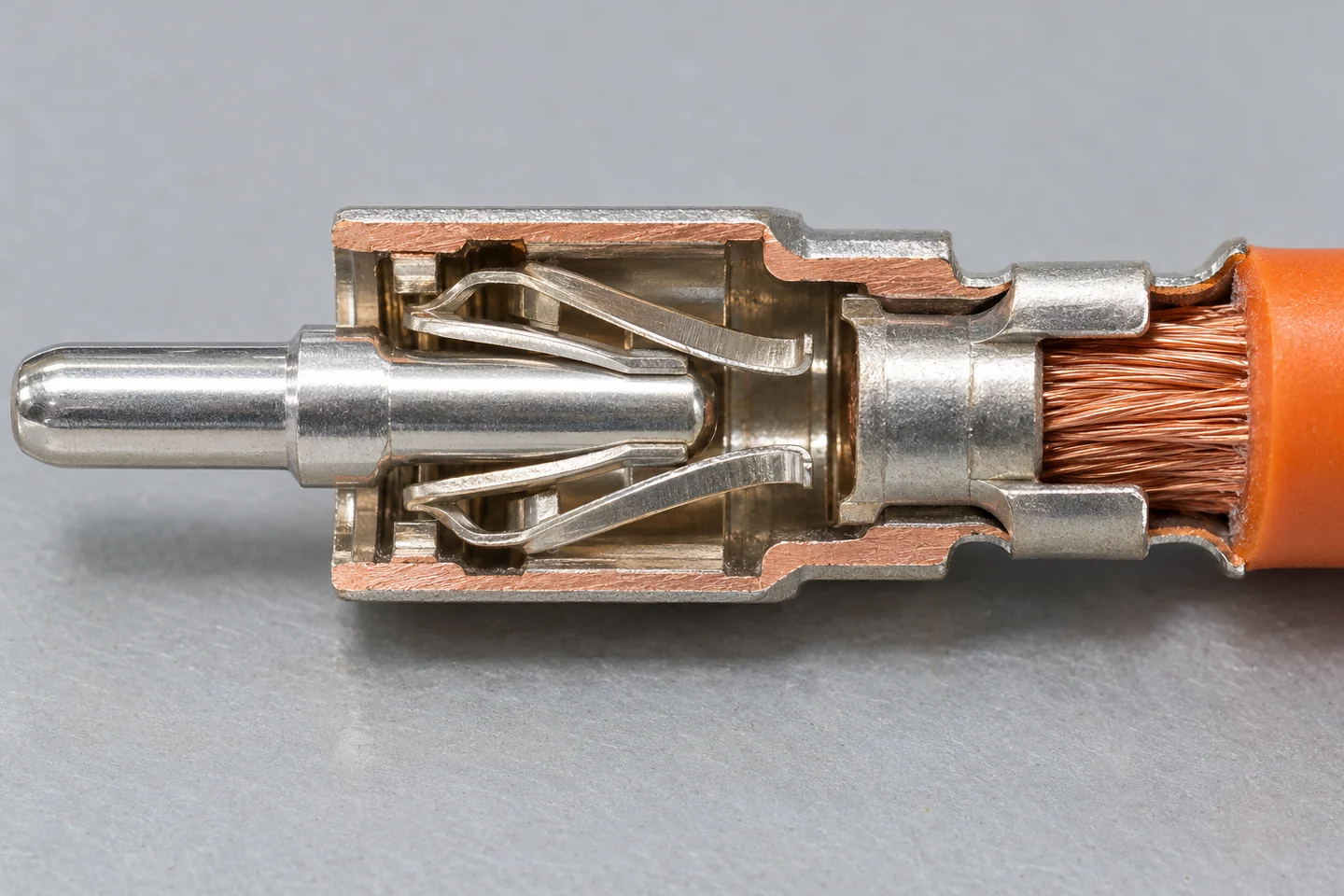
MATING INTERFACE / 핀 외주와 소켓 내부의 유효 접촉 구간
04 / MULTIPOINT CONTACT
여러 접촉점이 안정적으로 눌려야 전류가 분산됩니다
접촉점 개수만 늘리는 것으로 낮은 저항과 내구성이 보장되지는 않습니다.
고전류 소켓에는 절개된 탄성 핑거, 별도 라멜라 접촉대나 다른 다점 접촉 구조가 사용됩니다. 이 글의 단면은 지지 몸체 안에 탄성 접촉대를 배치한 구성을 다룹니다. 핀이 들어오면 접촉 요소가 변형되면서 여러 위치에서 압력을 만들고, 그 접촉점들을 통해 핀과 소켓 사이로 전류가 이동합니다.
다점 접촉은 여러 전류 경로를 제공하지만 각 경로의 전류가 정확히 같지는 않습니다. 형상 공차, 압력, 표면막과 접촉대 지지 상태에 따라 분담이 달라집니다. 일부 요소만 과하게 눌리거나 접촉이 빠지면 전류가 특정 위치에 집중할 수 있습니다. 접촉점 수로 단일 접점 저항을 단순히 나눈 값은 실제 제품의 검증값이 아닙니다.
탄성 요소에는 전도성과 함께 반복 변형, 높은 온도에서의 응력 완화와 지지 구조의 안정성이 요구됩니다. 지나치게 큰 압력은 삽입력을 높이고 마모를 빠르게 할 수 있으며, 부족한 압력은 접촉 상태를 불안정하게 만듭니다. 목표는 처음의 강한 압력이 아니라 사용 조건을 거친 뒤에도 유지되는 적절한 압력 분포입니다.
접촉점 개수만 늘리는 것으로 낮은 저항과 내구성이 보장되지는 않습니다.
여러 접촉점이 안정적으로 눌려야 전류가 분산됩니다 — 구조와 검토 항목
| 부품·조건 | 기능과 영향 | 확인할 사항 |
|---|---|---|
| 탄성 요소 | 핀을 누르는 복수 접촉점 | 치수·재료 상태·허용 변위 |
| 몸체 연결 | 접촉대에서 소켓으로 전류 전달 | 지지 홈·고정·전기적 연속성 |
| 압력 분포 | 전류 집중과 국부 마모 | 편심·공차 한계에서 접촉 유지 |
| 삽입·이탈력 | 사용성 및 기계적 부하 | 초기와 내구 후 힘–변위 곡선 |
탄성 요소
기능과 영향
핀을 누르는 복수 접촉점
확인할 사항
치수·재료 상태·허용 변위
몸체 연결
기능과 영향
접촉대에서 소켓으로 전류 전달
확인할 사항
지지 홈·고정·전기적 연속성
압력 분포
기능과 영향
전류 집중과 국부 마모
확인할 사항
편심·공차 한계에서 접촉 유지
삽입·이탈력
기능과 영향
사용성 및 기계적 부하
확인할 사항
초기와 내구 후 힘–변위 곡선
3D · 차량 핀과 충전 소켓의 다점 접촉
PIN · SOCKET · CONTACT BANDID SOLUTECH / 01
접촉부 단면
인터랙티브 3D를 준비하고 있습니다.
부분단면에서 소켓 몸체와 스프링 밴드를 구분합니다. 탄성편이 핀을 누르는 접촉 구간과 절연 지지의 위치를 확인합니다.
드래그·방향키: 회전 / + −: 확대·축소 / Home: 초기화차량 핀과 충전 소켓의 다점 접촉
접촉 면적은 보이는 금속 표면 전체와 같지 않습니다.
MATERIAL & TERMINATION
접촉 표면에서 케이블 종단까지 전기적 연속성을 이어갑니다.
05 / CONDUCTOR AND FINISH
구리계 도체와 은도금은 역할을 나누어 설계합니다
몸체의 전도성, 탄성부의 강도와 표면의 마찰·마모를 함께 맞춥니다.
전력 접점 몸체는 전류와 열을 전달해야 하고, 탄성 접촉 요소는 변형 후에도 압력을 유지해야 합니다. 두 역할이 한 재료 안에 통합될 수도 있고 서로 다른 재료와 부품으로 나뉠 수도 있습니다. 구리라는 재질명만으로 설계를 확정하지 않고 합금 번호, 조질, 도전율과 실제 온도에서의 기계적 특성을 확인합니다.
은계 표면은 고전류 결합면에서 널리 사용되지만 은도금이라는 한 항목만으로 내구성이 정해지지는 않습니다. 최종 두께 분포, 경도, 거칠기, 하부층과의 적합성, 상대 접촉면이 함께 작용합니다. 복합 은도금이나 윤활계도 존재하므로 순은·경질 은·복합층의 시험 결과를 서로 같은 조건처럼 옮겨 쓰지 않습니다.
도면에는 실제 접촉 랜드의 도금 범위와 두께 측정 위치를 명시합니다. 소켓 안쪽의 그늘진 위치, 선단과 모서리는 외부 평면과 도금 분포가 다를 수 있습니다. 표면 변색만으로 전기적 불량을 확정하거나, 반대로 광택만으로 양호하다고 판정하지 않습니다. 내구 후 마모 상태와 저항 변화를 연결해서 표면 사양을 승인합니다.
도체 몸체
전기·열 전달을 위한 재료와 단면
탄성 재료
반복 변형과 온도에서의 힘 유지
접촉 표면
두께·경도·마찰·상대재의 조합
설계 확인
몸체의 전도성, 탄성부의 강도와 표면의 마찰·마모를 함께 맞춥니다.
구리계 도체와 은도금은 역할을 나누어 설계합니다 — 구조와 검토 항목
| 부품·조건 | 기능과 영향 | 확인할 사항 |
|---|---|---|
| 합금·조질 | 전도성과 기계적 특성 | 재료 식별과 공급 상태 |
| 도금 범위 | 유효 접촉면의 보호 | 접촉 랜드와 측정 위치 지정 |
| 두께·거칠기 | 최종 치수와 마모 거동 | 국부 분포 및 상대면과의 조합 |
| 하부층·윤활 | 계면 안정성과 마찰 변화 | 사용 환경·세정·씰 적합성 |
합금·조질
기능과 영향
전도성과 기계적 특성
확인할 사항
재료 식별과 공급 상태
도금 범위
기능과 영향
유효 접촉면의 보호
확인할 사항
접촉 랜드와 측정 위치 지정
두께·거칠기
기능과 영향
최종 치수와 마모 거동
확인할 사항
국부 분포 및 상대면과의 조합
하부층·윤활
기능과 영향
계면 안정성과 마찰 변화
확인할 사항
사용 환경·세정·씰 적합성
06 / CABLE TERMINATION
핀과 소켓 뒤의 케이블 종단도 같은 전류를 받습니다
접촉 계면의 개선과 종단·지지·냉각 설계를 함께 진행합니다.
핀과 소켓이 잘 맞아도 뒤쪽 케이블 종단에서 손실이 커지면 어셈블리 온도는 올라갑니다. 압착 종단은 전선 단면적만 같다고 같은 조건을 적용할 수 없습니다. 소선 구성, 도체 표면, 피복 제거 길이, 배럴과 금형의 조합을 맞추고, 손상된 소선이나 피복 혼입이 없는지 확인합니다. 굵은 케이블에서는 종단 방향과 압착 중 길이 변화도 조립성에 영향을 줍니다.
압착 형상과 인장 성능은 필요한 검사항목이지만 전기적 안정성을 각각 대신하지는 못합니다. 단면에서 소선 분포와 배럴 결함을 살펴보고, 지정 구간의 전압 강하와 온도 상승을 확인합니다. 용접식 종단을 사용하는 설계라면 접합 면적, 잔류 변형과 열영향을 별도로 승인해야 하며, 압착 기준을 그대로 적용하지 않습니다.
케이블 인출부의 지지와 씰은 종단이 굽힘과 당김을 직접 받지 않도록 설계합니다. 수랭 구조에서는 냉각수가 접점 가까이 열을 빼내는 경로와 전기 절연 경계가 함께 필요합니다. 직접 냉각과 간접 냉각의 구조는 다르므로 유체 적합성, 누설, 압력 손실과 센서 배치를 실제 어셈블리 단위로 검토합니다.
종단 품질
단면·전압 강하·온도 상승의 연결
하중 분리
케이블 반력을 받는 지지 구조
냉각 경로
열 전달과 절연 경계를 함께 설계
설계 확인
접촉 계면의 개선과 종단·지지·냉각 설계를 함께 진행합니다.
핀과 소켓 뒤의 케이블 종단도 같은 전류를 받습니다 — 구조와 검토 항목
| 부품·조건 | 기능과 영향 | 확인할 사항 |
|---|---|---|
| 전선·배럴·금형 | 압착 조건과 도체 연결 | 승인 조합과 공급 이력 |
| 단면·전기 검사 | 결함과 손실의 서로 다른 측면 | 소선·균열·전압 강하·발열 |
| 인출부·씰 | 굽힘·당김과 환경 침투 | 지지 간격·배선 방향·씰 상태 |
| 수랭 회로 | 열 제거와 유체 경계 | 유량·유체·누설·절연 적합성 |
전선·배럴·금형
기능과 영향
압착 조건과 도체 연결
확인할 사항
승인 조합과 공급 이력
단면·전기 검사
기능과 영향
결함과 손실의 서로 다른 측면
확인할 사항
소선·균열·전압 강하·발열
인출부·씰
기능과 영향
굽힘·당김과 환경 침투
확인할 사항
지지 간격·배선 방향·씰 상태
수랭 회로
기능과 영향
열 제거와 유체 경계
확인할 사항
유량·유체·누설·절연 적합성
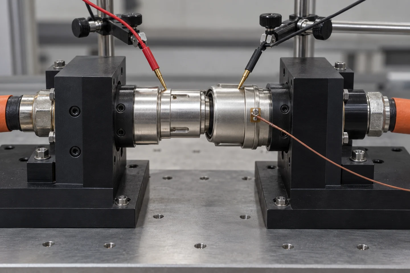
CONTACT VERIFICATION / 조립 접점의 저항·온도 평가 구성
RESISTANCE & THERMAL PATH
전기적 손실이 발생하는 위치와 열이 빠져나가는 경로를 구분합니다.
07 / RESISTANCE MEASUREMENT
충전 커넥터 접점의 저항은 측정 위치와 함께 기록합니다
마이크로옴 단위의 비교에서는 전압 검출 위치와 온도 차이가 결론을 바꿀 수 있습니다.
충전 커넥터 접점의 저항을 비교하려면 먼저 측정 경계를 고정합니다. 소켓과 핀 사이만 볼 것인지, 종단부까지 포함할 것인지 정하고 전압 검출 위치를 도면에 남깁니다. 4선식 측정은 전류 공급선과 전압 검출선을 분리해 리드선 전압 강하의 영향을 줄입니다. 그러나 검출점 사이에 포함된 몸체와 종단의 저항까지 자동으로 제거해 주지는 않습니다.
시험 전류, 전류 인가 시간, 주변 온도와 측정 시점도 결과에 영향을 줍니다. 큰 전류는 자체 발열로 도체 저항을 바꿀 수 있고, 미세한 열기전력은 낮은 저항의 전압 신호에 겹칠 수 있습니다. 필요한 경우 전류 반전이나 오프셋 보정으로 이를 줄이고, 장비 분해능뿐 아니라 치구의 반복 설치 오차와 측정 불확도를 확인합니다.
신품, 반복 결합 후, 환경 노출 후의 데이터를 같은 조건으로 비교해야 변화가 드러납니다. 시료를 다시 뺐다 꽂는 행위 자체가 접촉 위치와 표면막을 바꿀 수 있으므로 재결합 횟수도 기록합니다. 낮은 전류에서의 계면 상태 평가와 실제 충전 전류에서의 온도 상승 시험은 목적이 다르며, 두 시험의 결과를 함께 해석합니다.
4선식 측정
전류선과 전압 검출선 분리
온도와 시간
자체 발열과 열기전력 관리
상태 이력
재결합·내구·환경 노출 기록
마이크로옴 단위의 비교에서는 전압 검출 위치와 온도 차이가 결론을 바꿀 수 있습니다.
설계 확인
마이크로옴 단위의 비교에서는 전압 검출 위치와 온도 차이가 결론을 바꿀 수 있습니다.
충전 커넥터 접점의 저항은 측정 위치와 함께 기록합니다 — 구조와 검토 항목
| 부품·조건 | 기능과 영향 | 확인할 사항 |
|---|---|---|
| 전압 검출점 | 포함되는 저항 구간 | 위치·접촉 방법·극성 고정 |
| 시험 전류·시간 | 표면 상태와 자체 발열 | 시험 목적에 맞는 조건 지정 |
| 온도·열기전력 | 저항과 미소 전압의 변화 | 온도 기록·안정화·오프셋 검토 |
| 시료 이력 | 재결합으로 계면 상태 변화 | 초기 상태와 노출 순서 연결 |
전압 검출점
기능과 영향
포함되는 저항 구간
확인할 사항
위치·접촉 방법·극성 고정
시험 전류·시간
기능과 영향
표면 상태와 자체 발열
확인할 사항
시험 목적에 맞는 조건 지정
온도·열기전력
기능과 영향
저항과 미소 전압의 변화
확인할 사항
온도 기록·안정화·오프셋 검토
시료 이력
기능과 영향
재결합으로 계면 상태 변화
확인할 사항
초기 상태와 노출 순서 연결
3D · 소켓·크림프·케이블의 열경로와 온도 감시
TERMINATION & THERMAL PATHID SOLUTECH / 02
열전달 경로
인터랙티브 3D를 준비하고 있습니다.
접촉부의 열은 금속 종단부와 케이블, 주변 구조로 전달됩니다. 화살표는 전달 경로를 표시하며 온도 분포나 냉각 성능을 수치화하지 않습니다.
드래그·방향키: 회전 / + −: 확대·축소 / Home: 초기화소켓·크림프·케이블의 열경로와 온도 감시
08 / JOULE HEAT AND COOLING
전류가 커질수록 접촉저항의 작은 차이가 중요해집니다
발열은 전류의 제곱으로 증가하며, 실제 온도는 열이 빠져나가는 조건에도 좌우됩니다.
정해진 구간의 전기 손실은 전류의 제곱과 그 구간의 저항으로 계산합니다. 예를 들어 한 극의 측정 저항을 0.10 mΩ으로 가정하면 300 A에서 9 W, 400 A에서 16 W의 손실이 생깁니다. 이 값은 저항을 일정하게 놓은 계산 예이며 제품의 허용 전류나 시험 결과가 아닙니다. 실제 저항은 온도와 접촉 상태가 바뀌면 달라집니다.
발생한 열은 핀·소켓 몸체, 케이블, 하우징과 냉각 경로로 분산됩니다. 동일한 접촉저항이라도 케이블 길이와 단면, 주변 온도, 설치 공간, 냉각수 입구 온도와 유량에 따라 접점 온도가 달라집니다. 접점 가까이의 열을 직접 줄이는 개선과 멀리서 열을 배출하는 개선을 구분해야 설계 변경의 효과를 설명할 수 있습니다.
아래 온도 관계는 고정된 경계 조건에서 한 개의 대표 열원으로 단순화한 정상상태 근사입니다. 실제 충전은 전류가 시간에 따라 바뀌며, 두 극과 케이블의 열이 서로 영향을 줍니다. 따라서 상세 설계에서는 과도 응답, 온도에 따른 저항 변화와 냉각 저하 상태까지 해석하고 실제 어셈블리의 온도 측정으로 비교해야 합니다.
P_loss = I²R · ΔT ≈ P_loss Rθ
P_loss: 정해진 구간의 전기 손실 [W] · I: 그 구간을 흐르는 DC 전류 [A] · R: 해당 상태에서의 전기저항 [Ω] · ΔT: 대표 열원과 정해진 열적 경계 사이의 온도차 [K] · Rθ: 그 경로의 유효 열저항 [K/W]. ΔT 식은 단일 열원·고정 경계·정상상태 근사이며 다중 열원, 과도 응답과 온도 의존 저항은 별도로 다룹니다.
설계 확인
발열은 전류의 제곱으로 증가하며, 실제 온도는 열이 빠져나가는 조건에도 좌우됩니다.
전류가 커질수록 접촉저항의 작은 차이가 중요해집니다 — 구조와 검토 항목
| 부품·조건 | 기능과 영향 | 확인할 사항 |
|---|---|---|
| 전류와 저항 | 국부 발열량 결정 | 같은 측정 구간과 온도 기준 적용 |
| 대표 열저항 | 열원과 경계 사이의 온도차 | 설치·냉각 조건을 고정해 산정 |
| 냉각 유량·온도 | 열 전달과 압력 손실 변화 | 입구 온도·유량·이상 상태 검토 |
| 충전 시간 이력 | 정상상태 도달 전의 최고 온도 | 전류 프로파일과 열용량 반영 |
전류와 저항
기능과 영향
국부 발열량 결정
확인할 사항
같은 측정 구간과 온도 기준 적용
대표 열저항
기능과 영향
열원과 경계 사이의 온도차
확인할 사항
설치·냉각 조건을 고정해 산정
냉각 유량·온도
기능과 영향
열 전달과 압력 손실 변화
확인할 사항
입구 온도·유량·이상 상태 검토
충전 시간 이력
기능과 영향
정상상태 도달 전의 최고 온도
확인할 사항
전류 프로파일과 열용량 반영
같은 저항이라도 냉각 조건이 다르면 온도는 달라집니다.
MONITORING & SERVICE LIFE
충전 중의 열 상태와 반복 사용 후의 계면을 연결합니다.
09 / THERMAL MONITORING
센서는 가장 뜨거운 접촉점과 같은 온도를 즉시 읽지 않습니다
감지 위치와 열 전달 지연을 고려해야 전류 제한이 제때 작동합니다.
접촉면의 열은 금속 몸체와 열전달 재료를 거쳐 센서에 도달합니다. 센서가 접점에서 멀거나 접촉 상태가 불안정하면 실제 국부 온도와 측정값 사이에 차이가 생깁니다. DC+와 DC−의 열 상태가 서로 다를 수 있으므로 각각의 감지 경로를 평가해야 합니다. 하우징 표면을 한 번 측정한 값만으로 내부 최고 온도를 판단하지 않습니다.
센서 주변의 열전달 재료는 열을 잘 전달하면서 요구되는 전기 절연을 유지해야 합니다. 재료의 열전도율뿐 아니라 두께, 압축 상태, 기포와 계면 열저항이 응답에 영향을 줍니다. 여기서 말하는 열저항은 핀–소켓 전기 접촉저항과 다른 물리량입니다. 조립 후 센서 고정과 절연 경계를 함께 검사해야 측정 성능을 재현할 수 있습니다.
온도 감시는 충전 전류 제한과 정지 동작에 연결되어야 합니다. 제어기는 센서 오차와 응답 지연, 주변 온도와 냉각 상태를 고려하고, 단선·단락 등 센서 이상을 구분해 처리해야 합니다. 정격 수치 하나를 입력하는 방식보다 정상 냉각, 높은 주변 온도, 열화 접점과 냉각 저하에서 감시와 제어가 어떻게 반응하는지 확인하는 것이 중요합니다.
감지 위치와 열 전달 지연을 고려해야 전류 제한이 제때 작동합니다.
설계 확인
감지 위치와 열 전달 지연을 고려해야 전류 제한이 제때 작동합니다.
센서는 가장 뜨거운 접촉점과 같은 온도를 즉시 읽지 않습니다 — 구조와 검토 항목
| 부품·조건 | 기능과 영향 | 확인할 사항 |
|---|---|---|
| 센서 위치 | 국부 최고 온도와의 차이 | 극별 거리·열 경로·조립 편차 |
| 열전달 재료 | 응답 속도와 절연 성능 | 두께·기포·압축·절연 적합성 |
| 응답 시간 | 급격한 발열의 감지 지연 | 시간 이력과 보호 여유 검토 |
| 고장 감시 | 비정상 신호와 냉각 저하 | 단선·단락·센서 이탈 대응 확인 |
센서 위치
기능과 영향
국부 최고 온도와의 차이
확인할 사항
극별 거리·열 경로·조립 편차
열전달 재료
기능과 영향
응답 속도와 절연 성능
확인할 사항
두께·기포·압축·절연 적합성
응답 시간
기능과 영향
급격한 발열의 감지 지연
확인할 사항
시간 이력과 보호 여유 검토
고장 감시
기능과 영향
비정상 신호와 냉각 저하
확인할 사항
단선·단락·센서 이탈 대응 확인
10 / REPEATED MATING AND ENVIRONMENT
반복 결합은 접촉 흔적과 표면 상태를 바꿉니다
삽입 횟수와 함께 하중 방향, 오염과 보관 조건을 평가합니다.
충전할 때마다 핀 외주와 소켓 접촉 요소 사이에 미끄럼이 생깁니다. 이 이동은 표면막의 일부를 바꾸는 동시에 도금 마모와 마찰 입자를 만들 수 있습니다. 결합을 반복할수록 접촉 흔적이 어디에 집중되는지, 삽입력과 저항이 어떻게 변하는지 함께 봐야 합니다. 정해진 횟수를 왕복했다는 사실만으로 사용 수명이 설명되지는 않습니다.
야외 충전에서는 먼지, 수분과 염분, 온도 변화가 결합면 주변에 작용합니다. 케이블의 무게와 당김은 접촉 하중을 비대칭으로 만들 수 있고, 보관 홀더의 방향은 오염 노출에 영향을 줍니다. 노출 순서에 따라 결과가 달라질 수 있으므로 반복 결합 후 환경 시험인지, 환경 노출 뒤 결합 시험인지 시험 계획에 명시합니다.
유지관리 방법도 접촉 시스템의 일부입니다. 표면을 임의로 연마하거나 승인되지 않은 세정제와 윤활제를 쓰면 도금, 절연체와 씰이 달라질 수 있습니다. 교체 가능한 접점이라면 교체 부품과 작업 절차, 조립 후 검사 범위를 제품별로 정합니다. 저항·온도·외관의 변화와 손상 위치를 함께 보아 정상 마모와 이상 상태를 구분합니다.
마모 흔적
도금 상태와 접촉 위치의 변화
복합 환경
먼지·수분·온도·측하중의 순서
유지관리
승인된 세정·교체·재검사 절차
설계 확인
삽입 횟수와 함께 하중 방향, 오염과 보관 조건을 평가합니다.
반복 결합은 접촉 흔적과 표면 상태를 바꿉니다 — 구조와 검토 항목
| 부품·조건 | 기능과 영향 | 확인할 사항 |
|---|---|---|
| 반복 결합 | 마찰과 도금 마모 | 힘·저항·마모 위치의 추세 |
| 환경 노출 | 표면막과 절연 상태 변화 | 시험 조건·순서·보관 상태 |
| 측방향 하중 | 편마모와 접촉 압력 변화 | 케이블 방향과 지지 조건 |
| 세정·교체 | 표면과 밀봉 상태 재형성 | 허용 재료·절차·최종 검사 |
반복 결합
기능과 영향
마찰과 도금 마모
확인할 사항
힘·저항·마모 위치의 추세
환경 노출
기능과 영향
표면막과 절연 상태 변화
확인할 사항
시험 조건·순서·보관 상태
측방향 하중
기능과 영향
편마모와 접촉 압력 변화
확인할 사항
케이블 방향과 지지 조건
세정·교체
기능과 영향
표면과 밀봉 상태 재형성
확인할 사항
허용 재료·절차·최종 검사
VALIDATION & PRODUCTION
부품의 기능을 충전 시스템의 승인과 양산 관리로 연결합니다.
11 / LOCKING AND ELECTRICAL SEQUENCE
핀과 소켓의 분리는 전류 차단이 완료된 뒤에 이뤄집니다
결합 감지, 잠금, 통신과 전력 개폐가 하나의 충전 절차로 이어져야 합니다.
충전 커넥터의 핀–소켓은 정상적인 충전 전류를 기계적으로 끊기 위한 스위치가 아닙니다. 충전 시작 전에는 결합 상태와 잠금, 필요한 통신과 보호 조건을 확인합니다. DC 시스템은 적용 절차에 따른 절연 확인과 전압 정합 등의 준비를 거쳐 전력 전달을 시작합니다. 접점이 닿았다는 사실만으로 즉시 충전 전류를 흘리는 구조로 이해하면 안 됩니다.
정상 종료에서는 시스템이 충전 전류를 줄여 전력 전달을 중지하고, 개폐장치와 잔류전압 등 필요한 안전 상태를 확인한 뒤 잠금 해제와 분리를 허용합니다. 구체적인 순서와 판정 조건은 적용 규격과 차량·충전기의 구현에 따라 정해집니다. 잠금 핀을 빼는 동작과 전류 차단은 다른 기능이며, 인터록과 제어는 둘 사이의 순서를 보장해야 합니다.
절연 거리, 접촉 방지와 밀봉 구조도 금속 접점의 치수만으로 확보되지 않습니다. 최종 하우징 재료, 오염 조건과 조립 상태에서 검토해야 합니다. 신호 손실, 센서 이상, 냉각 저하나 잠금 불완전 같은 상태에서는 정상 충전 흐름을 그대로 유지하지 않도록 설계합니다. 개발 시험은 개별 접점과 완성 충전 인터페이스의 검증 범위를 구분해 진행합니다.
시작 조건
결합·잠금·통신·보호 상태 확인
종료 순서
전력 전달 중지 후 안전한 분리
시스템 검증
정상·고장 상태의 인터록 평가
결합 감지, 잠금, 통신과 전력 개폐가 하나의 충전 절차로 이어져야 합니다.
설계 확인
결합 감지, 잠금, 통신과 전력 개폐가 하나의 충전 절차로 이어져야 합니다.
핀과 소켓의 분리는 전류 차단이 완료된 뒤에 이뤄집니다 — 구조와 검토 항목
| 부품·조건 | 기능과 영향 | 확인할 사항 |
|---|---|---|
| 결합·잠금 | 전력 전달 중 물리적 이탈 방지 | 상태 검출과 기계적 유지 |
| 전력 제어 | 시작·정지와 개폐 순서 | 통신·보호·전압 조건의 연동 |
| 절연·접촉 방지 | 활선부와 외부 사이의 경계 | 재료·거리·오염·조립 상태 |
| 고장 대응 | 비정상 상태에서 충전 제한 | 센서·신호·냉각·잠금 오류 시험 |
결합·잠금
기능과 영향
전력 전달 중 물리적 이탈 방지
확인할 사항
상태 검출과 기계적 유지
전력 제어
기능과 영향
시작·정지와 개폐 순서
확인할 사항
통신·보호·전압 조건의 연동
절연·접촉 방지
기능과 영향
활선부와 외부 사이의 경계
확인할 사항
재료·거리·오염·조립 상태
고장 대응
기능과 영향
비정상 상태에서 충전 제한
확인할 사항
센서·신호·냉각·잠금 오류 시험
12 / QUALIFICATION AND RELEASE
충전 커넥터 접점의 도면과 운전 조건을 함께 승인합니다
초기 측정값부터 내구 후 상태까지 같은 제품 조합으로 관리합니다.
개발 입력에는 핀과 소켓의 도면, 최종 도금 사양, 상대 부품과 하우징, 케이블 구조, 전류 프로파일과 주변 온도를 포함합니다. 수랭식이라면 냉각수와 유량 범위, 센서 구조도 필요합니다. 전류 정격은 이런 조건과 함께 검증된 값이므로 다른 공급사의 숫자나 단품의 도전율만으로 완성품 정격을 정할 수 없습니다.
검증 계획은 치수와 결합력, 구간별 저항, 온도 상승, 기계적 내구와 환경 노출, 절연·보호 기능을 연결합니다. 적용하는 IEC 62196 계열의 커플러 요구, IEC 61851 계열의 충전 시스템 요구와 관련 통신 규격은 대상과 판본을 구분해 확정합니다. 완성품과 개별 접점의 시험 범위도 구별하며, 규격명을 문서에 적는 것과 적합성을 확인하는 것은 다른 단계입니다.
양산에서는 재료와 도금 로트, 가공 치수, 접촉대 조립, 종단 공정과 최종 검사 결과를 추적합니다. 동일한 형상의 부품이라도 합금·도금계·접촉대·케이블·센서가 바뀌면 기존 승인 범위를 다시 검토합니다. 개발 문의에는 요구 전류의 시간 이력, 상대 부품 정보와 검사 기준을 함께 제공하면 제품의 구조와 제조 조건을 구체적으로 협의할 수 있습니다.
개발 입력
상대 부품·전류 이력·냉각 조건
검증 계획
치수·전기·열·내구·보호의 연결
변경 관리
재료부터 센서까지 승인 범위 추적
설계 확인
초기 측정값부터 내구 후 상태까지 같은 제품 조합으로 관리합니다.
충전 커넥터 접점의 도면과 운전 조건을 함께 승인합니다 — 구조와 검토 항목
| 부품·조건 | 기능과 영향 | 확인할 사항 |
|---|---|---|
| 승인 대상 | 접점과 완성품의 범위 | 상대 부품·도면·사양의 식별 |
| 시험 조건 | 정격과 사용 조건의 연결 | 전류·온도·냉각·전처리 기록 |
| 양산 기록 | 편차와 이상 로트 추적 | 재료·도금·조립·종단·검사 연계 |
| 설계 변경 | 기존 승인 결과의 유효 범위 | 변경점과 필요한 재평가 정의 |
승인 대상
기능과 영향
접점과 완성품의 범위
확인할 사항
상대 부품·도면·사양의 식별
시험 조건
기능과 영향
정격과 사용 조건의 연결
확인할 사항
전류·온도·냉각·전처리 기록
양산 기록
기능과 영향
편차와 이상 로트 추적
확인할 사항
재료·도금·조립·종단·검사 연계
설계 변경
기능과 영향
기존 승인 결과의 유효 범위
확인할 사항
변경점과 필요한 재평가 정의
분리 전에 전력 전달이 먼저 멈춰야 합니다.
개발 상담 · Contact
연락처 · Get in Touch
기술 협의 · Engineering Consultation
도면과 사양을 기준으로 소재·가공·표면처리,
주요 품질 항목과 공급 조건을 함께 검토합니다.
We review drawings and specifications to define materials, manufacturing methods, surface finishes, key quality requirements, and supply conditions.
주요 품질 항목과 공급 조건을 함께 검토합니다.
We review drawings and specifications to define materials, manufacturing methods, surface finishes, key quality requirements, and supply conditions.
개발 의뢰하기 · Development Inquiry
CHARGING CONNECTOR CONTACTS
Precise Mating.
Stable Transfer.
Connect pin–socket geometry, surfaces and terminations with resistance measurement and thermal monitoring.
MATING · CONTACT · THERMAL · DURABILITY
ENGLISH EDITION
Fast-Charging
Pin & Socket Contacts
Structure, heating and endurance of charging connector contacts
Follow high current through the compact contacts inside a charging handle.
EV fast-charging connector contacts form a high-current interface between the vehicle-inlet pin and the charging-plug socket. The less visible contact band, surface finish and cable termination shape its thermal behavior and repeated-use durability.
Follow a pin–socket pair through mating geometry, multipoint contact, silver finishing, resistance measurement and thermal monitoring. Explore mating structure and heat-transfer paths in 3D, then connect drawing review with complete-assembly evaluation.
CONTACT COMPONENTS / Insulating carrier, socket bodies and inlet pin
INTERFACE & CURRENT PATH
Follow component functions from the charging cable to the vehicle inlet.
01 / CHARGING INTERFACE
Fast-Charging Power Passes through a Compact Pin–Socket Interface
The socket inside the charging handle mates with the vehicle-inlet pin to complete a current path.
EV fast-charging connector contacts repeatedly join the charging cable to the vehicle high-voltage circuit. In a CCS DC interface, a male contact in the vehicle inlet mates with a female contact in the cable connector. These compact components carry charging current and its associated heat inside the handle and inlet that the driver sees.
The pin provides a continuous conductor, while the socket uses resilient elements to press against its cylindrical surface. An insulating housing separates the poles and control contacts and guides mating. Cable terminations, seals, a locking mechanism and temperature sensors provide electrical continuity, environmental protection, retention and thermal monitoring. Evaluate the contact together with these surrounding components.
This discussion follows one CCS-style DC power-contact pair. Pin arrangements, insulating tips, socket interiors and termination methods vary with the interface and product. Establish the applicable interface and mating counterpart before defining dimensions and thermal conditions. A similar appearance does not make contacts from different products interchangeable.
Vehicle-inlet pin
Male contact connected to the vehicle conductor
Cable-connector socket
Resilient female contact around the pin
Supporting components
Insulation, sealing, locking and thermal monitoring
Fast-Charging Power Passes through a Compact Pin–Socket Interface — Structure and Review
| Part or condition | Function and effect | What to verify |
|---|---|---|
| Inlet pin | Vehicle-side conduction and mating datum | Mating socket, contact land and retention position |
| Connector socket | Repeated mating and resilient contact | Contact band, engagement and supporting body |
| Insulating housing | Pole separation and alignment | Keying, touch protection and environmental boundary |
| Sensor and lock | Thermal monitoring and retention | Sensing location, state detection and controls |
Inlet pin
Function and effect
Vehicle-side conduction and mating datum
What to verify
Mating socket, contact land and retention position
Connector socket
Function and effect
Repeated mating and resilient contact
What to verify
Contact band, engagement and supporting body
Insulating housing
Function and effect
Pole separation and alignment
What to verify
Keying, touch protection and environmental boundary
Sensor and lock
Function and effect
Thermal monitoring and retention
What to verify
Sensing location, state detection and controls
02 / CURRENT PATH
Separate One-Pole Resistance from the Heating of Both Poles
DC+ and DC− are not parallel contacts that each carry half the current.
During normal DC charging, DC+ and DC− form the outgoing and return path to the battery. Each pole carries the charging current, so an acceptable temperature on one side does not establish the condition of the other. Conductor length, routing, contact condition and local cooling can produce different temperatures at the two poles.
Divide one pole into the cable conductor, termination, socket body, resilient contact band, pin and vehicle-side termination. This makes losses easier to locate. A measured resistance includes every segment between the voltage-sensing points. Comparing an isolated mating-contact result with a complete cable-assembly result can direct an improvement toward the wrong component.
Protective-earth and mating-control contacts sit alongside the DC power contacts. Their functions and dimensional requirements are different. Distinguish power transmission from control in the circuit diagram, terminal layout and assembly section. Sensor wiring and protective-earth paths must not be treated as additional power-current paths.
Evaluate each pole
Monitor DC+ and DC− separately
Define the test span
Distinguish interface and assembly resistance
Separate functions
Identify power, earth and control contacts
DC+ and DC− are not parallel contacts that each carry half the current.
Design review
DC+ and DC− are not parallel contacts that each carry half the current.
Separate One-Pole Resistance from the Heating of Both Poles — Structure and Review
| Part or condition | Function and effect | What to verify |
|---|---|---|
| DC+ and DC− | Charging current through each pole | Resistance, temperature and sensor position per pole |
| Cable termination | Connection from conductor to contact body | Termination voltage drop and heating location |
| Pin–socket interface | Contact established by repeated mating | Measurement boundary and effective engagement |
| Protective earth and control | Protection and charging-state communication | Agreement between circuit and terminal layout |
DC+ and DC−
Function and effect
Charging current through each pole
What to verify
Resistance, temperature and sensor position per pole
Cable termination
Function and effect
Connection from conductor to contact body
What to verify
Termination voltage drop and heating location
Pin–socket interface
Function and effect
Contact established by repeated mating
What to verify
Measurement boundary and effective engagement
Protective earth and control
Function and effect
Protection and charging-state communication
What to verify
Agreement between circuit and terminal layout
GEOMETRY & ELASTIC CONTACT
Connect mating geometry with the structure that maintains contact force.
03 / MATING GEOMETRY
The Pin Tip Guides Entry; the Cylindrical Land Carries Contact
Treat entry geometry, effective contact length and housing alignment as one mating condition.
A radius or chamfer at the pin tip helps entry into the socket. Electrical contact develops where the intended cylindrical land overlaps the socket elements. Separate the lead-in from the active contact land, and do not count an insulating tip as a conductive surface. Show the effective overlap in the fully mated assembly section.
Pin diameter, cylindrical form and surface condition affect socket deflection. On the socket side, examine the free contact diameter, support location and permitted movement. Even a correct machined diameter can produce different mating force after finishing changes the size or roughness. Functional evaluation therefore requires components with the final surface finish.
Drivers do not move a charging handle along a perfectly straight axis. Housing guides should accommodate initial misalignment, while the contacts mate within their validated envelope. Cable weight and sustained side loading can cause asymmetric wear or deformation. Increasing the tip radius alone cannot resolve a poor housing guide or support arrangement.
Lead-in
Control interference at entry
Contact land
Effective overlap after full engagement
Finished geometry
Diameter, form and surface after coating
Design review
Treat entry geometry, effective contact length and housing alignment as one mating condition.
The Pin Tip Guides Entry; the Cylindrical Land Carries Contact — Structure and Review
| Part or condition | Function and effect | What to verify |
|---|---|---|
| Tip and entry | Initial engagement and snagging | Distinguish radii, chamfers and insulating tips |
| Engagement length | Location of the effective contact band | Verify fully mated condition across tolerances |
| Pin and socket diameters | Resilient deflection | Check finished dimensions and mating force |
| Guides and supports | Misalignment and cable reaction | Evaluate side loads at assembly extremes |
Tip and entry
Function and effect
Initial engagement and snagging
What to verify
Distinguish radii, chamfers and insulating tips
Engagement length
Function and effect
Location of the effective contact band
What to verify
Verify fully mated condition across tolerances
Pin and socket diameters
Function and effect
Resilient deflection
What to verify
Check finished dimensions and mating force
Guides and supports
Function and effect
Misalignment and cable reaction
What to verify
Evaluate side loads at assembly extremes
MATING INTERFACE / Effective engagement along the cylindrical contact land
04 / MULTIPOINT CONTACT
Current Sharing Requires Stable Pressure at Multiple Contact Points
More contact points alone do not guarantee low resistance or durability.
High-current sockets may use slotted fingers, separate lamella bands or other multipoint arrangements. The section discussed here places a resilient band inside a supporting body. Inserting the pin deflects the elements and establishes pressure at several positions, allowing current to pass between the pin and socket through these local contacts.
Multiple contacts provide multiple current paths, but their current shares are not necessarily equal. Geometry, pressure, surface films and band support affect the distribution. Excessive loading on a few elements, or missing contact elsewhere, can concentrate current. Dividing a single-contact resistance by the number of elements does not establish the resistance of the finished product.
The resilient element needs conductivity, repeated-deflection capability and resistance to force loss at elevated temperature. Its support must remain stable as well. Excessive pressure can increase insertion force and wear, while insufficient pressure destabilizes contact. The objective is a suitable pressure distribution retained after service exposure, rather than the highest initial force.
More contact points alone do not guarantee low resistance or durability.
Current Sharing Requires Stable Pressure at Multiple Contact Points — Structure and Review
| Part or condition | Function and effect | What to verify |
|---|---|---|
| Resilient element | Multiple pressure points around the pin | Dimensions, material condition and permitted travel |
| Body interface | Current transfer from band to socket | Groove, retention and electrical continuity |
| Pressure distribution | Current concentration and local wear | Contact under misalignment and tolerance extremes |
| Mating and withdrawal | Usability and mechanical loading | Force–displacement curves before and after endurance |
Resilient element
Function and effect
Multiple pressure points around the pin
What to verify
Dimensions, material condition and permitted travel
Body interface
Function and effect
Current transfer from band to socket
What to verify
Groove, retention and electrical continuity
Pressure distribution
Function and effect
Current concentration and local wear
What to verify
Contact under misalignment and tolerance extremes
Mating and withdrawal
Function and effect
Usability and mechanical loading
What to verify
Force–displacement curves before and after endurance
3D · Vehicle pin and multi-point charging socket
PIN · SOCKET · CONTACT BANDID SOLUTECH / 01
Contact section
Preparing the interactive 3D model.
The partial section separates the socket body from its spring band. Inspect where the spring blades engage the pin and how the carrier supports the socket.
Drag / arrow keys: orbit · + −: zoom · Home: resetVehicle pin and multi-point charging socket
The real contact area is not the entire visible metal surface.
MATERIAL & TERMINATION
Follow electrical continuity from the mating finish to the cable termination.
05 / CONDUCTOR AND FINISH
Assign Different Functions to the Copper-Based Conductor and Silver Finish
Balance body conductivity, spring strength and surface friction and wear.
The contact body must transport current and heat, while resilient elements must retain pressure after deflection. These roles may be integrated in one material or separated into different components. A generic copper designation is insufficient. Identify the alloy, temper, conductivity and mechanical properties at the actual operating temperature.
Silver-based finishes are common on high-current mating surfaces, but the words silver plated do not define endurance. Final thickness distribution, hardness, roughness, underlayer compatibility and the opposing surface all contribute. Composite silver finishes and lubrication systems also exist. Results from pure silver, hardened silver and composite layers are not interchangeable.
Specify the coated contact land and the locations used to assess thickness. Recessed socket regions, tips and edges can receive a different coating distribution from accessible flat surfaces. Discoloration alone does not prove electrical failure, and brightness does not prove sound contact. Qualify the finish by connecting post-endurance wear with resistance changes.
Conductive body
Material and section for current and heat
Spring material
Force retention under deflection and temperature
Mating surface
Thickness, hardness, friction and counterpart
Design review
Balance body conductivity, spring strength and surface friction and wear.
Assign Different Functions to the Copper-Based Conductor and Silver Finish — Structure and Review
| Part or condition | Function and effect | What to verify |
|---|---|---|
| Alloy and temper | Conductivity and mechanical behavior | Material identity and supplied condition |
| Coated region | Protection of the active contact surface | Define the contact land and measurement sites |
| Thickness and roughness | Finished size and wear behavior | Local distribution and mating-surface combination |
| Underlayer and lubricant | Interface stability and friction | Environment, cleaning and seal compatibility |
Alloy and temper
Function and effect
Conductivity and mechanical behavior
What to verify
Material identity and supplied condition
Coated region
Function and effect
Protection of the active contact surface
What to verify
Define the contact land and measurement sites
Thickness and roughness
Function and effect
Finished size and wear behavior
What to verify
Local distribution and mating-surface combination
Underlayer and lubricant
Function and effect
Interface stability and friction
What to verify
Environment, cleaning and seal compatibility
06 / CABLE TERMINATION
The Cable Termination behind the Contact Carries the Same Current
Develop the mating interface together with termination, support and cooling.
A well-mated pin and socket can still overheat if the rear cable termination has excessive loss. Equal conductor cross-sectional areas do not make crimp conditions equivalent. Match strand construction, conductor surface, strip length, barrel and tooling, and check for damaged strands or trapped insulation. Large cables also introduce orientation and crimp-extrusion effects that influence assembly.
Crimp geometry and pull strength are necessary checks, but neither independently proves electrical stability. Examine strand distribution and barrel defects in sections, then assess voltage drop and temperature rise across a defined span. A welded termination requires its own approval of bonded area, residual distortion and thermal effects; crimp criteria cannot simply be transferred.
Cable support and sealing should keep bending and tensile loads away from the electrical termination. Liquid-cooled assemblies also need a defined heat-removal path and electrical insulation boundary. Direct and indirect cooling use different arrangements. Evaluate fluid compatibility, leakage, pressure drop and sensor positions on the actual assembly.
Termination quality
Connect sections, voltage drop and temperature
Load support
Manage cable reactions outside the termination
Cooling path
Combine heat transfer with electrical separation
Design review
Develop the mating interface together with termination, support and cooling.
The Cable Termination behind the Contact Carries the Same Current — Structure and Review
| Part or condition | Function and effect | What to verify |
|---|---|---|
| Wire, barrel and tooling | Crimp conditions and conductor connection | Approved combination and supply history |
| Section and electrical tests | Different aspects of defects and loss | Strands, cracks, voltage drop and heating |
| Cable exit and seal | Bending, tension and ingress | Support spacing, routing and seal condition |
| Liquid-cooling circuit | Heat removal and fluid boundary | Flow, fluid, leakage and insulation compatibility |
Wire, barrel and tooling
Function and effect
Crimp conditions and conductor connection
What to verify
Approved combination and supply history
Section and electrical tests
Function and effect
Different aspects of defects and loss
What to verify
Strands, cracks, voltage drop and heating
Cable exit and seal
Function and effect
Bending, tension and ingress
What to verify
Support spacing, routing and seal condition
Liquid-cooling circuit
Function and effect
Heat removal and fluid boundary
What to verify
Flow, fluid, leakage and insulation compatibility
CONTACT VERIFICATION / Resistance and temperature assessment of assembled contacts
RESISTANCE & THERMAL PATH
Separate the location of electrical loss from the path used to remove its heat.
07 / RESISTANCE MEASUREMENT
Record the Measurement Span with Charging-Contact Resistance
Voltage-sensing locations and temperature differences can change a micro-ohm comparison.
Fix the measurement boundary before comparing charging-contact resistance. Decide whether to examine only the mating interface or also include the terminations, then mark the voltage-sensing points on a drawing. Four-wire measurement separates the force and sense leads to reduce lead-drop error. It does not automatically remove body or termination resistance inside the selected span.
Test current, current-on time, ambient temperature and reading time influence the result. High current can change conductor resistance through self-heating, while thermal electromotive forces can overlap the small measured voltage. Where appropriate, use current reversal or offset compensation. Check fixture repeatability and measurement uncertainty as well as instrument resolution.
Compare new, mechanically aged and environmentally exposed specimens under the same conditions. Remating itself can move the contact points and alter surface films, so record remating history. Low-current interface assessment and temperature-rise testing at charging current answer different questions. Interpret both results together rather than substituting one for the other.
Four-wire measurement
Separate current and voltage-sense leads
Temperature and time
Manage self-heating and thermal offsets
State history
Record remating, endurance and exposure
Voltage-sensing locations and temperature differences can change a micro-ohm comparison.
Design review
Voltage-sensing locations and temperature differences can change a micro-ohm comparison.
Record the Measurement Span with Charging-Contact Resistance — Structure and Review
| Part or condition | Function and effect | What to verify |
|---|---|---|
| Voltage-sensing points | Resistance included in the reading | Fix location, attachment and polarity |
| Test current and time | Surface state and self-heating | Specify conditions for the test purpose |
| Temperature and thermal EMF | Resistance and small-voltage changes | Record temperature, stabilization and offset handling |
| Specimen history | Remating changes the interface | Link initial state to exposure sequence |
Voltage-sensing points
Function and effect
Resistance included in the reading
What to verify
Fix location, attachment and polarity
Test current and time
Function and effect
Surface state and self-heating
What to verify
Specify conditions for the test purpose
Temperature and thermal EMF
Function and effect
Resistance and small-voltage changes
What to verify
Record temperature, stabilization and offset handling
Specimen history
Function and effect
Remating changes the interface
What to verify
Link initial state to exposure sequence
3D · Socket-to-cable thermal path and temperature sensing
TERMINATION & THERMAL PATHID SOLUTECH / 02
Heat-transfer paths
Preparing the interactive 3D model.
Heat travels through the metal termination, cable and surrounding structure. Arrows identify paths; they do not quantify a temperature field or cooling performance.
Drag / arrow keys: orbit · + −: zoom · Home: resetSocket-to-cable thermal path and temperature sensing
08 / JOULE HEAT AND COOLING
Small Resistance Differences Matter More as Current Rises
Heating rises with the square of current; actual temperature also depends on heat removal.
Electrical loss in a defined span is the square of current multiplied by its resistance. For example, an assumed one-pole resistance of 0.10 mΩ gives 9 W at 300 A and 16 W at 400 A. This is a constant-resistance calculation, not a product rating or test result. Actual resistance changes with temperature and interface condition.
Heat spreads through the pin, socket body, cables, housing and cooling paths. Identical interface resistance can produce different contact temperatures when cable length and section, ambient conditions, installation space, coolant inlet temperature or flow change. Distinguish reducing heat generation near the contact from improving heat rejection elsewhere in the assembly.
The temperature relation below is a steady-state approximation with one representative heat source and fixed boundary conditions. Charging current varies with time, and the two poles and cables influence one another thermally. Detailed design therefore needs transient response, temperature-dependent resistance and degraded cooling conditions, followed by comparison with measurements on the actual assembly.
P_loss = I²R · ΔT ≈ P_loss Rθ
P_loss: electrical loss in the defined span [W]; I: DC current through it [A]; R: electrical resistance in the evaluated condition [Ω]; ΔT: temperature difference between the representative heat source and defined thermal boundary [K]; Rθ: effective thermal resistance of that path [K/W]. The ΔT relation assumes one source, fixed boundaries and steady state. Multiple sources, transients and temperature-dependent resistance require separate treatment.
Design review
Heating rises with the square of current; actual temperature also depends on heat removal.
Small Resistance Differences Matter More as Current Rises — Structure and Review
| Part or condition | Function and effect | What to verify |
|---|---|---|
| Current and resistance | Local heating rate | Use a consistent span and temperature basis |
| Effective thermal resistance | Temperature difference from source to boundary | Determine for fixed installation and cooling conditions |
| Coolant flow and temperature | Heat transfer and pressure-drop changes | Check inlet temperature, flow and degraded operation |
| Charging history | Peak temperature before steady state | Include current profile and thermal capacity |
Current and resistance
Function and effect
Local heating rate
What to verify
Use a consistent span and temperature basis
Effective thermal resistance
Function and effect
Temperature difference from source to boundary
What to verify
Determine for fixed installation and cooling conditions
Coolant flow and temperature
Function and effect
Heat transfer and pressure-drop changes
What to verify
Check inlet temperature, flow and degraded operation
Charging history
Function and effect
Peak temperature before steady state
What to verify
Include current profile and thermal capacity
The same resistance can produce different temperatures under different cooling conditions.
MONITORING & SERVICE LIFE
Connect charging-time thermal behavior with the interface after repeated service.
09 / THERMAL MONITORING
A Sensor Does Not Instantly Read the Hottest Contact Spot
Sensing location and thermal delay determine whether current limitation responds in time.
Heat travels from the interface through the metal body and thermal-interface materials before reaching the sensor. Distance or unstable thermal coupling can create a difference between the local hot spot and the reported temperature. Evaluate the sensing path for each DC pole because their thermal states can differ. A single housing-surface reading does not establish the internal peak temperature.
Materials around the sensor must transfer heat while maintaining the required electrical insulation. Conductivity is only one factor: thickness, compression, voids and interfacial thermal resistance also influence response. This thermal resistance is a different physical quantity from electrical pin–socket contact resistance. Inspect sensor retention and the insulation boundary after assembly to reproduce sensing performance.
Temperature monitoring must connect to current limitation and stopping behavior. Control design should account for sensor error, response delay, ambient conditions and cooling, and distinguish sensor open-circuit or short-circuit faults. Verify the response under normal cooling, elevated ambient temperature, aged contacts and cooling degradation instead of relying on one nominal temperature setting.
Sensing location and thermal delay determine whether current limitation responds in time.
Design review
Sensing location and thermal delay determine whether current limitation responds in time.
A Sensor Does Not Instantly Read the Hottest Contact Spot — Structure and Review
| Part or condition | Function and effect | What to verify |
|---|---|---|
| Sensor location | Difference from local peak temperature | Distance, path and assembly variation per pole |
| Thermal-interface material | Response and insulation | Thickness, voids, compression and dielectric suitability |
| Response time | Delay during rapid heating | Evaluate time history and protective margin |
| Fault monitoring | Invalid signals and cooling degradation | Check open, short and detached-sensor behavior |
Sensor location
Function and effect
Difference from local peak temperature
What to verify
Distance, path and assembly variation per pole
Thermal-interface material
Function and effect
Response and insulation
What to verify
Thickness, voids, compression and dielectric suitability
Response time
Function and effect
Delay during rapid heating
What to verify
Evaluate time history and protective margin
Fault monitoring
Function and effect
Invalid signals and cooling degradation
What to verify
Check open, short and detached-sensor behavior
10 / REPEATED MATING AND ENVIRONMENT
Repeated Mating Changes the Contact Track and Surface Condition
Evaluate load direction, contamination and storage alongside mating-cycle count.
Each charging connection causes sliding between the pin surface and socket elements. This changes surface films while also producing coating wear and friction debris. Examine where contact tracks concentrate and how mating force and resistance evolve. Completing a specified number of cycles alone does not explain service life.
Outdoor charging exposes the interface region to dust, moisture, salts and temperature changes. Cable weight and pulling can make the contact loading asymmetric, while storage-holder orientation influences contamination. Exposure order can change the result, so specify whether environmental conditioning precedes or follows mechanical cycling.
Maintenance belongs to the contact-system design. Unapproved abrasion, cleaning agents or lubricants can alter the coating, insulation and seals. Where contacts are replaceable, define the approved parts, replacement procedure and post-assembly checks for that product. Combine resistance, temperature, appearance and damage location to distinguish normal wear from an abnormal condition.
Wear tracks
Changes in finish and contact location
Combined exposure
Sequence of dust, moisture, heat and side load
Maintenance
Approved cleaning, replacement and reinspection
Design review
Evaluate load direction, contamination and storage alongside mating-cycle count.
Repeated Mating Changes the Contact Track and Surface Condition — Structure and Review
| Part or condition | Function and effect | What to verify |
|---|---|---|
| Mating cycles | Friction and coating wear | Trends in force, resistance and track location |
| Environmental exposure | Changes in films and insulation | Conditions, sequence and storage state |
| Lateral load | Asymmetric wear and pressure changes | Cable direction and support |
| Cleaning and replacement | Changed surface and sealing condition | Approved materials, procedure and final checks |
Mating cycles
Function and effect
Friction and coating wear
What to verify
Trends in force, resistance and track location
Environmental exposure
Function and effect
Changes in films and insulation
What to verify
Conditions, sequence and storage state
Lateral load
Function and effect
Asymmetric wear and pressure changes
What to verify
Cable direction and support
Cleaning and replacement
Function and effect
Changed surface and sealing condition
What to verify
Approved materials, procedure and final checks
VALIDATION & PRODUCTION
Connect component function to charging-system qualification and production control.
11 / LOCKING AND ELECTRICAL SEQUENCE
Separate the Pin and Socket after Power Transfer Has Stopped
Mating detection, locking, communication and power switching must work as one charging sequence.
A charging pin–socket pair is not intended to act as the switch that mechanically interrupts normal charging current. Before power transfer, the system checks mating, locking, required communication and protective conditions. A DC system also performs preparation such as insulation checks and voltage matching according to its applicable sequence. Physical contact alone is not permission to deliver charging current.
During a normal stop, the system reduces current and stops power transfer, then checks the required switching and residual-voltage conditions before permitting unlocking and separation. The detailed sequence and acceptance conditions depend on the applicable rules and vehicle–charger implementation. Releasing a locking pin and interrupting current are separate functions; the interlocks and controls must maintain their correct relationship.
Electrical separation, touch protection and sealing are not established by metal-contact dimensions alone. Assess them with the final housing material, contamination conditions and assembly. Signal loss, sensor faults, degraded cooling and incomplete locking require appropriate system responses. Distinguish component evaluation from verification of the complete charging interface.
Start conditions
Check mating, lock, communication and protection
Stop sequence
Stop power transfer before safe separation
System validation
Evaluate interlocks in normal and fault states
Mating detection, locking, communication and power switching must work as one charging sequence.
Design review
Mating detection, locking, communication and power switching must work as one charging sequence.
Separate the Pin and Socket after Power Transfer Has Stopped — Structure and Review
| Part or condition | Function and effect | What to verify |
|---|---|---|
| Mating and locking | Prevent separation during power transfer | State detection and mechanical retention |
| Power control | Start, stop and switching sequence | Communication, protection and voltage conditions |
| Insulation and touch protection | Boundary between live parts and access | Materials, distances, contamination and assembly |
| Fault response | Limit charging in abnormal states | Sensor, signal, cooling and lock fault tests |
Mating and locking
Function and effect
Prevent separation during power transfer
What to verify
State detection and mechanical retention
Power control
Function and effect
Start, stop and switching sequence
What to verify
Communication, protection and voltage conditions
Insulation and touch protection
Function and effect
Boundary between live parts and access
What to verify
Materials, distances, contamination and assembly
Fault response
Function and effect
Limit charging in abnormal states
What to verify
Sensor, signal, cooling and lock fault tests
12 / QUALIFICATION AND RELEASE
Qualify Charging-Contact Drawings and Operating Conditions Together
Maintain the same defined product combination from initial measurements through endurance evaluation.
Development inputs should include pin and socket drawings, the finished coating specification, counterpart and housing, cable construction, current profile and ambient temperature. Liquid-cooled designs also need coolant and flow limits plus the sensor arrangement. A current rating is validated with such conditions; a supplier number or conductor conductivity alone cannot establish the rating of a complete assembly.
Connect dimensional and mating-force checks with segment resistance, temperature rise, mechanical endurance, environmental exposure, insulation and protection functions. Establish the applicable scope and edition of IEC 62196 coupler requirements, IEC 61851 charging-system requirements and relevant communication rules. Also distinguish whole-product testing from contact-component testing. Listing a standard is not equivalent to demonstrating conformity.
Production records should trace material and coating lots, machined dimensions, contact-band assembly, termination processes and final inspection. Review the qualification envelope when the alloy, finish system, contact band, cable or sensor changes, even if the outline remains identical. A development inquiry is more useful when it includes current versus time, mating-component information and acceptance criteria.
Development inputs
Counterpart, current history and cooling conditions
Validation plan
Connect geometry, electrical, thermal and protective tests
Change control
Trace qualification from material through sensing
Design review
Maintain the same defined product combination from initial measurements through endurance evaluation.
Qualify Charging-Contact Drawings and Operating Conditions Together — Structure and Review
| Part or condition | Function and effect | What to verify |
|---|---|---|
| Qualified object | Contact and complete-product scope | Identify counterpart, drawing and specification |
| Test conditions | Link rating to service conditions | Record current, temperature, cooling and conditioning |
| Production records | Trace variation and affected lots | Connect material, coating, assembly, termination and tests |
| Design changes | Validity of earlier qualification | Define changes and necessary reevaluation |
Qualified object
Function and effect
Contact and complete-product scope
What to verify
Identify counterpart, drawing and specification
Test conditions
Function and effect
Link rating to service conditions
What to verify
Record current, temperature, cooling and conditioning
Production records
Function and effect
Trace variation and affected lots
What to verify
Connect material, coating, assembly, termination and tests
Design changes
Function and effect
Validity of earlier qualification
What to verify
Define changes and necessary reevaluation
Power transfer must stop before the contacts separate.
Electrical ContactsElectrical ContactsElectrical ContactsElectrical ContactsElectrical Contacts
Electrical ContactsElectrical ContactsElectrical ContactsElectrical ContactsElectrical Contacts
ADDITIONAL INFORMATION
추가 정보
한국어 추가 정보
핵심 요약
전기차 급속충전 커넥터의 핀–소켓 인터페이스는 접촉 형상과 힘, 은도금, 케이블 종단과 열 감시가 함께 작동하는 부품 시스템입니다. 각 DC극의 전류 경로와 열 배출 경로를 따로 정의한 뒤 완성 어셈블리로 검증합니다.
핵심 설계·검증 포인트
01 / 차량 인렛의 수핀과 충전 플러그의 암소켓, 상대 부품을 먼저 식별합니다.
02 / 선단 안내부와 실제 접촉 랜드, 완전 결합 후의 겹침을 구분합니다.
03 / 다점 접촉대의 전류 분담과 온도·내구 후 접촉압을 함께 평가합니다.
04 / 최종 도금 상태의 치수와 케이블 종단의 전기적 연속성을 확인합니다.
05 / 저항 측정 구간과 전류·시간·온도 조건을 고정해 비교합니다.
06 / 각 DC극의 열 경로, 센서 지연과 냉각 저하 대응을 검증합니다.
07 / 충전 종료·전력 차단·안전 상태 확인 이후 잠금 해제와 분리가 이뤄지도록 합니다.
FAQ · 자주 묻는 기술 질문
핀과 소켓 중 어느 쪽이 차량에 있나요?
이 글에서 다루는 CCS 계열 DC 접점은 차량 인렛에 수핀, 충전 케이블 커넥터에 암소켓을 배치합니다. 실제 배치와 형상은 적용 인터페이스 규격과 제품 도면에서 확인해야 합니다.
핀 끝이 둥글면 끝부분으로 전류가 흐르는 건가요?
핀 끝의 라운드와 모따기는 주로 진입을 돕습니다. 설계된 전류 전달 계면은 핀 원통 외주와 소켓 내부 접촉 요소가 겹치는 구간입니다. 절연 팁이 있는 제품은 그 부분을 전도성 접촉면으로 계산하지 않습니다.
DC+와 DC−가 전류를 절반씩 나눠 받나요?
두 극은 충전 회로의 왕복 경로이므로 각각 충전 전류를 통과시킵니다. 병렬로 전류를 절반씩 나누는 구조가 아닙니다. 극별 저항과 냉각 조건이 달라질 수 있어 온도도 각각 평가합니다.
접촉점이나 접촉압은 많고 클수록 좋은가요?
전류 분담과 안정적인 접촉에는 도움이 될 수 있지만, 과도한 힘은 삽입력과 마모를 높일 수 있습니다. 접촉점마다 상태가 다르므로 개수만으로 저항을 계산하지 않고 공차·편심·내구 후의 분포를 검증합니다.
은도금 두께만 늘리면 수명이 길어지나요?
수명은 도금계와 하부층, 경도, 거칠기, 상대면, 윤활과 환경의 영향을 함께 받습니다. 두께를 바꾸면 최종 치수와 결합력도 달라질 수 있으므로 실제 접점 조합으로 평가해야 합니다.
저항 측정값이 낮으면 온도 시험은 생략해도 되나요?
온도는 전기저항뿐 아니라 케이블과 하우징, 주변 온도, 냉각 경로에 좌우됩니다. 저항값은 측정 경계와 조건을 알려 주는 데이터이며 완성품의 온도 상승 및 제어 검증을 대신하지 않습니다.
온도센서 한 개로 접점 상태를 판단할 수 있나요?
센서의 개수보다 감지 대상과 열 경로가 먼저입니다. 한 위치의 측정으로 두 DC극의 최고 온도를 모두 대표할 수 있는지 검증해야 하며, 국부 과열과 센서 지연·고장을 포함해 보호 기능을 설계합니다.
접점 부품만 바꾸면 충전 전류를 높일 수 있나요?
핀·소켓뿐 아니라 케이블, 종단, 절연 하우징, 냉각, 센서와 제어의 허용 범위를 확인해야 합니다. 상대 부품과 적용 규격도 연결되므로 부품 교체만으로 완성 충전 시스템의 정격이 올라가지는 않습니다.
함께 검토할 기술 주제
전기접점과 표면 설계
핀·소켓의 탄성 접촉, 최종 치수와 표면 사양을 사용 조건에 연결합니다.
정밀가공과 부품 조립
접촉 랜드, 지지 몸체와 접촉대의 위치를 조립 단면으로 검토합니다.
케이블 종단과 개발 검증
전선·종단·센서·냉각 조건을 포함해 완성 어셈블리의 검토 범위를 정합니다.
관련 사업분야와 개발 문의
관련 키워드
급속충전 커넥터 접점전기차 충전 핀CCS 인렛충전 소켓다점 접촉은도금 접점접촉저항케이블 종단온도 센싱고전류 열관리반복 결합 내구성
Additional Information · English
Technical Overview
The fast-charging pin–socket interface combines mating geometry and force, silver finishing, cable termination and thermal monitoring. Define the electrical path and heat-removal path for each DC pole, then evaluate the complete assembly.
Key Design and Validation Points
01 / Identify the vehicle-inlet pin, cable-connector socket and approved mating counterpart.
02 / Separate the lead-in from the active contact land and fully mated overlap.
03 / Evaluate current sharing and retained contact force after heat and endurance exposure.
04 / Check finished dimensions and electrical continuity through the cable termination.
05 / Fix the resistance-test span, current, time and temperature for comparison.
06 / Validate each pole’s thermal path, sensing delay and degraded-cooling response.
07 / Allow unlocking and separation only after power transfer stops and required safe-state checks are complete.
FAQ · Technical Questions and Answers
Which contact is on the vehicle?
The CCS DC arrangement discussed here places the male pin in the vehicle inlet and the female socket in the cable connector. Confirm the arrangement and geometry against the applicable interface and product drawing.
Does a rounded tip carry current through its end?
The radius or chamfer mainly assists entry. The designed mating interface lies along the cylindrical pin surface engaged by the socket elements. Where an insulating tip is present, it is not part of the conductive contact land.
Do DC+ and DC− each carry half the current?
They form the outgoing and return paths, so each carries the charging current. They are not parallel branches sharing it equally. Evaluate their temperatures individually because resistance and cooling can differ.
Are more contact points and higher pressure always better?
They can assist current sharing and stability, but excessive force raises mating effort and wear. Conditions differ among contact points. Evaluate tolerance, misalignment and post-endurance behavior rather than estimating resistance from contact count alone.
Does a thicker silver finish always last longer?
Endurance also depends on coating system, underlayer, hardness, roughness, mating surface, lubricant and environment. Thickness changes can alter finished dimensions and mating force, so evaluate the actual contact combination.
Can a low resistance result replace a thermal test?
Temperature depends on cables, housing, ambient conditions and cooling as well as resistance. A resistance result describes a defined test span and state; it cannot replace complete-assembly temperature-rise and control evaluation.
Can one temperature sensor represent the entire interface?
The sensing target and thermal path matter before sensor count. Demonstrate whether a location represents the peak temperatures of both poles, and include local heating, delay and sensor faults in the protective design.
Can replacing the contacts increase charging current?
The permitted envelope also includes cable, termination, housing insulation, cooling, sensors and controls. The mating counterpart and applicable requirements matter as well. Replacing contacts alone does not uprate the complete charging system.
Related Engineering Topics
Contact and surface design
Connect resilient pin–socket contact, finished geometry and surface specifications to service conditions.
Precision machining and assembly
Review contact lands, supporting bodies and band location in assembly sections.
Cable termination and development testing
Define assembly evaluation with wire, termination, sensor and cooling conditions included.
Related Capabilities and Development Inquiry
Related Keywords
fast-charging connector contactsEV charging pinCCS vehicle inletcharging socketmultipoint contactsilver-plated contactscontact resistancecable terminationtemperature sensinghigh-current thermal managementmating endurance
Showing 1-6 of 109 results
 ID
19 10월 2026
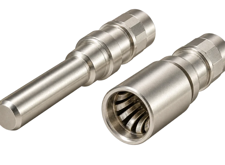
전기차 급속충전 커넥터 접점: 고전류를 받는 핀과 소켓의 구조
전기차 급속충전 커넥터 접점은 차량 인렛의 핀과 충전 플러그의 소켓이 만드는 고전류 인터페이스입니다. 눈에 잘 보이지 않는 접촉대, 도금과 케이블…
ID
18 10월 2026
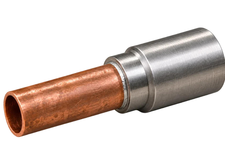
구리–스테인리스 이종 브레이징: 젖음·열간 간극·계면 내구성
구리–스테인리스 이종 브레이징 설계에서는 젖음, 열간 간극, 용가재와 공정 관리를 함께 검토해야 합니다.
ID
15 10월 2026

판금 루버 성형: 개구 형상·금형·압력손실을 연결하는 설계
루버는 판에 구멍을 많이 만드는 작업을 넘어, 절개한 재료를 원하는 방향으로 세워 공기의 통로와 패널의 구조를 함께 만드는 성형입니다.
ID
13 10월 2026
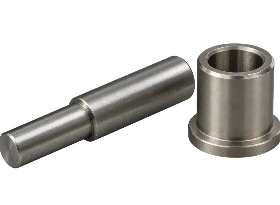
도금 공차 설계: 기능 치수·두께 분포·완성 검사
정밀 부품의 표면처리는 재료의 기능을 바꾸면서 조립 공간도 바꿉니다. 외경은 커지고 내경은 작아지며, 마스킹 경계와 국부 성장까지 상대 부품의 움직임에…
 ID
12 10월 2026

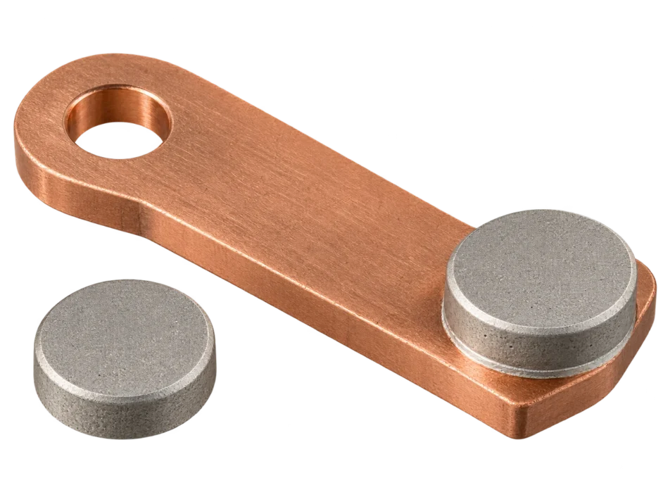
리벳 접점 조립품: 프레스 스프링·와이퍼 브러시의 설계와 품질관리
프레스 스프링과 와이퍼 브러시를 구성하는 리벳 접점 조립품의 구조·소재·리베팅 공정을 살펴보고, 접촉력·저항·마모를 연결해 설계와 품질관리의 핵심을 정리합니다.
