


PLATING TOLERANCE ENGINEERING
표면의 성장.
정밀한 맞물림.
도금 여유·기능 간극·두께 분포와 완성 검사
Coat.
Gauge.
Fit.
PLATING TOLERANCE ENGINEERING
피막의 두께에서
조립을 읽습니다.
바탕 치수·국부 성장·마스킹·측정과 판정 조건을 함께 검토합니다.
COATING · ALLOWANCE · CLEARANCE · GAUGING
Overview.
가공 치수와 표면 기능을 하나의 완성 상태로 연결합니다.
정밀 부품의 표면처리는 재료의 기능을 바꾸면서 조립 공간도 바꿉니다. 외경은 커지고 내경은 작아지며, 마스킹 경계와 국부 성장까지 상대 부품의 움직임에 영향을 줍니다. 도금 공차 설계는 가공 치수와 피막 두께를 하나의 완성 상태로 연결하는 일입니다.
축과 부시를 중심으로 치수 변화의 부호, 국부 두께, 나사 맞물림, 간극 계산과 측정 판단을 살펴봅니다. 명목 두께를 한 번 빼는 방식에서 나아가 허용된 끝값 조합과 실제 검사 조건까지 검토하면 가공·도금·조립 사이의 불일치를 줄일 수 있습니다.
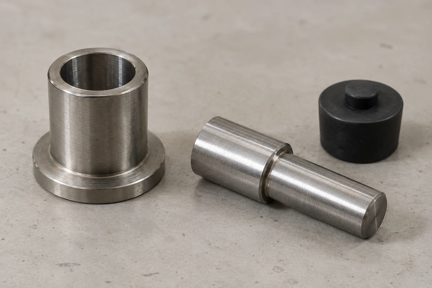
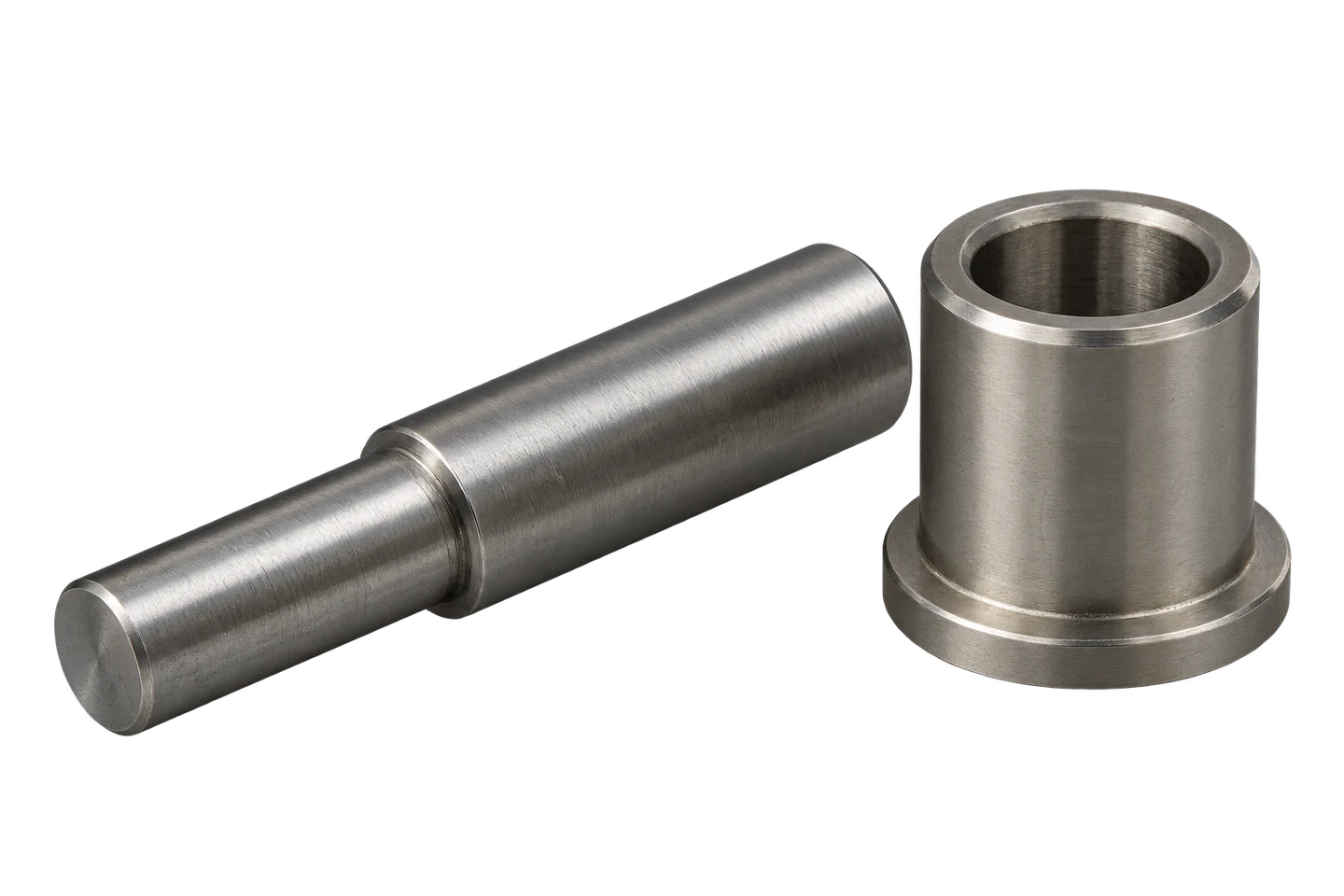
COMPONENT & MASK / 축·부시와 보호 플러그
Structure.
완성 상태와 치수 변화의 방향
01 / FUNCTIONAL STATE
완성 상태에서 공차를 시작합니다
도금 공차는 피막과 부품 치수가 동시에 만족해야 하는 설계 조건입니다.
표면처리 사양을 도면의 마지막 비고로 남기면 가공과 검사에서 서로 다른 완성품을 상상하기 쉽습니다. 안내 핀은 부시 안에서 움직여야 하고, 위치 결정 면은 체결 후 기준을 유지해야 합니다. 먼저 납품 상태의 기능과 허용 범위를 정한 다음, 그 상태를 만드는 가공·도금·후처리 순서를 거꾸로 검토하는 것이 효과적입니다.
같은 부품이라도 열처리 직후, 도금 직후, 연삭 후의 치수는 구별해야 합니다. 최소 피막 두께가 어느 공정에서 적용되는지 불분명하면 후가공으로 외경을 맞추고도 필요한 보호층을 잃을 수 있습니다. 검사 성적서는 수치뿐 아니라 공정 상태, 도면 개정과 기능면 식별자를 함께 가져야 판단의 대상이 일치합니다.
설계 검토에서는 상대 부품까지 한 쌍으로 다룹니다. 축만 처리하는 경우와 축·홀을 모두 처리하는 경우는 조립 여유의 소비량이 다릅니다. 외관면의 두께 평균을 중요한 안내면의 최대 두께로 대신할 수도 없습니다. 치수 요구, 표면 기능, 측정 가능한 위치를 하나의 기능면 목록에 연결하면 공정 간 책임이 명확해집니다.
기능면
미끄럼·위치·체결을 만드는 면 · 상대 부품과 허용 간극 지정
완성 상태
마지막 요구 공정까지 끝난 상태 · 도금·후가공 검사 시점 구별
이력
같은 요구를 추적하는 식별 정보 · 개정·공정·측정 위치 연결
완성 상태에서 공차를 시작합니다 — 실무 판단 기준
| 검토 항목 | 기술적 의미 | 검증·관리 기준 |
|---|---|---|
| 기능면 | 미끄럼·위치·체결을 만드는 면 | 상대 부품과 허용 간극 지정 |
| 완성 상태 | 마지막 요구 공정까지 끝난 상태 | 도금·후가공 검사 시점 구별 |
| 이력 | 같은 요구를 추적하는 식별 정보 | 개정·공정·측정 위치 연결 |
기능면
기술적 의미
미끄럼·위치·체결을 만드는 면
검증·관리 기준
상대 부품과 허용 간극 지정
완성 상태
기술적 의미
마지막 요구 공정까지 끝난 상태
검증·관리 기준
도금·후가공 검사 시점 구별
이력
기술적 의미
같은 요구를 추적하는 식별 정보
검증·관리 기준
개정·공정·측정 위치 연결
02 / SIGNED GROWTH
한 면의 성장과 지름 변화를 구별합니다
두께의 방향을 정하면 축·홀·슬롯의 변화 부호가 분명해집니다.
피막 두께 t는 보통 바탕 표면에 수직인 한쪽 층의 두께입니다. 원형 축에 균일하게 t가 더해지면 반지름은 t, 지름은 2t 증가합니다. 원형 홀의 안쪽 벽에 같은 층이 생기면 자유 공간은 줄어 지름이 2t 감소합니다. 이 관계는 금속 제거와 변형이 없고, 비교하는 단면의 피막이 균일하다는 기하 조건에서 성립합니다.
서로 마주 보는 평면에서는 양쪽 두께를 따로 쓰는 것이 더 일반적입니다. 슬롯 폭은 원래 폭에서 왼쪽과 오른쪽 피막을 각각 빼고, 판의 전체 두께는 앞뒤 층을 더합니다. 한 면만 마스킹된 형상에 무조건 2t를 적용하면 오차가 생깁니다. 곡면의 국부 두께 변화가 크면 단일 지름값과 실제 통과 가능한 공간도 구별해야 합니다.
단위는 계산 전에 하나로 통일합니다. 1 μm는 0.001 mm이고 1 μin은 0.0254 μm이므로, 200 μin은 5.08 μm입니다. 바탕의 치수를 mm로 놓고 피막 숫자만 μm 그대로 더하는 실수는 검토표에서 즉시 드러나야 합니다. 표면을 향한 법선 방향, 한쪽 두께와 양면 합산값을 도식과 열 제목에 명확히 구분합니다.
외경
균일 도금에서는 +2t · 반지름과 지름을 구별
내경·슬롯
마주 보는 층만큼 공간 감소 · 양쪽 두께와 마스킹 확인
단위
200 μin = 5.08 μm · 계산 입력을 동일 단위로 변환
두께의 방향을 정하면 축·홀·슬롯의 변화 부호가 분명해집니다.
외경
균일 도금에서는 +2t · 반지름과 지름을 구별
한 면의 성장과 지름 변화를 구별합니다 — 실무 판단 기준
| 검토 항목 | 기술적 의미 | 검증·관리 기준 |
|---|---|---|
| 외경 | 균일 도금에서는 +2t | 반지름과 지름을 구별 |
| 내경·슬롯 | 마주 보는 층만큼 공간 감소 | 양쪽 두께와 마스킹 확인 |
| 단위 | 200 μin = 5.08 μm | 계산 입력을 동일 단위로 변환 |
외경
기술적 의미
균일 도금에서는 +2t
검증·관리 기준
반지름과 지름을 구별
내경·슬롯
기술적 의미
마주 보는 층만큼 공간 감소
검증·관리 기준
양쪽 두께와 마스킹 확인
단위
기술적 의미
200 μin = 5.08 μm
검증·관리 기준
계산 입력을 동일 단위로 변환
Materials.
층 구성과 국부 성장의 조건
03 / COATING SYSTEM
층 구성과 공정 경로를 함께 선택합니다
기능층을 바꾸면 가공 여유와 후처리의 조건도 다시 검토해야 합니다.
치수에 기여하는 것은 마지막 겉층만이 아닙니다. 남아 있는 하도금, 확산 방지층, 기능 도금과 지정된 후처리를 공정 순서에 따라 구분합니다. 여러 금속층이 잔류한다면 최종 외형에는 그 합이 작용하지만, 중간 세정이나 활성화에서 제거된 바탕 금속은 반대 방향으로 작용합니다. 처음 가공한 치수에 명목 두께를 한 번 더하는 방식은 이 차이를 숨길 수 있습니다.
전해 도금은 부품 형상과 전극 배치가 국부 성장에 영향을 줍니다. 무전해 니켈은 외부 전류를 쓰지 않는다는 장점이 있지만, 용액이 닿고 교환되며 반응이 지속되는 조건까지 자동으로 같아지는 것은 아닙니다. 깊은 구멍과 좁은 홈은 명칭으로 균일성을 보장하기보다 실제 기능면의 두께 지도로 공정 적합성을 확인해야 합니다.
니켈·인 피막에서는 조성과 후열처리가 경도와 다른 특성에 영향을 줍니다. 원하는 기능을 위해 후처리를 추가했다면 치수 안정성과 재료 상태도 그 경로에서 확인해야 합니다. 공정 선택은 가장 균일하다는 인상이나 가장 얇은 숫자보다, 요구한 기능층을 최종 형상 안에 반복해서 남길 수 있는지를 기준으로 판단합니다.
잔류 층
최종 외형에 더해지는 층 · 층별 두께와 검사 시점 기록
전처리 제거
성장과 반대인 치수 변화 · 가공 직후와 처리 직전 구별
전해·무전해
서로 다른 분포 형성 원리 · 실제 형상에서 국부 검증
잔류 층
최종 외형에 더해지는 층 · 층별 두께와 검사 시점 기록
층 구성과 공정 경로를 함께 선택합니다 — 실무 판단 기준
| 검토 항목 | 기술적 의미 | 검증·관리 기준 |
|---|---|---|
| 잔류 층 | 최종 외형에 더해지는 층 | 층별 두께와 검사 시점 기록 |
| 전처리 제거 | 성장과 반대인 치수 변화 | 가공 직후와 처리 직전 구별 |
| 전해·무전해 | 서로 다른 분포 형성 원리 | 실제 형상에서 국부 검증 |
| 후열처리 | 특성과 형상에 함께 관여 | 납품 상태에서 치수 재확인 |
잔류 층
기술적 의미
최종 외형에 더해지는 층
검증·관리 기준
층별 두께와 검사 시점 기록
전처리 제거
기술적 의미
성장과 반대인 치수 변화
검증·관리 기준
가공 직후와 처리 직전 구별
전해·무전해
기술적 의미
서로 다른 분포 형성 원리
검증·관리 기준
실제 형상에서 국부 검증
후열처리
기술적 의미
특성과 형상에 함께 관여
검증·관리 기준
납품 상태에서 치수 재확인
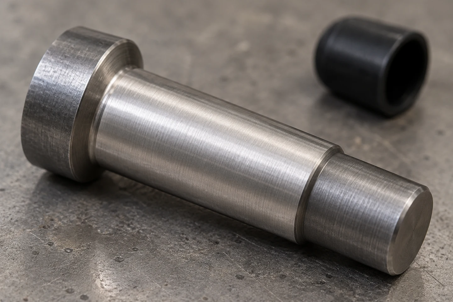
SURFACE TRANSITION / 가공면과 마스킹 경계
04 / LOCAL DISTRIBUTION
평균이 아닌 기능면의 분포를 읽습니다
가장 두꺼운 위치와 가장 얇은 위치는 서로 다른 실패를 만듭니다.
평균 두께가 목표에 도달해도 입구의 두꺼운 피막이 핀의 통과를 막을 수 있고, 안쪽의 얇은 층은 필요한 표면 기능을 충분히 확보하지 못할 수 있습니다. 따라서 대표 위치 한 곳의 값을 전체 면에 확장하지 않습니다. 끝단·중앙·깊이 방향과 상대 부품이 실제 지나가는 영역을 구분해 두께의 상한과 하한을 확인합니다.
차폐판이나 보조 전극은 전류 분포를 조절하는 설계 수단이지만 정해진 형상을 모든 부품에 그대로 적용하는 해법은 아닙니다. 차폐가 바뀌면 용액 흐름과 기체 배출도 달라질 수 있습니다. 전기장만 잘 맞춘 해석이 실제 성장까지 설명하는지는 시편과 실품의 여러 위치에서 확인하고, 맞지 않는 구역은 모델의 빠진 물리를 검토합니다.
양산 분포는 부품 하나의 둘레 방향뿐 아니라 랙의 위치와 배치 밀도에서도 달라질 수 있습니다. 같은 조건으로 취급할 범위를 먼저 정하고, 위치별로 대응되는 검사 결과를 모읍니다. 공정 평균을 줄여 최대 두께를 피하는 조치가 최소 피막을 훼손하는지 함께 확인해야 하며, 필요한 경우 형상·랙·공정 자체를 바꾸는 편이 합리적입니다.
가장 두꺼운 위치와 가장 얇은 위치는 서로 다른 실패를 만듭니다.
평균이 아닌 기능면의 분포를 읽습니다 — 실무 판단 기준
| 검토 항목 | 기술적 의미 | 검증·관리 기준 |
|---|---|---|
| 최대 두께 | 통과·조립 공간 제한 | 입구·모서리·맞물림 경로 검사 |
| 최소 두께 | 필요한 기능층의 하한 | 오목면·깊은 구역의 접근성 확보 |
| 보조 수단 | 분포를 바꾸는 공정 설계 | 시험과 해석의 국부 차이 검토 |
| 랙 위치 | 같은 로트 안의 조건 차이 | 배치·위치와 검사값 연결 |
최대 두께
기술적 의미
통과·조립 공간 제한
검증·관리 기준
입구·모서리·맞물림 경로 검사
최소 두께
기술적 의미
필요한 기능층의 하한
검증·관리 기준
오목면·깊은 구역의 접근성 확보
보조 수단
기술적 의미
분포를 바꾸는 공정 설계
검증·관리 기준
시험과 해석의 국부 차이 검토
랙 위치
기술적 의미
같은 로트 안의 조건 차이
검증·관리 기준
배치·위치와 검사값 연결
3D · 피막 성장과 축·홀의 간극
STRUCTURE & INTERFACEID SOLUTECH / 01
완성 조립
인터랙티브 3D를 준비하고 있습니다.
축과 부시를 같은 축에 조립합니다. 마스킹된 축 어깨가 부시 윗면에 닿는 상태를 표시합니다.
드래그·방향키: 회전 / + −: 확대·축소 / Home: 초기화피막 성장과 축·홀의 간극
도금 두께의 평균은 조립 간극의 끝값을 대신하지 않습니다.
Precision.
허용 폭과 나사 맞물림
05 / ALLOWANCE BUDGET
가공 공차와 피막 변동을 배분합니다
중심값의 보정과 허용 폭의 배분은 별개의 작업입니다.
외경의 최종 한계가 정해지면 도금 전 치수의 하한에는 최소 성장, 상한에는 최대 성장을 적용합니다. 균일한 피막만 고려한 경우 가공 치수의 허용 폭에 도금 두께 범위의 두 배를 더한 값이 최종 지름 범위가 됩니다. 최종 공차에서 남는 폭이 음수라면 작업자에게 더 정밀하게 하라고 요청할 단계가 아니라 설계 조건이 서로 맞지 않는 상태입니다.
평균 성장량을 정확히 알고 있어도 산포가 넓으면 끝값은 요구 밖으로 나갈 수 있습니다. 반대로 평균이 어긋난 공정은 산포를 줄여도 잘못된 위치에 모입니다. 치수 중심을 옮기는 조치와 분포 폭을 줄이는 조치를 구분하고, 변화가 어느 기능면의 최소 피막 또는 최대 외형을 제한하는지 확인해야 합니다.
통계적 합산을 쓰려면 같은 로트의 바탕 치수와 피막 결과를 연결한 데이터가 필요합니다. 공정 한계나 구매 사양의 ± 값을 근거 없이 표준편차로 변환하지 않습니다. 랙 위치와 욕 상태처럼 여러 부품에 공통으로 작용하는 변화가 있으면 독립 가정도 다시 검토해야 합니다. 초기 호환성 검토에서는 한계 조합을 먼저 확인하는 편이 명확합니다.
치수 중심
예상 성장의 위치 보정 · 공정 평균과 도면 목표 구별
허용 폭
가공 범위와 피막 범위의 합 · 음수 예산이면 조건 재설계
실측 데이터
공정 분포의 근거 · 부품·위치·로트 대응 유지
치수 중심
예상 성장의 위치 보정 · 공정 평균과 도면 목표 구별
가공 공차와 피막 변동을 배분합니다 — 실무 판단 기준
| 검토 항목 | 기술적 의미 | 검증·관리 기준 |
|---|---|---|
| 치수 중심 | 예상 성장의 위치 보정 | 공정 평균과 도면 목표 구별 |
| 허용 폭 | 가공 범위와 피막 범위의 합 | 음수 예산이면 조건 재설계 |
| 실측 데이터 | 공정 분포의 근거 | 부품·위치·로트 대응 유지 |
| 상관 | 공통 조건에 따른 동시 변화 | 독립 합산의 전제 확인 |
치수 중심
기술적 의미
예상 성장의 위치 보정
검증·관리 기준
공정 평균과 도면 목표 구별
허용 폭
기술적 의미
가공 범위와 피막 범위의 합
검증·관리 기준
음수 예산이면 조건 재설계
실측 데이터
기술적 의미
공정 분포의 근거
검증·관리 기준
부품·위치·로트 대응 유지
상관
기술적 의미
공통 조건에 따른 동시 변화
검증·관리 기준
독립 합산의 전제 확인
06 / THREADED INTERFACES
나사는 지름뿐 아니라 맞물림을 봅니다
나사산의 경사면에서는 두께의 기하 효과가 원통면과 다릅니다.
이상적인 60° 나사 양쪽 플랭크에 수직 두께 t가 균일하게 형성되면 외나사의 유효지름은 약 4t 커지고 암나사는 약 4t 작아집니다. 이 계수는 플랭크의 기울기에서 나오며, 외경·골지름·길이 전체를 같은 비율로 바꾸라는 뜻이 아닙니다. 피치·리드·산형 오차나 국부 두께 차이가 큰 실제 나사는 단순 오프셋만으로 기능을 판정할 수 없습니다.
도금 후 나사가 들어간다는 사실만으로 필요한 체결 성능을 확인한 것은 아닙니다. 도금 전 여유를 과하게 확보하면 유효 맞물림이 줄 수 있고, 최종 윤활·표면 상태가 바뀌면 같은 조임 토크에서 형성되는 축력도 달라질 수 있습니다. 치수 등급, 최종 게이지 조건, 상대 나사와 조립 조건을 동일한 승인 범위에서 관리합니다.
긴 외나사에서는 끝부분과 중앙의 두께가 다를 수 있어 중앙의 보호층을 늘리려는 조치가 끝단 통과성을 악화시킬 수 있습니다. 전 길이 평균이나 한 번의 조립 느낌으로 처리하지 말고 기능 게이지와 지정 위치의 피막 검사를 함께 적용합니다. 도금 후 탭으로 무조건 정리하는 조치는 필요한 층을 제거할 수 있으므로 후가공 사양과 잔류 두께까지 먼저 정해야 합니다.
60° 플랭크
이상적인 유효지름 변화 약 4t · 다른 치수에 일괄 적용 금지
최종 게이지
완성 나사의 기능 경계 · 산형·리드 등 복합 영향 확인
끝단·중앙
국부 두께의 서로 다른 영향 · 맞물림과 최소 피막 동시 검사
60° 플랭크
이상적인 유효지름 변화 약 4t · 다른 치수에 일괄 적용 금지
나사는 지름뿐 아니라 맞물림을 봅니다 — 실무 판단 기준
| 검토 항목 | 기술적 의미 | 검증·관리 기준 |
|---|---|---|
| 60° 플랭크 | 이상적인 유효지름 변화 약 4t | 다른 치수에 일괄 적용 금지 |
| 최종 게이지 | 완성 나사의 기능 경계 | 산형·리드 등 복합 영향 확인 |
| 끝단·중앙 | 국부 두께의 서로 다른 영향 | 맞물림과 최소 피막 동시 검사 |
| 후가공 | 형상 회복과 피막 제거 | 잔류 층과 체결 조건 재승인 |
60° 플랭크
기술적 의미
이상적인 유효지름 변화 약 4t
검증·관리 기준
다른 치수에 일괄 적용 금지
최종 게이지
기술적 의미
완성 나사의 기능 경계
검증·관리 기준
산형·리드 등 복합 영향 확인
끝단·중앙
기술적 의미
국부 두께의 서로 다른 영향
검증·관리 기준
맞물림과 최소 피막 동시 검사
후가공
기술적 의미
형상 회복과 피막 제거
검증·관리 기준
잔류 층과 체결 조건 재승인
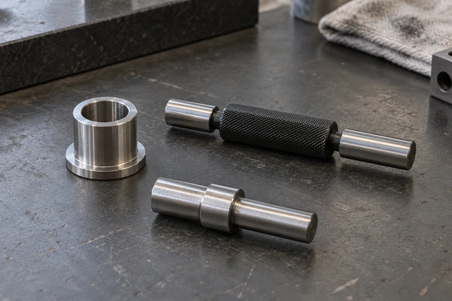
FINAL INSPECTION / 부시와 한계 플러그 게이지
Motion.
마스킹과 조립 간극의 계산
07 / MASKING & RACKING
마스킹 경계도 기능면에 포함합니다
가려진 면과 노출된 면의 경계가 상대 부품의 이동을 방해할 수 있습니다.
모든 면에 같은 피막을 적용하는 설계가 항상 유리하지는 않습니다. 치수에 민감한 구멍을 마스킹할 수 있다면 간극 예산이 달라지지만, 그 면에 필요했던 내식성과 접촉 기능도 함께 검토해야 합니다. 도금 제외를 공정 편의로 결정하지 말고 기능 요구가 허용하는지 확인한 뒤 도면의 면 식별자와 연결합니다.
마스킹 끝은 단순한 색상 경계가 아닙니다. 피막의 단차, 미세한 들뜸이나 잔류물이 씰·베어링·슬라이딩 부품의 통과 경로에 들어오면 조립 상태가 달라질 수 있습니다. 경계 위치와 허용 침범량을 정하고, 검사 방향에서 가려지는 부분이 없도록 접근성을 검토합니다. 보호 캡이나 플러그의 반복 사용 조건도 공정 관리 대상입니다.
랙 접촉점은 고정과 전기적 연결을 위해 필요할 수 있지만, 자국이 남는 면을 임의로 바꾸면 외관과 기능의 승인 범위가 달라집니다. 접촉 허용 구역, 부품 방향, 용액 배출 경로를 함께 정의합니다. 초도품에서 확인한 조건을 반복 생산으로 넘길 때에는 마스킹과 랙 배치 사진을 공정 기록에 남기는 것이 유용합니다.
제외 면
간극과 표면 기능의 변경 · 도면에서 면과 요구를 연결
경계 위치
단차·잔류물의 통과 영향 · 슬라이딩·씰 경로와 분리
랙 접촉
고정·전류 연결과 자국 · 허용 구역과 방향을 지정
가려진 면과 노출된 면의 경계가 상대 부품의 이동을 방해할 수 있습니다.
제외 면
간극과 표면 기능의 변경 · 도면에서 면과 요구를 연결
마스킹 경계도 기능면에 포함합니다 — 실무 판단 기준
| 검토 항목 | 기술적 의미 | 검증·관리 기준 |
|---|---|---|
| 제외 면 | 간극과 표면 기능의 변경 | 도면에서 면과 요구를 연결 |
| 경계 위치 | 단차·잔류물의 통과 영향 | 슬라이딩·씰 경로와 분리 |
| 랙 접촉 | 고정·전류 연결과 자국 | 허용 구역과 방향을 지정 |
| 공정 재현 | 초도 조건의 반복 유지 | 마스크·배치·배출 조건 기록 |
제외 면
기술적 의미
간극과 표면 기능의 변경
검증·관리 기준
도면에서 면과 요구를 연결
경계 위치
기술적 의미
단차·잔류물의 통과 영향
검증·관리 기준
슬라이딩·씰 경로와 분리
랙 접촉
기술적 의미
고정·전류 연결과 자국
검증·관리 기준
허용 구역과 방향을 지정
공정 재현
기술적 의미
초도 조건의 반복 유지
검증·관리 기준
마스크·배치·배출 조건 기록
3D · 완성 홀의 플러그 게이지 검사
PROCESS & VALIDATIONID SOLUTECH / 02
통과측 삽입
인터랙티브 3D를 준비하고 있습니다.
통과측이 기능 길이 안으로 들어가는 관계를 확인합니다. 게이지 통과만으로 최소 피막 두께까지 증명되는 것은 아닙니다.
드래그·방향키: 회전 / + −: 확대·축소 / Home: 초기화완성 홀의 플러그 게이지 검사
08 / CLEARANCE CALCULATION
축과 홀을 함께 계산합니다
양쪽을 도금하면 두 부품의 피막이 모두 조립 간극을 소비합니다.
계산 예에서 도금 전 축 지름은 19.970 ± 0.005 mm, 홀 지름은 20.030 ± 0.005 mm로 둡니다. 축의 한 면 두께는 0.008–0.012 mm, 홀의 한 면 두께는 0.006–0.010 mm입니다. 균일한 원형 피막과 강체를 가정하고 전처리 제거·형상 오차·온도 변화를 제외하면, 최종 축은 19.981–19.999 mm이고 홀은 20.005–20.023 mm가 됩니다.
지름 간극은 최종 홀에서 최종 축을 뺀 값입니다. 가장 작은 홀과 가장 큰 축을 조합하면 0.006 mm, 가장 큰 홀과 가장 작은 축을 조합하면 0.042 mm입니다. 중심값으로 계산한 0.024 mm만 보면 요구 간극 0.010–0.040 mm에 들어가지만, 허용된 끝값 조합은 양쪽에서 요구를 벗어납니다. 한 부품의 평균 두께만 조정해서는 이 범위 문제를 해결했다고 볼 수 없습니다.
가공 공차를 두 부품 모두 ±0.003 mm로 줄이고 피막 범위를 유지하면 계산 간극은 0.010–0.038 mm로 바뀝니다. 다만 하한이 요구 경계에 바로 닿으므로 측정 불확도와 실제 형상 오차를 위한 여유까지 확보한 것은 아닙니다. 이 수치는 도면을 검토하는 예제이며, 생산 합격 기준은 측정 방법·공정 데이터·판정 규칙과 함께 확정해야 합니다. 동심 상태에서의 반지름 간극은 이 지름 간극의 절반입니다.
C_f = D_b0 − D_s0 − 2(t_b + t_s)
C_f: 완성 지름 간극 · D_b0/D_s0: 도금 전 홀/축 지름 · t_b/t_s: 각 부품의 한 면 두께. 균일한 원형 피막, 강체, 동일 온도를 가정하며 전처리 제거와 형상 오차는 제외합니다.
축 완성 지름
19.981–19.999 mm · 가공 하한+최소 성장 / 상한+최대 성장
축과 홀을 함께 계산합니다 — 실무 판단 기준
| 검토 항목 | 기술적 의미 | 검증·관리 기준 |
|---|---|---|
| 축 완성 지름 | 19.981–19.999 mm | 가공 하한+최소 성장 / 상한+최대 성장 |
| 홀 완성 지름 | 20.005–20.023 mm | 최소 홀−최대 피막 / 최대 홀−최소 피막 |
| 지름 간극 | 0.006–0.042 mm | 중심값 0.024 mm만으로 승인 불가 |
| 가공 공차 개선 예 | ±0.003 mm → 간극 0.010–0.038 mm | 경계 판정과 형상 영향은 별도 검토 |
축 완성 지름
기술적 의미
19.981–19.999 mm
검증·관리 기준
가공 하한+최소 성장 / 상한+최대 성장
홀 완성 지름
기술적 의미
20.005–20.023 mm
검증·관리 기준
최소 홀−최대 피막 / 최대 홀−최소 피막
지름 간극
기술적 의미
0.006–0.042 mm
검증·관리 기준
중심값 0.024 mm만으로 승인 불가
가공 공차 개선 예
기술적 의미
±0.003 mm → 간극 0.010–0.038 mm
검증·관리 기준
경계 판정과 형상 영향은 별도 검토
필요한 기능층과 허용되는 외형은 같은 완성 상태에서 만나야 합니다.
Interface.
형상·재료 상태와 측정
09 / SHAPE & MATERIAL STATE
두께 보정 뒤에도 형상은 남습니다
지름 계산에 포함하지 않은 변형과 재료 위험을 별도로 확인합니다.
도금 전후의 평균 지름이 맞더라도 얇은 벽이나 긴 부품이 휘면 실제 통과성과 기준 위치는 달라집니다. 비대칭 피막과 잔류 응력, 고정 상태, 후열처리를 함께 검토하고 원통도·직진도·평면도처럼 기능에 필요한 형상 항목을 선택합니다. 한 단면의 두 점 측정은 길이 전체의 통과 외형을 보증하지 않습니다.
수 마이크로미터의 여유를 판단할 때에는 측정 온도와 부품의 열평형도 치수 조건입니다. 부품과 게이지의 재질이 다르면 같은 실내 온도에서도 보정의 영향이 달라질 수 있습니다. 온도계 숫자 하나로 충분하다고 보지 말고 부품 내부의 안정화와 열팽창계수의 불확도를 포함해 측정 계획을 세웁니다.
고강도 강 부품의 일부 전처리와 전해 공정에서는 수소 취성 위험을 검토해야 합니다. 치수가 맞거나 외관이 깨끗하다는 이유로 그 위험이 해소되지는 않습니다. 재료 강도와 열처리 상태, 공정 경로, 적용 규격과 승인된 위험 저감 절차를 연결해 검토하며, 모든 재료에 같은 베이킹 온도와 시간을 적용하는 방식은 피해야 합니다.
지름 계산에 포함하지 않은 변형과 재료 위험을 별도로 확인합니다.
형상
휨·원통도·기준 위치 변화 · 실제 맞물림 길이와 지지 조건 확인
두께 보정 뒤에도 형상은 남습니다 — 실무 판단 기준
| 검토 항목 | 기술적 의미 | 검증·관리 기준 |
|---|---|---|
| 형상 | 휨·원통도·기준 위치 변화 | 실제 맞물림 길이와 지지 조건 확인 |
| 열 상태 | 부품·게이지의 팽창 차이 | 평형·재질·보정 불확도 관리 |
| 잔류 응력 | 얇거나 비대칭인 형상의 변형 | 후처리까지 포함한 완성 상태 검사 |
| 재료 위험 | 고강도 강의 수소 취성 등 | 승인된 재료·공정별 절차 적용 |
형상
기술적 의미
휨·원통도·기준 위치 변화
검증·관리 기준
실제 맞물림 길이와 지지 조건 확인
열 상태
기술적 의미
부품·게이지의 팽창 차이
검증·관리 기준
평형·재질·보정 불확도 관리
잔류 응력
기술적 의미
얇거나 비대칭인 형상의 변형
검증·관리 기준
후처리까지 포함한 완성 상태 검사
재료 위험
기술적 의미
고강도 강의 수소 취성 등
검증·관리 기준
승인된 재료·공정별 절차 적용
10 / MEASUREMENT STRATEGY
피막 두께와 완성 치수를 따로 증명합니다
두 측정은 서로 돕지만 같은 요구를 대신하지 않습니다.
X선 형광 방식은 적절한 층 구성과 보정 모델 안에서 피막을 평가하는 데 유용합니다. 그러나 두께 환산에는 밀도와 조성의 가정이 들어가며, 기판과 여러 층의 조합에 따라 민감도와 유효 범위가 달라집니다. 평평한 표준편에서 확인한 결과를 곡면이나 작은 구멍의 가장자리로 바로 확장하지 말고 실제 조사 면적·각도·초점 조건을 검토합니다.
단면 관찰은 선택한 위치의 층 구조와 두께를 직접 비교하는 데 도움이 됩니다. 절단·연마에서 경계가 기울거나 가장자리가 변형되면 읽는 값도 달라질 수 있으므로 준비 상태와 측정 방향을 확인합니다. 현미경의 한 시야가 전체 부품의 최소 두께를 대표하지는 않습니다. 깊이와 둘레에 따라 필요한 위치를 선정하고 비파괴 측정 결과와 연결합니다.
완성 치수는 기능에 맞는 외측·내측 측정기와 게이지로 별도 확인합니다. 도금 전후 차이를 두께로 환산하려면 같은 위치와 방향, 같은 열 상태를 대응시켜야 하며 전처리 제거와 형상 변화도 분리해야 합니다. 좁은 구멍이나 작은 홈처럼 측정 접근이 어려운 곳은 생산 후에 고민하기보다 설계 단계에서 접근면이나 검증 시편을 준비합니다.
XRF
층·조성·밀도 모델의 영향 · 실제 형상과 보정 조건 일치
단면 관찰
지정 위치의 국부 두께 · 준비 상태와 위치 대표성 확인
완성 치수
조립에 쓰이는 최종 형상 · 기능 길이·방향·온도 관리
XRF
층·조성·밀도 모델의 영향 · 실제 형상과 보정 조건 일치
피막 두께와 완성 치수를 따로 증명합니다 — 실무 판단 기준
| 검토 항목 | 기술적 의미 | 검증·관리 기준 |
|---|---|---|
| XRF | 층·조성·밀도 모델의 영향 | 실제 형상과 보정 조건 일치 |
| 단면 관찰 | 지정 위치의 국부 두께 | 준비 상태와 위치 대표성 확인 |
| 완성 치수 | 조립에 쓰이는 최종 형상 | 기능 길이·방향·온도 관리 |
| 측정 접근 | 구멍·홈의 검사 가능성 | 설계 때 접근과 시편 계획 |
XRF
기술적 의미
층·조성·밀도 모델의 영향
검증·관리 기준
실제 형상과 보정 조건 일치
단면 관찰
기술적 의미
지정 위치의 국부 두께
검증·관리 기준
준비 상태와 위치 대표성 확인
완성 치수
기술적 의미
조립에 쓰이는 최종 형상
검증·관리 기준
기능 길이·방향·온도 관리
측정 접근
기술적 의미
구멍·홈의 검사 가능성
검증·관리 기준
설계 때 접근과 시편 계획
Validation.
경계 판정과 반복 생산
11 / ACCEPTANCE DECISION
경계값에는 판정 규칙이 필요합니다
측정값, 측정 불확도와 제품 허용 범위를 구분해야 합니다.
검사값이 상한 바로 아래에 있다는 사실만으로 언제나 같은 합격 판단이 나오지는 않습니다. 측정 불확도를 어떻게 취급할지와 수용 구간을 어디에 둘지 사전에 합의해야 합니다. 제품의 설계 허용 범위와 검사에서 사용할 수용 범위는 관련되어 있지만 동일하다고 자동으로 가정할 수 없습니다. 경계 근처 결과를 공급자와 고객이 서로 다르게 해석하지 않도록 판정 방법을 기록합니다.
같은 부품을 반복 측정하면 단기 반복성은 보이지만 보정 표준, 온도, 접촉력과 위치 선정에서 생기는 영향이 모두 사라지지는 않습니다. 검사 장비가 표시하는 자릿수와 실제 판정 능력도 구별해야 합니다. 서로 다른 측정 방법을 비교할 때에는 평균 차이뿐 아니라 측정 대상의 정의와 국부 위치가 같은지 먼저 확인합니다.
검사 수량은 로트 전체의 위험과 연결해 정해야 합니다. 랙 중앙에서 고른 몇 개가 끝단 위치의 두꺼운 피막을 대표한다고 볼 수는 없습니다. 공정 위치별 변동과 중요한 기능면의 실패 형태를 반영해 샘플링을 구성하고, 공정 변경이나 이상 경향이 나타나면 검사 범위를 조정합니다. 전수 검사라고 해도 측정하지 않은 면의 품질까지 자동으로 확인된 것은 아닙니다.
제품 한계
설계가 허용하는 범위 · 기능과 상대 부품에서 결정
수용 규칙
불확도를 고려한 검사 판단 · 공급자·고객 간 사전 합의
반복성
단기 측정의 변동 · 보정·온도 등 다른 영향도 검토
측정값, 측정 불확도와 제품 허용 범위를 구분해야 합니다.
제품 한계
설계가 허용하는 범위 · 기능과 상대 부품에서 결정
경계값에는 판정 규칙이 필요합니다 — 실무 판단 기준
| 검토 항목 | 기술적 의미 | 검증·관리 기준 |
|---|---|---|
| 제품 한계 | 설계가 허용하는 범위 | 기능과 상대 부품에서 결정 |
| 수용 규칙 | 불확도를 고려한 검사 판단 | 공급자·고객 간 사전 합의 |
| 반복성 | 단기 측정의 변동 | 보정·온도 등 다른 영향도 검토 |
| 샘플링 | 로트·위치별 위험의 확인 | 중요 면과 변경 조건을 반영 |
제품 한계
기술적 의미
설계가 허용하는 범위
검증·관리 기준
기능과 상대 부품에서 결정
수용 규칙
기술적 의미
불확도를 고려한 검사 판단
검증·관리 기준
공급자·고객 간 사전 합의
반복성
기술적 의미
단기 측정의 변동
검증·관리 기준
보정·온도 등 다른 영향도 검토
샘플링
기술적 의미
로트·위치별 위험의 확인
검증·관리 기준
중요 면과 변경 조건을 반영
12 / PRODUCTION RELEASE
초도 검증을 반복 가능한 조건으로 남깁니다
가공·도금·검사 자료가 같은 개정을 가리킬 때 생산 승인이 명확해집니다.
초도 검토에는 완성 치수 도면과 도금 전 가공 도면을 함께 준비합니다. 기능면별 최소·최대 피막, 층 구성, 마스킹, 랙 허용 구역과 후처리 순서를 연결하고, 어디에서 어떤 장비로 측정할지 정합니다. 요구가 충돌하는 구역은 시제품 결과를 기다리기 전에 간극 예산과 접근성 검토에서 먼저 드러내는 것이 좋습니다.
승인 자료에는 부품별 전후 치수와 위치별 피막 결과를 대응시킵니다. 평균이나 대표 사진만 남기면 후속 로트에서 어떤 조건이 달라졌는지 찾기 어렵습니다. 재료, 도면 개정, 외주 공정 경로와 검사 방법이 바뀌었을 때 재검토할 항목을 정하고, 동일 조건으로 묶을 수 없는 변경은 새로 검증합니다.
도금 후 연삭이나 재도금은 치수를 회복하는 작업이면서 피막과 모재를 다시 바꾸는 작업입니다. 남은 층의 최소 두께, 기능면의 형상, 재처리 횟수와 재료 위험을 승인 범위에서 확인해야 합니다. 아이디솔루텍과 도금 적용 부품을 검토할 때에는 최종 조립 조건과 표면 기능을 함께 제공하면 가공 여유·공정 경로·완성 검사 사이의 판단을 더 명확하게 연결할 수 있습니다.
입력 도면
완성 상태와 도금 전 상태 · 같은 개정과 면 식별자 사용
초도 기록
치수·피막·위치의 대응 · 부품별 전후 결과 유지
변경 관리
재료·랙·경로·검사의 변화 · 영향 범위에 맞춰 재검증
입력 도면
완성 상태와 도금 전 상태 · 같은 개정과 면 식별자 사용
초도 검증을 반복 가능한 조건으로 남깁니다 — 실무 판단 기준
| 검토 항목 | 기술적 의미 | 검증·관리 기준 |
|---|---|---|
| 입력 도면 | 완성 상태와 도금 전 상태 | 같은 개정과 면 식별자 사용 |
| 초도 기록 | 치수·피막·위치의 대응 | 부품별 전후 결과 유지 |
| 변경 관리 | 재료·랙·경로·검사의 변화 | 영향 범위에 맞춰 재검증 |
| 재처리 | 잔류 층과 모재의 재평가 | 승인된 후가공·재도금 범위 확인 |
입력 도면
기술적 의미
완성 상태와 도금 전 상태
검증·관리 기준
같은 개정과 면 식별자 사용
초도 기록
기술적 의미
치수·피막·위치의 대응
검증·관리 기준
부품별 전후 결과 유지
변경 관리
기술적 의미
재료·랙·경로·검사의 변화
검증·관리 기준
영향 범위에 맞춰 재검증
재처리
기술적 의미
잔류 층과 모재의 재평가
검증·관리 기준
승인된 후가공·재도금 범위 확인
정밀한 판정은 측정 위치와 공정 상태를 일치시키는 데서 시작됩니다.
개발 상담 · Contact
연락처 · Get in Touch
기술 협의 · Engineering Consultation
도면과 사양을 기준으로 소재·가공·표면처리,
주요 품질 항목과 공급 조건을 함께 검토합니다.
We review drawings and specifications to define materials, manufacturing methods, surface finishes, key quality requirements, and supply conditions.
주요 품질 항목과 공급 조건을 함께 검토합니다.
We review drawings and specifications to define materials, manufacturing methods, surface finishes, key quality requirements, and supply conditions.
개발 의뢰하기 · Development Inquiry
PLATING TOLERANCE ENGINEERING
Read the Fit
Through the Coating.
Review substrate size, local growth, masking, measurement and decision conditions together.
COATING · ALLOWANCE · CLEARANCE · GAUGING
ENGLISH EDITION
Surface Growth.
Precision Fit.
Coating allowance, functional clearance, thickness distribution and final inspection
Connect machined dimensions and surface function to one finished state.
Surface finishing changes both material function and assembly space. External diameters grow, bores shrink, and masking transitions or local build-up can alter how mating parts move. Plating tolerance design connects machined dimensions and coating thickness to one defined finished state.
Using a shaft and bushing, this article examines signed dimensional change, local thickness, thread engagement, clearance calculations and inspection decisions. Reviewing permitted extreme combinations and measurement conditions helps align machining, plating and assembly beyond a single nominal-thickness offset.
COMPONENT & MASK / Shaft, bushing and protective plug
Structure.
Finished state and signed dimensional change
01 / FUNCTIONAL STATE
Start Tolerances at the Finished State
Coating tolerance requires the deposit and the component geometry to satisfy their requirements together.
A finishing note added after the dimensional design can leave machining and inspection working toward different end states. A guide pin must move through its bushing; a locating face must retain its position after fastening. Define the delivered function and its allowable window, then work backward through machining, deposition and finishing operations.
Dimensions after heat treatment, deposition and grinding are different measurands. If the stage at which minimum thickness applies is unspecified, a ground diameter may conform while the protective layer is inadequate. Inspection records need the process stage, drawing revision and functional-surface identifier as well as the numerical result.
Review the mating pair together. Coating only the shaft consumes a different clearance allowance from coating both shaft and bore. An average measured on a cosmetic face cannot stand in for the maximum deposit on a guiding surface. A functional-surface register should connect geometry, coating purpose and accessible measurement locations.
Functional surface
Creates sliding, location or fastening. Identify mate and clearance limits
Finished state
All specified final operations completed. Separate deposition and post-machining inspection
Traceability
Identity linking the same requirement. Connect revision, operation and measurement site
Start Tolerances at the Finished State — Review Criteria
| Review item | Engineering significance | Verification or control |
|---|---|---|
| Functional surface | Creates sliding, location or fastening | Identify mate and clearance limits |
| Finished state | All specified final operations completed | Separate deposition and post-machining inspection |
| Traceability | Identity linking the same requirement | Connect revision, operation and measurement site |
Functional surface
Engineering significance
Creates sliding, location or fastening
Verification or control
Identify mate and clearance limits
Finished state
Engineering significance
All specified final operations completed
Verification or control
Separate deposition and post-machining inspection
Traceability
Engineering significance
Identity linking the same requirement
Verification or control
Connect revision, operation and measurement site
02 / SIGNED GROWTH
Distinguish Surface Growth from Diameter Change
Defining the growth direction makes the signs for shafts, bores and slots explicit.
Thickness t is normally the local layer measured normal to the substrate. A uniform layer increases a round shaft radius by t and its diameter by 2t; an internal deposit reduces a round bore diameter by 2t. These are geometric relations for the compared section, without substrate removal, deformation or nonuniform deposition.
For opposing flat surfaces, retaining separate thickness terms is more general. A slot loses the deposits on its left and right walls; a plate gains the deposits on its two faces. Applying 2t to a selectively masked part is incorrect. Strongly nonuniform coatings also separate a measured diameter from the actual space available for passage.
Convert units before combining terms: 1 μm is 0.001 mm, and 1 μin is 0.0254 μm, so 200 μin equals 5.08 μm. A calculation sheet should expose any addition of an unconverted micrometre number to a millimetre dimension. Distinguish surface-normal thickness, one-sided allowance and the combined change across opposing surfaces.
External diameter
Uniform coating gives +2t. Distinguish radius and diameter
Bore or slot
Opposing deposits consume space. Check each side and masking
Units
200 μin = 5.08 μm. Convert all inputs to one unit
Defining the growth direction makes the signs for shafts, bores and slots explicit.
External diameter
Uniform coating gives +2t. Distinguish radius and diameter
Distinguish Surface Growth from Diameter Change — Review Criteria
| Review item | Engineering significance | Verification or control |
|---|---|---|
| External diameter | Uniform coating gives +2t | Distinguish radius and diameter |
| Bore or slot | Opposing deposits consume space | Check each side and masking |
| Units | 200 μin = 5.08 μm | Convert all inputs to one unit |
External diameter
Engineering significance
Uniform coating gives +2t
Verification or control
Distinguish radius and diameter
Bore or slot
Engineering significance
Opposing deposits consume space
Verification or control
Check each side and masking
Units
Engineering significance
200 μin = 5.08 μm
Verification or control
Convert all inputs to one unit
Materials.
Layer systems and local growth conditions
03 / COATING SYSTEM
Choose the Layer Stack and Process Route Together
Changing a functional layer also changes the allowance and post-treatment review.
The outermost layer is not the only contributor to size. Identify retained underplates, diffusion barriers, functional deposits and specified finishing steps in sequence. Retained metallic layers accumulate, while substrate removed during preparation acts in the opposite direction. Adding one nominal thickness to the original machined size can conceal this distinction.
Electrolytic growth responds to component geometry and electrode arrangement. Electroless nickel avoids externally imposed current distribution, but does not automatically equalize wetting, solution exchange or reaction conditions. For deep bores and narrow grooves, demonstrate suitability with a thickness map of the functional surfaces instead of relying on the process name.
Composition and subsequent heat treatment affect the properties of nickel-phosphorus deposits. If a thermal step is needed for the intended function, verify dimensions and substrate condition after that route. Select a process for its ability to leave the required functional coating within the final geometry repeatedly, rather than for a generic uniformity claim.
Retained layers
Layers contributing to final geometry. Record thickness and inspection stage
Preparation removal
Dimensional change opposite to growth. Distinguish machined and prepared states
Electrolytic/electroless
Different distribution mechanisms. Validate locally on the real geometry
Retained layers
Layers contributing to final geometry. Record thickness and inspection stage
Choose the Layer Stack and Process Route Together — Review Criteria
| Review item | Engineering significance | Verification or control |
|---|---|---|
| Retained layers | Layers contributing to final geometry | Record thickness and inspection stage |
| Preparation removal | Dimensional change opposite to growth | Distinguish machined and prepared states |
| Electrolytic/electroless | Different distribution mechanisms | Validate locally on the real geometry |
| Post heat treatment | Affects properties and geometry | Recheck the delivered state |
Retained layers
Engineering significance
Layers contributing to final geometry
Verification or control
Record thickness and inspection stage
Preparation removal
Engineering significance
Dimensional change opposite to growth
Verification or control
Distinguish machined and prepared states
Electrolytic/electroless
Engineering significance
Different distribution mechanisms
Verification or control
Validate locally on the real geometry
Post heat treatment
Engineering significance
Affects properties and geometry
Verification or control
Recheck the delivered state
SURFACE TRANSITION / Machined surface and masking boundary
04 / LOCAL DISTRIBUTION
Read the Distribution on the Functional Surface
The thickest and thinnest locations produce different failure modes.
An acceptable mean can coexist with an entrance deposit that blocks a pin and an internal region with insufficient coating. Do not extend one convenient measurement to the whole surface. Separate ends, mid-length, depth and the actual mating path, then assess upper and lower local bounds against their respective functions.
Shields and auxiliary electrodes are design tools, not universal shapes that can be transferred unchanged between parts. They may also alter flow and gas release. Check whether an electrical-field prediction explains measured growth at several locations on coupons and production geometry; persistent local disagreement may indicate missing transport physics.
Production variation can occur around a part and across rack positions or loading arrangements. Define the conditions treated as equivalent and retain location-matched results. Lowering the process mean to avoid excessive build-up may violate minimum thickness elsewhere; changing the geometry, rack or process can be more effective than shifting the target alone.
The thickest and thinnest locations produce different failure modes.
Read the Distribution on the Functional Surface — Review Criteria
| Review item | Engineering significance | Verification or control |
|---|---|---|
| Maximum thickness | Restricts passage or assembly | Inspect entrances, edges and mating paths |
| Minimum thickness | Lower bound for coating function | Reach recessed and deep regions |
| Distribution controls | Process design changes growth | Compare local experiments and predictions |
| Rack position | Conditions vary within a lot | Link loading position to measurements |
Maximum thickness
Engineering significance
Restricts passage or assembly
Verification or control
Inspect entrances, edges and mating paths
Minimum thickness
Engineering significance
Lower bound for coating function
Verification or control
Reach recessed and deep regions
Distribution controls
Engineering significance
Process design changes growth
Verification or control
Compare local experiments and predictions
Rack position
Engineering significance
Conditions vary within a lot
Verification or control
Link loading position to measurements
3D · Coating Growth and Shaft–Bore Clearance
STRUCTURE & INTERFACEID SOLUTECH / 01
Finished assembly
Preparing interactive 3D.
Assemble the coaxial pair. The masked shaft shoulder seats on the top of the bushing.
Drag / arrow keys: rotate · + −: zoom · Home: resetCoating Growth and Shaft–Bore Clearance
Mean coating thickness does not represent the clearance extremes.
Precision.
Tolerance allocation and thread engagement
05 / ALLOWANCE BUDGET
Allocate Machining and Coating Variation
Correcting the centre and allocating the tolerance width are separate tasks.
For an external diameter, pair the substrate lower limit with minimum growth and the upper limit with maximum growth. Under the uniform-layer model, final diameter range equals the machining range plus twice the coating-thickness range. A negative machining budget indicates incompatible requirements, not a request that can be solved by greater operator care.
Knowing the mean build-up accurately does not protect the extremes when the spread is wide. Conversely, reducing spread around the wrong centre leaves a biased process. Separate centring actions from variation reduction, and identify which local minimum coating or maximum envelope constrains each proposed change.
Statistical combination requires paired substrate and coating data from the relevant production populations. Specification limits are not automatically standard deviations. Shared effects such as rack position and bath condition also challenge independence assumptions. For an initial interchangeability review, the permitted extreme combinations provide a clear starting point.
Dimension centre
Compensates expected growth. Separate process mean from design target
Tolerance width
Combines machining and coating ranges. Redesign incompatible budgets
Measured data
Evidence for process distributions. Preserve part, position and lot pairing
Dimension centre
Compensates expected growth. Separate process mean from design target
Allocate Machining and Coating Variation — Review Criteria
| Review item | Engineering significance | Verification or control |
|---|---|---|
| Dimension centre | Compensates expected growth | Separate process mean from design target |
| Tolerance width | Combines machining and coating ranges | Redesign incompatible budgets |
| Measured data | Evidence for process distributions | Preserve part, position and lot pairing |
| Correlation | Shared conditions move inputs together | Check independence before combination |
Dimension centre
Engineering significance
Compensates expected growth
Verification or control
Separate process mean from design target
Tolerance width
Engineering significance
Combines machining and coating ranges
Verification or control
Redesign incompatible budgets
Measured data
Engineering significance
Evidence for process distributions
Verification or control
Preserve part, position and lot pairing
Correlation
Engineering significance
Shared conditions move inputs together
Verification or control
Check independence before combination
06 / THREADED INTERFACES
Threads Require an Engagement Review
On thread flanks, the geometric effect differs from that on a cylinder.
For an ideal 60-degree thread with a uniform normal deposit t on both flanks, the external pitch diameter increases by approximately 4t and the internal pitch diameter decreases similarly. This follows from flank geometry, not a universal multiplier for major diameter, root diameter or length. Pitch, lead, profile and local deposit errors require a functional assessment.
Successful insertion does not establish the required joint performance. Excessive pre-plating allowance can reduce effective engagement, while a changed final surface or lubricant changes the relationship between tightening torque and preload. Control thread class, final gauging, mating thread and assembly conditions within the same approved configuration.
Long external threads can accumulate different deposits at their ends and mid-length. Increasing protection in the middle may worsen end engagement. Combine functional gauging with specified coating measurements instead of relying on a lengthwise average or subjective assembly feel. Post-plating thread chasing must be specified with the resulting residual coating requirement.
60° flanks
Ideal pitch-diameter change about 4t. Do not apply to every dimension
Final gauge
Functional boundary of the finished thread. Includes profile and lead effects
Ends/mid-length
Different local coating effects. Check engagement and minimum deposit
60° flanks
Ideal pitch-diameter change about 4t. Do not apply to every dimension
Threads Require an Engagement Review — Review Criteria
| Review item | Engineering significance | Verification or control |
|---|---|---|
| 60° flanks | Ideal pitch-diameter change about 4t | Do not apply to every dimension |
| Final gauge | Functional boundary of the finished thread | Includes profile and lead effects |
| Ends/mid-length | Different local coating effects | Check engagement and minimum deposit |
| Post machining | Restores geometry but removes coating | Reapprove residual layer and assembly |
60° flanks
Engineering significance
Ideal pitch-diameter change about 4t
Verification or control
Do not apply to every dimension
Final gauge
Engineering significance
Functional boundary of the finished thread
Verification or control
Includes profile and lead effects
Ends/mid-length
Engineering significance
Different local coating effects
Verification or control
Check engagement and minimum deposit
Post machining
Engineering significance
Restores geometry but removes coating
Verification or control
Reapprove residual layer and assembly
FINAL INSPECTION / Bushing and limit plug gauge
Motion.
Masking and assembly-clearance calculation
07 / MASKING & RACKING
Include Masking Boundaries in the Functional Review
The transition between masked and exposed surfaces can interfere with the mating path.
Coating every surface is not always the most effective design. Masking a size-critical bore changes the clearance budget, but also removes whatever corrosion protection or contact function the coating was intended to provide there. Approve the functional consequence first, then identify the excluded surface explicitly on the drawing.
A masking edge is more than a colour boundary. A deposit step, lifting edge or residue can affect a seal, bearing or sliding component passing over it. Specify the transition location and permissible encroachment, and ensure the inspection approach can reach it. Reusable caps and plugs also need controlled service conditions.
Rack contacts may be required for support and electrical connection. Moving a permitted contact mark to another surface can change both appearance and function. Define allowed contact zones, orientation and drainage together. Recording the approved masking and rack arrangement helps transfer first-article conditions into repeat production.
Excluded surface
Changes clearance and surface function. Link the surface to its drawing requirement
Masking boundary
Steps or residue affect passage. Review sliding and sealing paths
Rack contact
Support, current and contact marks. Specify permitted zones and orientation
The transition between masked and exposed surfaces can interfere with the mating path.
Excluded surface
Changes clearance and surface function. Link the surface to its drawing requirement
Include Masking Boundaries in the Functional Review — Review Criteria
| Review item | Engineering significance | Verification or control |
|---|---|---|
| Excluded surface | Changes clearance and surface function | Link the surface to its drawing requirement |
| Masking boundary | Steps or residue affect passage | Review sliding and sealing paths |
| Rack contact | Support, current and contact marks | Specify permitted zones and orientation |
| Process repeatability | Reproduce first-article conditions | Record masks, layout and drainage |
Excluded surface
Engineering significance
Changes clearance and surface function
Verification or control
Link the surface to its drawing requirement
Masking boundary
Engineering significance
Steps or residue affect passage
Verification or control
Review sliding and sealing paths
Rack contact
Engineering significance
Support, current and contact marks
Verification or control
Specify permitted zones and orientation
Process repeatability
Engineering significance
Reproduce first-article conditions
Verification or control
Record masks, layout and drainage
3D · Plug-Gauge Inspection of the Finished Bore
PROCESS & VALIDATIONID SOLUTECH / 02
Insert GO end
Preparing interactive 3D.
The GO end enters the functional length. Passage alone does not demonstrate minimum coating thickness.
Drag / arrow keys: rotate · + −: zoom · Home: resetPlug-Gauge Inspection of the Finished Bore
08 / CLEARANCE CALCULATION
Calculate the Shaft and Bore Together
When both parts are coated, both deposits consume the assembly clearance.
In this worked example, the uncoated shaft is 19.970 ± 0.005 mm and the uncoated bore is 20.030 ± 0.005 mm. One-sided shaft coating is 0.008–0.012 mm; bore coating is 0.006–0.010 mm. Assuming uniform circular layers and rigid geometry, with no preparation removal, form error or thermal change, the final shaft range is 19.981–19.999 mm and the final bore range is 20.005–20.023 mm.
Diametral clearance is the finished bore minus the finished shaft. The smallest bore with the largest shaft gives 0.006 mm; the largest bore with the smallest shaft gives 0.042 mm. The centre-value clearance of 0.024 mm fits a hypothetical requirement of 0.010–0.040 mm, but the permitted extremes violate both ends. Adjusting one mean thickness alone does not resolve the range problem.
Tightening both machining tolerances to ±0.003 mm while retaining the coating ranges gives a calculated clearance of 0.010–0.038 mm. Its lower bound sits exactly on the requirement, leaving no additional allowance for measurement uncertainty or omitted form effects. These are design-review values; production acceptance also requires measurement methods, process evidence and a decision rule. For a concentric pair, radial clearance is half the diametral value.
C_f = D_b0 − D_s0 − 2(t_b + t_s)
C_f: finished diametral clearance; D_b0/D_s0: uncoated bore/shaft diameters; t_b/t_s: one-sided deposits. Assumes uniform circular layers, rigid geometry and the same temperature; excludes preparation removal and form error.
Finished shaft
19.981–19.999 mm. Substrate limits plus corresponding growth
Calculate the Shaft and Bore Together — Review Criteria
| Review item | Engineering significance | Verification or control |
|---|---|---|
| Finished shaft | 19.981–19.999 mm | Substrate limits plus corresponding growth |
| Finished bore | 20.005–20.023 mm | Minimum bore minus maximum deposit and converse |
| Diametral clearance | 0.006–0.042 mm | The 0.024 mm centre does not approve the range |
| Machining revision example | ±0.003 mm → clearance 0.010–0.038 mm | Review boundary decisions and form separately |
Finished shaft
Engineering significance
19.981–19.999 mm
Verification or control
Substrate limits plus corresponding growth
Finished bore
Engineering significance
20.005–20.023 mm
Verification or control
Minimum bore minus maximum deposit and converse
Diametral clearance
Engineering significance
0.006–0.042 mm
Verification or control
The 0.024 mm centre does not approve the range
Machining revision example
Engineering significance
±0.003 mm → clearance 0.010–0.038 mm
Verification or control
Review boundary decisions and form separately
The required functional layer and permitted envelope must meet in the same finished state.
Interface.
Form, material state and measurement
09 / SHAPE & MATERIAL STATE
Form Remains Important After Thickness Compensation
Assess distortion and material risks that a diameter calculation does not contain.
Even when average diameter is correct, distortion of a thin wall or long part can change passage and datum location. Review asymmetric deposits, residual stress, support conditions and subsequent heat treatment. Select form controls such as cylindricity, straightness or flatness according to the function. A two-point reading at one section does not establish the envelope along the full mating length.
When the margin is only a few micrometres, temperature and thermal equilibrium are part of the dimensional condition. Different part and gauge materials respond differently even in the same room. A single room-temperature reading does not establish the workpiece state; consider stabilization and uncertainty in the thermal-expansion coefficient when planning the measurement.
Some preparation and electroplating routes for high-strength steel require hydrogen-embrittlement risk assessment. Conforming dimensions or a clean appearance do not resolve that risk. Connect material strength and heat-treatment condition with the process route, applicable specification and approved mitigation procedure; one baking schedule is not suitable for every material and coating system.
Assess distortion and material risks that a diameter calculation does not contain.
Form
Bow, cylindricity and datum movement. Review mating length and support
Form Remains Important After Thickness Compensation — Review Criteria
| Review item | Engineering significance | Verification or control |
|---|---|---|
| Form | Bow, cylindricity and datum movement | Review mating length and support |
| Thermal state | Different expansion of part and gauge | Control equilibrium, material and correction uncertainty |
| Residual stress | Distortion of thin or asymmetric shapes | Inspect after all finishing operations |
| Material risk | Including hydrogen embrittlement of high-strength steel | Use an approved material-specific process |
Form
Engineering significance
Bow, cylindricity and datum movement
Verification or control
Review mating length and support
Thermal state
Engineering significance
Different expansion of part and gauge
Verification or control
Control equilibrium, material and correction uncertainty
Residual stress
Engineering significance
Distortion of thin or asymmetric shapes
Verification or control
Inspect after all finishing operations
Material risk
Engineering significance
Including hydrogen embrittlement of high-strength steel
Verification or control
Use an approved material-specific process
10 / MEASUREMENT STRATEGY
Demonstrate Coating Thickness and Finished Size Separately
The two measurements support one another but answer different requirements.
X-ray fluorescence is useful for coating assessment within a suitable layer model and calibration. Thickness conversion depends on density and composition assumptions, while sensitivity and useful range depend on the substrate and layer combination. Do not transfer a flat-reference result directly to a curved surface or small bore edge without reviewing the illuminated area, angle and focus.
Cross-sectional observation helps resolve local layer structure and thickness. Cutting, polishing, edge deformation and an oblique section can affect the result, so verify preparation and measurement direction. One microscopic field does not establish the minimum thickness of an entire part. Select positions across depth and circumference, then connect them with non-destructive measurements where practical.
Verify finished size separately with external or internal measuring instruments and functional gauges suited to the application. Inferring thickness from a before-and-after dimension requires matched locations, directions and thermal states, plus separation of preparation removal and form change. Plan access or representative validation specimens for small bores and narrow grooves during design rather than after production.
XRF
Influenced by layer, composition and density models. Match geometry and calibration conditions
Cross section
Local thickness at a selected site. Check preparation and location coverage
Finished dimension
Final geometry used by the assembly. Control length, direction and temperature
XRF
Influenced by layer, composition and density models. Match geometry and calibration conditions
Demonstrate Coating Thickness and Finished Size Separately — Review Criteria
| Review item | Engineering significance | Verification or control |
|---|---|---|
| XRF | Influenced by layer, composition and density models | Match geometry and calibration conditions |
| Cross section | Local thickness at a selected site | Check preparation and location coverage |
| Finished dimension | Final geometry used by the assembly | Control length, direction and temperature |
| Measurement access | Inspectability of bores and grooves | Plan access and specimens during design |
XRF
Engineering significance
Influenced by layer, composition and density models
Verification or control
Match geometry and calibration conditions
Cross section
Engineering significance
Local thickness at a selected site
Verification or control
Check preparation and location coverage
Finished dimension
Engineering significance
Final geometry used by the assembly
Verification or control
Control length, direction and temperature
Measurement access
Engineering significance
Inspectability of bores and grooves
Verification or control
Plan access and specimens during design
Validation.
Boundary decisions and repeat production
11 / ACCEPTANCE DECISION
Boundary Results Need a Decision Rule
Separate the measured result, its uncertainty and the product tolerance.
A result just below the upper limit does not necessarily lead to the same acceptance decision under every rule. Agree in advance how uncertainty will be treated and where the acceptance zone lies. Product tolerance and inspection acceptance are related but are not automatically identical. Record the rule so supplier and customer interpret boundary results consistently.
Repeated readings reveal short-term repeatability but do not remove calibration, thermal, contact-force or positioning effects. Display resolution is also different from decision capability. When comparing methods, first confirm that they measure the same quantity at corresponding locations, then assess differences between their results.
Sampling should reflect the risk across the lot. A few parts from the centre of a rack may not represent excessive growth at other positions. Build coverage around location-dependent variation and critical functional failure modes, then revise it after process changes or abnormal trends. Even inspecting every part does not automatically verify surfaces that the method never measures.
Product limits
Range permitted by the design. Derived from function and mating parts
Acceptance rule
Inspection decision with uncertainty. Agree between supplier and customer
Repeatability
Short-term measurement variation. Also assess calibration and thermal effects
Separate the measured result, its uncertainty and the product tolerance.
Product limits
Range permitted by the design. Derived from function and mating parts
Boundary Results Need a Decision Rule — Review Criteria
| Review item | Engineering significance | Verification or control |
|---|---|---|
| Product limits | Range permitted by the design | Derived from function and mating parts |
| Acceptance rule | Inspection decision with uncertainty | Agree between supplier and customer |
| Repeatability | Short-term measurement variation | Also assess calibration and thermal effects |
| Sampling | Coverage of lot and position risks | Reflect critical surfaces and process changes |
Product limits
Engineering significance
Range permitted by the design
Verification or control
Derived from function and mating parts
Acceptance rule
Engineering significance
Inspection decision with uncertainty
Verification or control
Agree between supplier and customer
Repeatability
Engineering significance
Short-term measurement variation
Verification or control
Also assess calibration and thermal effects
Sampling
Engineering significance
Coverage of lot and position risks
Verification or control
Reflect critical surfaces and process changes
12 / PRODUCTION RELEASE
Turn First-Article Validation into Repeatable Conditions
Release is clear when machining, coating and inspection refer to the same revision.
Prepare both finished-component and pre-plating machining drawings for first-article review. Connect each functional surface to its coating limits, layer stack, masking, permitted rack contacts and final processing sequence. Define measurement locations and instruments. Clearance budgets and access reviews can expose incompatible requirements before a prototype is produced.
Pair before-and-after dimensions with location-specific coating results for identifiable parts. Averages and representative photographs alone make later process differences difficult to trace. Define review triggers for material, drawing revision, subcontracted route and inspection-method changes, and revalidate changes that cannot be treated as equivalent conditions.
Post-plating grinding or replating can recover size while changing the coating and substrate again. Verify residual minimum thickness, functional geometry, permitted reprocessing and material risks within the approved route. For a coating-related component review with ID Solutech, provide the final mating condition and surface function together so machining allowance, process selection and final inspection can be evaluated consistently.
Input drawings
Finished and pre-plating states. Use matched revisions and surface identifiers
First-article record
Paired size, coating and location data. Retain identifiable before-and-after results
Change control
Material, rack, route and inspection changes. Revalidate according to impact
Input drawings
Finished and pre-plating states. Use matched revisions and surface identifiers
Turn First-Article Validation into Repeatable Conditions — Review Criteria
| Review item | Engineering significance | Verification or control |
|---|---|---|
| Input drawings | Finished and pre-plating states | Use matched revisions and surface identifiers |
| First-article record | Paired size, coating and location data | Retain identifiable before-and-after results |
| Change control | Material, rack, route and inspection changes | Revalidate according to impact |
| Reprocessing | Reassess residual layers and substrate | Confirm the approved finishing and replating route |
Input drawings
Engineering significance
Finished and pre-plating states
Verification or control
Use matched revisions and surface identifiers
First-article record
Engineering significance
Paired size, coating and location data
Verification or control
Retain identifiable before-and-after results
Change control
Engineering significance
Material, rack, route and inspection changes
Verification or control
Revalidate according to impact
Reprocessing
Engineering significance
Reassess residual layers and substrate
Verification or control
Confirm the approved finishing and replating route
A precise decision starts with matched locations and process states.
CNC Precision Machining
CNC Precision Machining
CNC Precision Machining
CNC Precision Machining
CNC Precision Machining
CNC Precision Machining
CNC Precision Machining
CNC Precision Machining
CNC Precision Machining
CNC Precision Machining
ADDITIONAL INFORMATION
추가 정보
한국어 추가 정보
핵심 요약
도금 적용 부품은 최종 형상과 기능층을 동시에 만족해야 합니다. 다음 항목은 도면 협의와 초도 검증에서 빠지기 쉬운 조건을 정리합니다.
핵심 설계·검증 포인트
01 / 완성 치수의 검사 시점을 도금·열처리·후연삭 이후 중 어디로 정했는지 확인합니다.
02 / 층별 잔류 두께와 전처리 제거량을 구별하고 동일한 방향·단위로 계산합니다.
03 / 축·홀·슬롯의 마주 보는 면을 함께 계산하고 기능 경로의 국부 상한을 확인합니다.
04 / 나사의 유효지름 여유와 최종 게이지 조건을 검토하고 외경 보정 계수를 그대로 적용하지 않습니다.
05 / 마스킹과 랙 접촉 위치를 도면에 연결해 경계 단차와 허용 자국을 관리합니다.
06 / 피막 두께 측정과 완성 형상 측정을 구분하고 위치·온도·보정 조건을 맞춥니다.
07 / 경계값의 수용 규칙과 공정 변경 시 재검증 범위를 초도 승인에 포함합니다.
FAQ · 자주 묻는 기술 질문
도금 두께만큼 외경을 작게 가공하면 되나요?
균일한 원통면에서는 한 면 두께 t가 지름을 2t 바꿉니다. 여러 잔류 층과 전처리 제거가 있으면 공정 순서대로 반영하고, 실제 두께 범위와 형상 오차를 포함해 최종 한계를 검토해야 합니다.
무전해 니켈이면 깊은 홀도 같은 두께인가요?
공정 명칭만으로 보장할 수 없습니다. 용액의 접근과 교환, 반응 조건이 유지되는지 확인하고 입구와 깊이 방향의 필요한 위치에서 두께를 검증해야 합니다.
평균 두께가 맞는데 조립이 안 되는 이유는 무엇인가요?
통과 경로의 국부 최대 두께와 바탕 치수의 상한이 겹칠 수 있습니다. 원통도·직진도나 경계 단차도 영향을 주므로 평균값과 별도로 기능 외형과 위치별 분포를 확인합니다.
나사도 외경과 같은 2t 보정을 적용하나요?
이상적인 60° 나사의 균일한 플랭크 도금은 유효지름에 약 4t의 영향을 줍니다. 실제 승인에는 나사 등급, 국부 두께와 산형·리드 등을 반영한 최종 게이지 검사가 필요합니다.
도금 전후 지름 차이로 두께를 대신 측정해도 되나요?
같은 위치의 균일 피막을 비교하는 제한된 조건에서 참고할 수 있지만 전처리 제거·형상 변화·온도 차이가 섞일 수 있습니다. 그 차이만으로 필요한 면의 최소 피막을 보증하지 말고 승인된 두께 측정과 연결합니다.
XRF 수치와 단면 수치가 다르면 어느 쪽이 맞나요?
먼저 측정 위치와 면적, 층 구성·밀도 보정, 단면 준비와 측정 방향을 확인합니다. 두 방법이 같은 국부 영역과 같은 두께 정의를 보고 있는지 맞춘 뒤 불확도를 포함해 비교해야 합니다.
계산 간극이 요구 하한과 같으면 바로 승인할 수 있나요?
계산에서 제외한 형상·열 영향과 실제 검사 불확도가 남아 있을 수 있습니다. 허용 범위와 수용 규칙을 구별하고, 경계에 여유가 없는 조건은 공정 데이터와 측정 계획으로 다시 검토합니다.
협의를 위해 어떤 자료가 필요한가요?
완성 및 도금 전 도면, 상대 부품과 요구 간극, 층 구성과 두께 범위, 마스킹·랙 허용 구역, 후처리와 검사 방법이 필요합니다. 재료 상태와 기존 초도 측정 자료를 함께 제공하면 공정 선택과 여유 배분을 구체화할 수 있습니다.
함께 검토할 기술 주제
기능면 목록
치수·피막·측정 위치를 같은 면 식별자로 연결합니다.
간극 예산표
최소 홀과 최대 축, 최대 홀과 최소 축의 두 조합을 모두 확인합니다.
완성 상태 승인
후가공·재처리·판정 규칙을 포함한 마지막 상태에서 요구를 확인합니다.
관련 사업분야와 개발 문의
관련 키워드
도금 공차가공 여유피막 두께무전해 니켈유효지름조립 간극마스킹랙 배치XRF 측정측정 불확도초도 검증
Additional Information · English
Technical Overview
A coated component must satisfy both its finished geometry and its functional layer. The following points support drawing reviews and first-article validation.
Key Design and Validation Points
01 / Specify whether finished size is inspected after deposition, heat treatment or subsequent grinding.
02 / Separate retained layer thickness from preparation removal and use consistent directions and units.
03 / Calculate opposing shaft, bore or slot surfaces together and check local upper bounds along the mating path.
04 / Review thread pitch-diameter allowance and final gauging rather than transferring the cylindrical-diameter multiplier.
05 / Link masks and rack contacts to the drawing so boundary steps and permitted marks are controlled.
06 / Distinguish deposit measurement from finished-geometry measurement and align location, temperature and calibration.
07 / Include boundary decision rules and change-triggered revalidation in first-article approval.
FAQ · Technical Questions and Answers
Can I machine an external diameter smaller by the coating thickness?
A uniform cylindrical deposit of one-sided thickness t changes diameter by 2t. Include retained layers and preparation removal in sequence, then review the final limits using the actual deposit range and form requirements.
Does electroless nickel guarantee the same thickness inside a deep bore?
The process name alone is not a guarantee. Verify solution access, exchange and reaction conditions, then measure the required positions at the entrance and along the depth.
Why can assembly fail when mean coating thickness is correct?
Local maximum growth can coincide with the substrate upper limit along the mating path. Cylindricity, straightness or a masking step can also interfere, so check the functional envelope and local distribution separately from the mean.
Do threads use the same 2t correction as a cylinder?
An ideal uniform deposit on 60-degree thread flanks changes pitch diameter by approximately 4t. Actual release requires final gauging that reflects thread class, local deposit, profile and lead.
Can a before-and-after diameter difference replace a thickness measurement?
It can be informative under controlled, location-matched conditions, but preparation removal, form changes and thermal differences may be mixed into the result. Do not use the difference alone to guarantee minimum coating on a required surface; connect it with an approved thickness method.
Which result is correct when XRF and a cross section disagree?
First compare location and sampled area, layer and density calibration, and section preparation and direction. Align the local region and thickness definition before comparing results with their uncertainties.
Can a calculated clearance exactly at the lower limit be released immediately?
Omitted form or thermal effects and inspection uncertainty may still matter. Separate specification limits from the acceptance rule and review a zero-margin condition against process evidence and the measurement plan.
What information supports a coating-tolerance review?
Provide finished and pre-plating drawings, mating parts and clearance limits, layer stack and thickness ranges, masking and rack-contact zones, final processing and inspection methods. Material condition and previous first-article measurements help make the allowance and process review specific.
Related Engineering Topics
Functional-surface register
Connect dimensions, deposits and inspection locations through the same surface identifiers.
Clearance budget
Review both smallest-bore/largest-shaft and largest-bore/smallest-shaft combinations.
Finished-state release
Verify requirements at the final state, including finishing, reprocessing and decision rules.
Related Capabilities and Development Inquiry
Related Keywords
Plating toleranceMachining allowanceCoating thicknessElectroless nickelPitch diameterAssembly clearanceMaskingRack arrangementXRF measurementMeasurement uncertaintyFirst-article validation
Showing 1-6 of 109 results
 ID
19 10월 2026
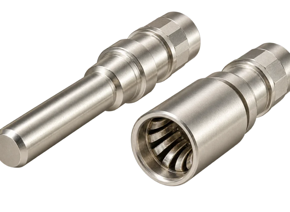
전기차 급속충전 커넥터 접점: 고전류를 받는 핀과 소켓의 구조
전기차 급속충전 커넥터 접점은 차량 인렛의 핀과 충전 플러그의 소켓이 만드는 고전류 인터페이스입니다. 눈에 잘 보이지 않는 접촉대, 도금과 케이블…
ID
18 10월 2026
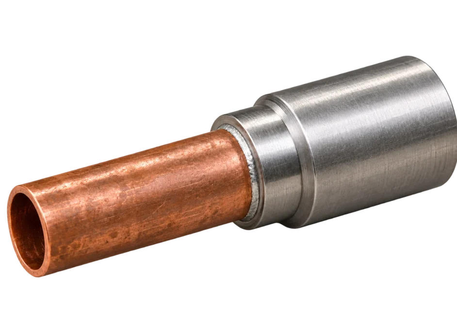
구리–스테인리스 이종 브레이징: 젖음·열간 간극·계면 내구성
구리–스테인리스 이종 브레이징 설계에서는 젖음, 열간 간극, 용가재와 공정 관리를 함께 검토해야 합니다.
ID
15 10월 2026

판금 루버 성형: 개구 형상·금형·압력손실을 연결하는 설계
루버는 판에 구멍을 많이 만드는 작업을 넘어, 절개한 재료를 원하는 방향으로 세워 공기의 통로와 패널의 구조를 함께 만드는 성형입니다.
ID
13 10월 2026
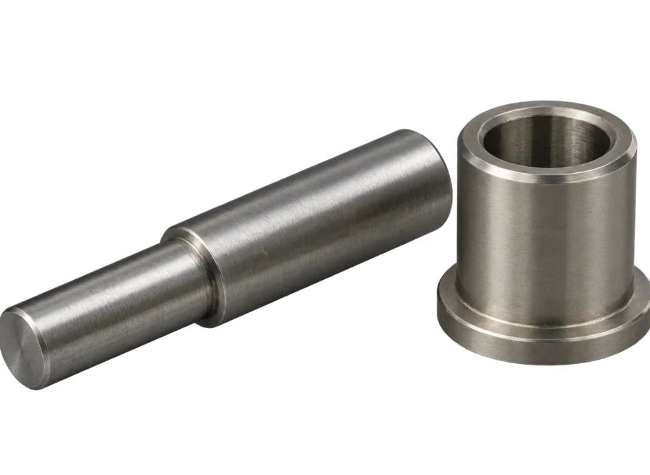
도금 공차 설계: 기능 치수·두께 분포·완성 검사
정밀 부품의 표면처리는 재료의 기능을 바꾸면서 조립 공간도 바꿉니다. 외경은 커지고 내경은 작아지며, 마스킹 경계와 국부 성장까지 상대 부품의 움직임에…
 ID
12 10월 2026

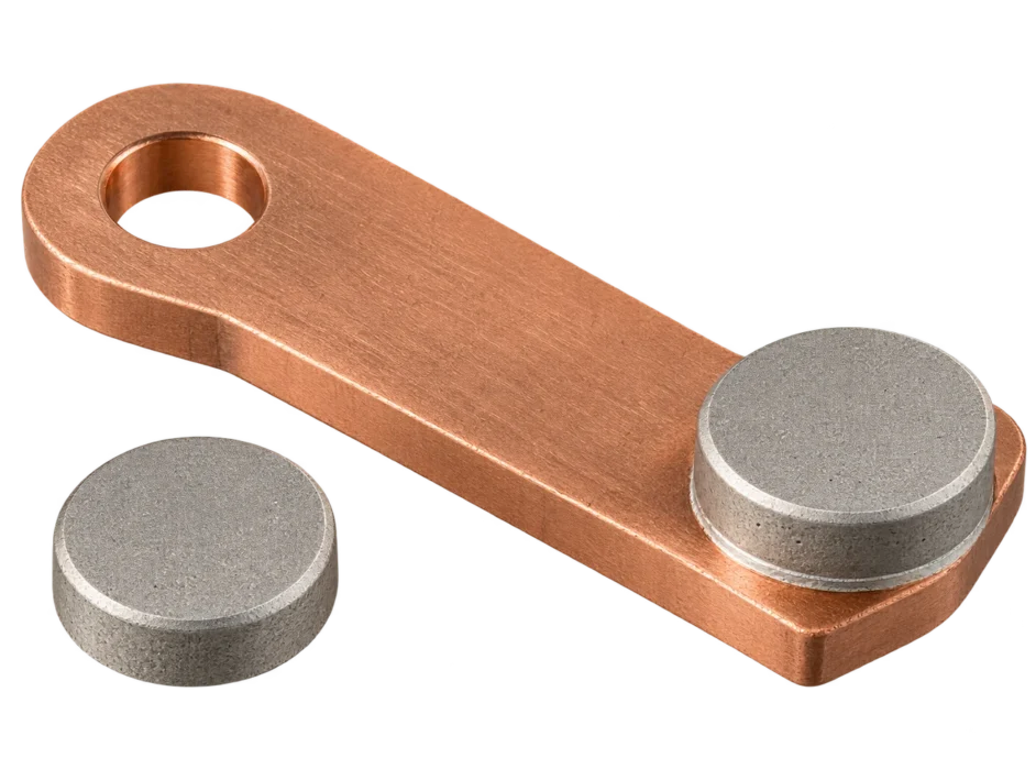
리벳 접점 조립품: 프레스 스프링·와이퍼 브러시의 설계와 품질관리
프레스 스프링과 와이퍼 브러시를 구성하는 리벳 접점 조립품의 구조·소재·리베팅 공정을 살펴보고, 접촉력·저항·마모를 연결해 설계와 품질관리의 핵심을 정리합니다.
