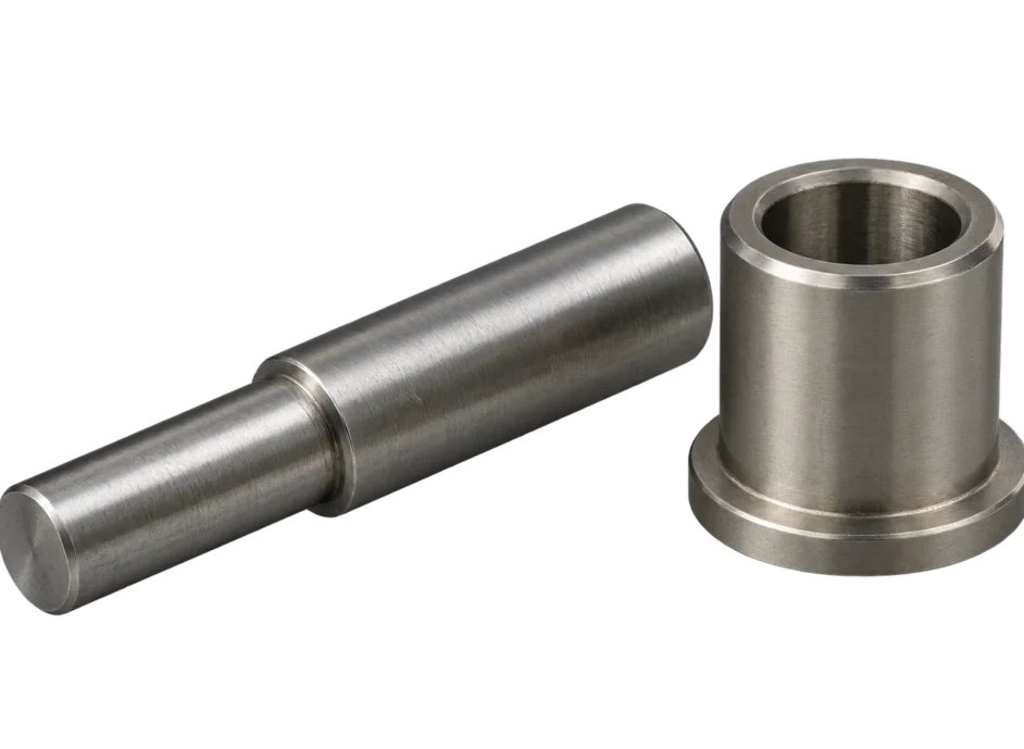
PRECISION SLEEVES / 숄더·플랜지와 관통 내경

STAINLESS SLEEVE ENGINEERING

정밀하게 맞추고,
오래 유지하다.

SUS316L 슬리브의 맞춤·형상·갈링·표면 품질

PRECISION SLEEVES / 숄더·플랜지와 관통 내경

Align.
Fit.
Endure.

STAINLESS SLEEVE ENGINEERING

PRECISION SLEEVES / 숄더·플랜지와 관통 내경

하나의 슬리브,
세 면의 정밀도.

내경·외경·끝면과 상대품의 관계에서 슬리브의 제작·검증 기준을 살펴봅니다.

정렬 · 맞춤 · 표면 · 검증

Overview.

정밀한 맞춤은, 조립 후에도 유지되어야 합니다.

정밀 슬리브의 신뢰성은 재질의 내식성과 내경·외경·끝면의 관계를 함께 관리할 때 높아집니다. 상온 치수가 맞아도 압입 변형과 열팽창, 표면 응착과 세척 잔류물이 최종 조립 기능을 바꿀 수 있습니다.

아이디솔루텍은 SUS316L 슬리브를 상대 축과 하우징이 만나는 정밀 인터페이스로 검토합니다. 재료 상태, 갈링 기구, 적용 규격과 계측 조건을 연결하여 제작부터 장착 후 검증까지 살펴봅니다.

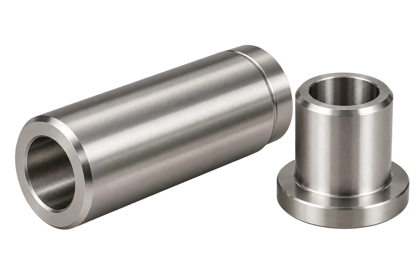
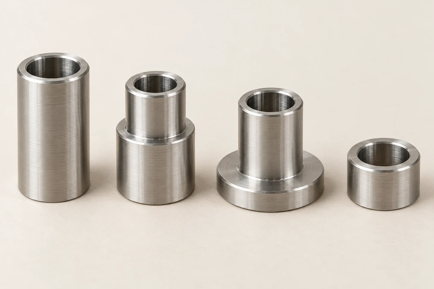
SLEEVE FAMILY / 직관·단차·플랜지·스페이서 구조

SLEEVE FAMILY / 직관·단차·플랜지·스페이서 구조

Structure.

슬리브 기능과 조립 형상

01 / FUNCTIONAL SLEEVE

슬리브의 역할을 먼저 구분하다

같은 원통형 부품도 하중과 상대 운동은 다릅니다.

정밀 슬리브는 축을 안내하거나 하우징 안에서 위치를 유지하고, 체결 간격을 정하거나 마모면을 분리하는 데 사용됩니다. 부품 이름보다 내경·외경·끝면 중 어느 면이 기능을 결정하는지 먼저 확인합니다.

정지 상태의 위치 결정 슬리브와 연속 회전하는 미끄럼 베어링은 요구가 다릅니다. SUS316L이라는 재질명만으로 무윤활 회전이나 특정 하중·속도에서의 수명을 보증할 수 없습니다.

첫 번째 3D에서는 하우징, 플랜지 슬리브와 상대 축을 분해·삽입·장착·단면 순서로 확인합니다. 내측 축과 외측 하우징의 맞춤은 각각 정해야 하며, 표시된 간극은 실제 공차값이 아닙니다.

축 안내

내경과 상대 운동 · 하중·속도·윤활 조건

하우징 고정

외경과 접촉 길이 · 끼워맞춤·유지 방식

축방향 기준

끝면·플랜지 · 누적 길이와 지지 상태

슬리브의 역할을 먼저 구분하다 — 실무 판단 기준

검토 항목기술적 의미검증·관리 기준
축 안내내경과 상대 운동하중·속도·윤활 조건
하우징 고정외경과 접촉 길이끼워맞춤·유지 방식
축방향 기준끝면·플랜지누적 길이와 지지 상태

축 안내

기술적 의미
내경과 상대 운동

검증·관리 기준
하중·속도·윤활 조건

하우징 고정

기술적 의미
외경과 접촉 길이

검증·관리 기준
끼워맞춤·유지 방식

축방향 기준

기술적 의미
끝면·플랜지

검증·관리 기준
누적 길이와 지지 상태

02 / GEOMETRY & LOAD PATH

내경·외경·끝면을 하나의 구조로 보다

직경만 맞아도 조립 축선은 어긋날 수 있습니다.

외경은 하우징과의 위치를, 내경은 상대 축과의 관계를, 끝면은 축방향 안착을 결정합니다. 두 직경이 각각 치수 공차 안에 있어도 축선 관계와 끝면 방향이 맞지 않으면 편심·기울기·국부 접촉이 생깁니다.

플랜지는 축방향 정지와 하중 분산에 유리할 수 있지만, 어깨의 모서리와 상대품 필렛이 간섭하면 기준면이 완전히 닿지 않습니다. 릴리프, 모따기와 접촉 폭을 단면에서 함께 검토합니다.

도면에는 기능 기준과 필요한 형상·방향·위치 요구를 구체적으로 지정합니다. 공차 체계가 다른 도면의 기호를 임의로 바꾸거나, 동심이라는 일반 표현만으로 검사 방법까지 정해졌다고 간주하지 않습니다.

내·외경 관계

정렬과 편심 · 기능 기준 축 설정

끝면 관계

축방향 안착 · 직각·흔들림 요구 구분

어깨 모서리

필렛·릴리프 간섭 · 실제 접촉 폭 확인

도면의 축선 관계 요구를 단순한 내외경 크기 차이로 대체할 수 없습니다.

측정 상태의 명시

기준 축선과 끝면을 지정할 때 자유 상태, 장착 상태와 클램프 조건을 함께 정의해 형상 평가의 경계를 고정합니다.

내경·외경·끝면을 하나의 구조로 보다 — 실무 판단 기준

검토 항목기술적 의미검증·관리 기준
내·외경 관계정렬과 편심기능 기준 축 설정
끝면 관계축방향 안착직각·흔들림 요구 구분
어깨 모서리필렛·릴리프 간섭실제 접촉 폭 확인

내·외경 관계

기술적 의미
정렬과 편심

검증·관리 기준
기능 기준 축 설정

끝면 관계

기술적 의미
축방향 안착

검증·관리 기준
직각·흔들림 요구 구분

어깨 모서리

기술적 의미
필렛·릴리프 간섭

검증·관리 기준
실제 접촉 폭 확인

Materials.

재질 상태와 부식 환경

03 / MATERIAL CONDITION

316L의 장점과 한계를 함께 설계하다

저탄소·몰리브덴 합금의 목적을 사용 환경과 연결합니다.

316L 계열은 몰리브덴을 포함하는 오스테나이트계 스테인리스강이며 낮은 탄소량은 열이력 후 입계부식 민감도를 줄이는 데 도움이 됩니다. 그러나 L 표기는 높은 경도나 갈링 저항을 의미하지 않습니다.

SUS316L, EN 1.4404와 UNS S31603은 대응을 검토할 수 있는 표기이지만 발주 규격·제품 형태·성적서까지 자동으로 같아지는 것은 아닙니다. 봉재에서 절삭한 부품에는 해당 봉재 상태와 공급 규격을 확인합니다.

냉간가공 상태, 잔류응력과 경도는 가공 변형과 조립 거동에 영향을 줍니다. 용체화나 추가 열처리가 필요하면 치수·표면·세척 계획을 함께 다시 검토하고 재질명만으로 공정을 생략하지 않습니다.

재료 표기

규격·제품 형태 차이 · 발주와 성적서 확인

저탄소 설계

열이력 후 부식 민감도 · 실제 사용 조건 검토

공급 상태

경도·잔류응력 · 가공·조립 영향 확인

공급 상태 확인

발주에는 합금 표기와 함께 제품 형태, 공급 상태 및 필요한 성적서 항목을 적고 재료 대체 승인 경로를 정합니다.

316L의 장점과 한계를 함께 설계하다 — 실무 판단 기준

검토 항목기술적 의미검증·관리 기준
재료 표기규격·제품 형태 차이발주와 성적서 확인
저탄소 설계열이력 후 부식 민감도실제 사용 조건 검토
공급 상태경도·잔류응력가공·조립 영향 확인
열처리치수와 표면 변화후속 검사·세척 계획

재료 표기

기술적 의미
규격·제품 형태 차이

검증·관리 기준
발주와 성적서 확인

저탄소 설계

기술적 의미
열이력 후 부식 민감도

검증·관리 기준
실제 사용 조건 검토

공급 상태

기술적 의미
경도·잔류응력

검증·관리 기준
가공·조립 영향 확인

열처리

기술적 의미
치수와 표면 변화

검증·관리 기준
후속 검사·세척 계획

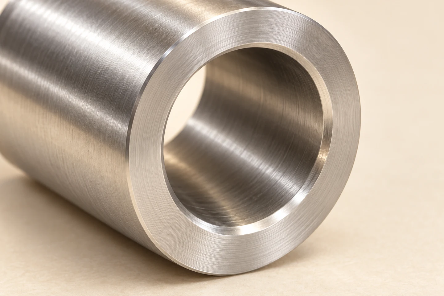
BORE & END FACE / 입구 모따기·내경·정밀 끝면

BORE & END FACE / 입구 모따기·내경·정밀 끝면

04 / CORROSION INTERFACE

틈새와 세정 잔류물까지 검토하다

316L도 염화물과 정체된 틈새에서 조건을 탑니다.

슬리브 외경과 하우징의 좁은 틈, 플랜지 아래와 씰 뒤쪽은 외부에서 잘 보이지 않는 정체 공간이 될 수 있습니다. 염화물 농도, 온도, pH와 젖음·건조 반복을 재질 선정 입력으로 정리합니다.

모든 틈을 단순히 좁히는 방법이 내식성을 보장하지는 않습니다. 기능상 필요한 맞춤과 씰 구조를 유지하면서 배수·세척 가능성과 오염 축적 경로를 검토하고, 실제 조립 상태에서 환경 시험을 계획합니다.

다른 금속 하우징을 사용할 때는 전해질 존재와 전기적 접촉, 면적 비도 고려합니다. 표면이 깨끗하다는 육안 판단만으로 잔류 이온이나 얇은 유막이 없다고 결론내리지 않습니다.

외부 표면이 깨끗해도 좁은 내경과 겹침부의 잔류 상태는 다를 수 있습니다.

틈새와 세정 잔류물까지 검토하다 — 실무 판단 기준

검토 항목기술적 의미검증·관리 기준
환경 입력염화물·온도·pH최악 사용·세정 조건
틈새 형상플랜지·씰·맞춤부배수·세척 접근성
이종 금속전해질·면적 비접촉·절연 설계 검토
검증 시료완성 조립체오염·정체 조건 반영

환경 입력

기술적 의미
염화물·온도·pH

검증·관리 기준
최악 사용·세정 조건

틈새 형상

기술적 의미
플랜지·씰·맞춤부

검증·관리 기준
배수·세척 접근성

이종 금속

기술적 의미
전해질·면적 비

검증·관리 기준
접촉·절연 설계 검토

검증 시료

기술적 의미
완성 조립체

검증·관리 기준
오염·정체 조건 반영

3D · 슬리브·하우징·축의 동심 조립

STRUCTURE & INTERFACE
ID SOLUTECH / 01
인터랙티브 3D를 준비하고 있습니다.
장착

슬리브의 축방향 위치와 상대 축을 확인합니다. 간극은 표시를 위해 확대되었습니다.

드래그·방향키: 회전 / + −: 확대·축소 / Home: 초기화슬리브·하우징·축의 동심 조립

직경이 맞아도 축선과 끝면은 따로 확인해야 합니다.

Precision.

가공 변형과 표면 측정

05 / MACHINING STRATEGY

얇은 벽의 변형을 공정 순서로 줄이다

척에서의 치수와 해제 후의 치수를 구분합니다.

슬리브는 중공 형상 때문에 같은 외경의 실축보다 클램프와 절삭 하중에 민감할 수 있습니다. 척 죠의 접촉 폭, 파지 길이, 과도한 물림 압력이 내경과 원형도에 미치는 영향을 확인합니다.

황삭과 정삭 사이의 여유, 반전 가공에서의 기준 이전, 칩 배출과 공구 마모를 함께 관리합니다. 가공 경화가 있는 재료에서 마찰만 반복되는 절삭 상태를 방치하면 표면과 치수 반복성이 나빠질 수 있습니다.

완성 치수는 파지 해제와 온도 안정화 후 확인하고 필요한 경우 실제 장착 상태에서도 다시 측정합니다. 자유 상태 검사와 조립 상태 검사를 구분해 기록해야 변형의 발생 위치를 찾을 수 있습니다.

파지

죠 폭·길이·압력 · 해제 전후 변형 비교

공정 순서

황삭·정삭·반전 · 기준 이전과 여유 관리

절삭 상태

마모·칩·마찰 · 표면·치수 추세 관찰

클램프 해제 후 확인

얇은 벽은 공정 중 치수와 클램프 해제 뒤 치수를 비교해 지지 압력과 가공 순서가 결과에 미치는 영향을 확인합니다.

얇은 벽의 변형을 공정 순서로 줄이다 — 실무 판단 기준

검토 항목기술적 의미검증·관리 기준
파지죠 폭·길이·압력해제 전후 변형 비교
공정 순서황삭·정삭·반전기준 이전과 여유 관리
절삭 상태마모·칩·마찰표면·치수 추세 관찰
최종 상태자유·조립·온도측정 조건 구분 기록

파지

기술적 의미
죠 폭·길이·압력

검증·관리 기준
해제 전후 변형 비교

공정 순서

기술적 의미
황삭·정삭·반전

검증·관리 기준
기준 이전과 여유 관리

절삭 상태

기술적 의미
마모·칩·마찰

검증·관리 기준
표면·치수 추세 관찰

최종 상태

기술적 의미
자유·조립·온도

검증·관리 기준
측정 조건 구분 기록

06 / FORM & TEXTURE

직경·형상·거칠기를 따로 확인하다

하나의 Ra나 두 점 직경으로 기능을 다 설명할 수 없습니다.

직경은 크기를 나타내며 원형도와 원통도는 형상에 관한 정보입니다. 내경의 한 단면에서 두 점을 잰 결과만으로 길이 방향 테이퍼·배럴 형상·로빙을 모두 검출했다고 판단하지 않습니다.

표면 거칠기는 측정 방향과 필터·컷오프에 영향을 받습니다. 상대 운동이나 씰 접촉이 있는 면은 평균 거칠기뿐 아니라 가공 방향, 피크와 골, 국부 흠집의 기능 영향을 함께 봅니다.

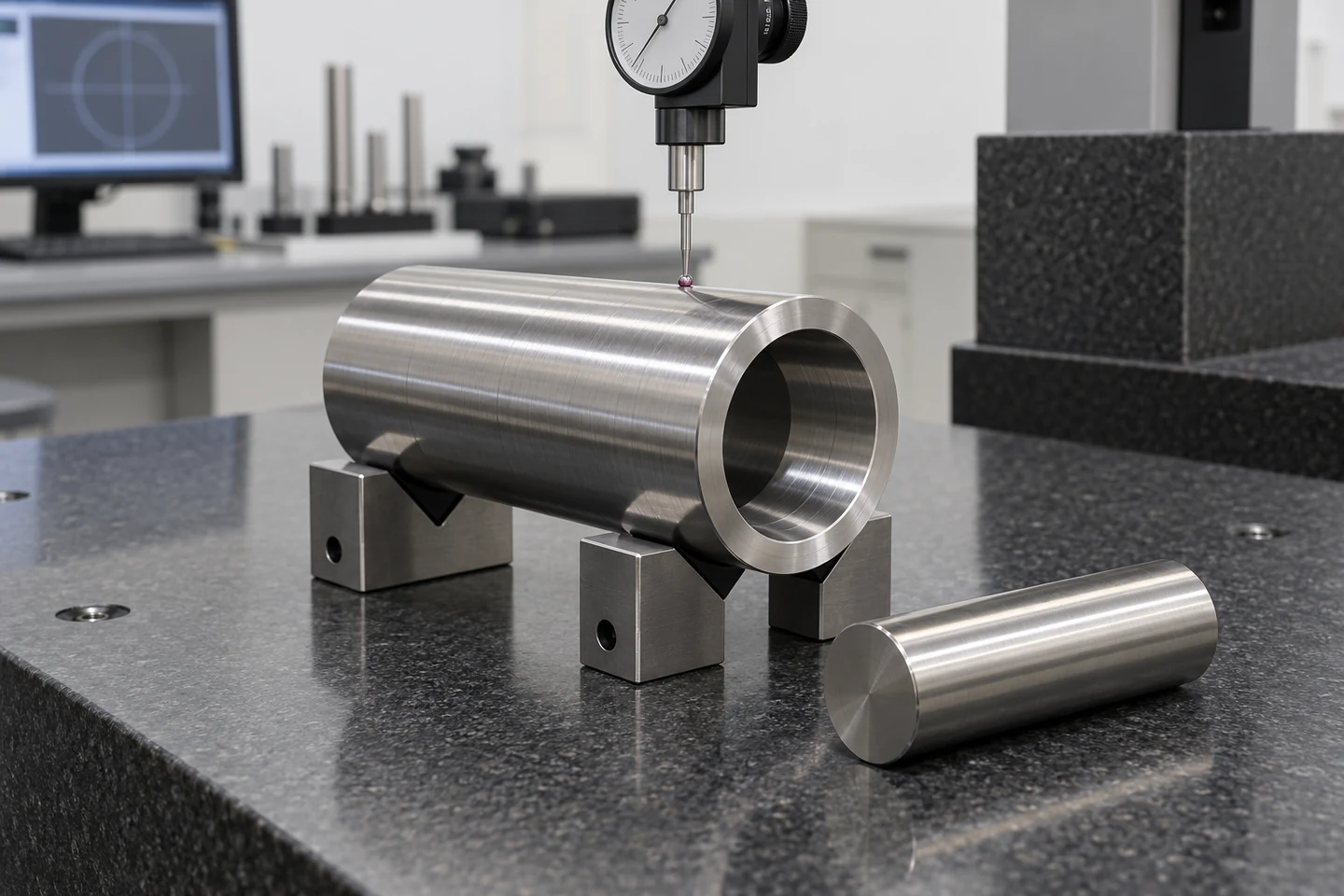
두 번째 3D는 회전 기준 치구에서 외경·내경·끝면에 접근하는 순서를 보여줍니다. 사진의 V블록 지지는 별도의 간이 점검 구성으로, 그 지시값을 정밀 원형도 측정 결과와 동일시하지 않습니다.

치수

내·외경과 길이 · 단면·방향·온도 지정

형상

원형·원통·끝면 · 목적에 맞는 장비·전략

거칠기

방향·필터·파라미터 · 기능과 측정 조건 연결

측정 항목 분리

크기·원형도·원통도·끝면 관계와 표면 거칠기의 요구를 나눠 필요한 접근 범위와 검사 방법을 각각 정합니다.

직경·형상·거칠기를 따로 확인하다 — 실무 판단 기준

검토 항목기술적 의미검증·관리 기준
치수내·외경과 길이단면·방향·온도 지정
형상원형·원통·끝면목적에 맞는 장비·전략
거칠기방향·필터·파라미터기능과 측정 조건 연결
국부 결함버·찍힘·스크래치사용면 기준 판정

치수

기술적 의미
내·외경과 길이

검증·관리 기준
단면·방향·온도 지정

형상

기술적 의미
원형·원통·끝면

검증·관리 기준
목적에 맞는 장비·전략

거칠기

기술적 의미
방향·필터·파라미터

검증·관리 기준
기능과 측정 조건 연결

국부 결함

기술적 의미
버·찍힘·스크래치

검증·관리 기준
사용면 기준 판정

COMPARATIVE INSPECTION / V블록 지지와 외주면 프로브 접근

COMPARATIVE INSPECTION / V블록 지지와 외주면 프로브 접근

Motion.

삽입·갈링·열팽창

07 / ASSEMBLY & GALLING

압입력과 갈링을 함께 관리하다

큰 힘은 정렬 불량을 해결하는 기준이 아닙니다.

간섭 맞춤에서는 접촉압과 마찰이 유지력에 기여하지만 압입 중 표면 손상과 내경 수축도 생길 수 있습니다. 얇은 슬리브는 외측 간섭이 내측 축의 간극까지 바꾸므로 조립 후 기능 치수를 확인합니다.

스테인리스 접촉면의 갈링은 단순한 긁힘을 넘어 응착과 재료 이동이 동반되는 손상입니다. 304L·316L 접촉에서도 응착 전이가 발생할 수 있으므로 상대 재질과 표면 상태를 함께 평가합니다.

입구 모따기, 축 정렬, 삽입 속도와 승인된 윤활 조건을 관리하고 힘–변위 곡선의 급격한 변화와 표면 흔적을 연결합니다. 윤활제를 추가하면 마찰·유지력·청정도 조건도 달라지므로 조립 편의만으로 변경하지 않습니다.

맞춤 설계

간섭·벽 두께·길이 · 조립 후 내경 확인

삽입 경로

정렬·모따기·속도 · 과도한 힘 보정 방지

갈링 관리

응착·전이·표면막 · 상대 재질과 윤활 검토

힘이 낮아졌다는 결과만으로 갈링이 제거되거나 유지력이 확보되었다고 판단하지 않습니다.

삽입 이상 위치 기록

힘–변위 기록에서 이상이 시작된 위치를 표면 손상 위치와 대조하고 조립 방향·윤활·정렬 이력을 함께 보존합니다.

압입력과 갈링을 함께 관리하다 — 실무 판단 기준

검토 항목기술적 의미검증·관리 기준
맞춤 설계간섭·벽 두께·길이조립 후 내경 확인
삽입 경로정렬·모따기·속도과도한 힘 보정 방지
갈링 관리응착·전이·표면막상대 재질과 윤활 검토
공정 감시힘–변위·표면 흔적정상 창과 이상 반응 설정

맞춤 설계

기술적 의미
간섭·벽 두께·길이

검증·관리 기준
조립 후 내경 확인

삽입 경로

기술적 의미
정렬·모따기·속도

검증·관리 기준
과도한 힘 보정 방지

갈링 관리

기술적 의미
응착·전이·표면막

검증·관리 기준
상대 재질과 윤활 검토

공정 감시

기술적 의미
힘–변위·표면 흔적

검증·관리 기준
정상 창과 이상 반응 설정

3D · 슬리브의 내경·외경·끝면 측정

PROCESS & VALIDATION
ID SOLUTECH / 02
인터랙티브 3D를 준비하고 있습니다.
내경 접근

보어 탐침이 내경에 접근합니다. 측정 온도·접촉력·설비 능력을 함께 관리합니다.

드래그·방향키: 회전 / + −: 확대·축소 / Home: 초기화슬리브의 내경·외경·끝면 측정
08 / THERMAL FIT

온도 변화 뒤의 맞춤을 계산하다

슬리브와 하우징은 같은 비율로 팽창하지 않을 수 있습니다.

상온에서 적절한 간섭이 있어도 고온에서 하우징이 더 크게 팽창하면 유지 여유가 줄어들 수 있습니다. 반대로 내측 축과 슬리브의 온도 차이는 작동 간극을 줄여 접촉과 마찰을 증가시킬 수 있습니다.

아래 식은 자유 열팽창 상태에서 슬리브 외경과 하우징 내경의 차이를 비교하는 1차 검토입니다. 온도별 팽창계수와 실제 부품 온도를 사용하고, 간섭에 따른 탄성 변형·소성 변형과 접촉압은 별도 해석합니다.

냉각된 슬리브를 따뜻한 하우징에 넣는 열조립에서는 온도 평형까지의 시간을 고려합니다. 조립 직후 쉽게 움직였다는 사실과 안정화 후 유지 성능은 다르므로 최종 검사 시점을 정의합니다.

δ(T) ≈ Dₛ₀(1 + αₛΔTₛ) − Dₕ₀(1 + αₕΔTₕ)

열팽창에 따른 직경 차이
Dₛ₀는 기준 온도의 슬리브 외경, Dₕ₀는 하우징 내경, α는 선팽창계수, ΔT는 각 부품의 기준 대비 온도 변화입니다. δ가 양수면 자유 치수 기준의 간섭, 음수면 틈새입니다. 작은 변형·구간 평균 α를 쓰는 1차 식이며 실제 접촉압·유지력 계산을 대신하지 않습니다.

부품별 온도 입력

슬리브와 하우징이 같은 온도에 도달하는지 먼저 확인하고 기동·정지·국부 가열 상황을 별도 계산 조건으로 둡니다.

온도 변화 뒤의 맞춤을 계산하다 — 실무 판단 기준

검토 항목기술적 의미검증·관리 기준
기준 치수슬리브 OD·하우징 ID동일 기준 온도
재료 팽창서로 다른 α해당 온도 구간 자료
온도 분포축·슬리브·하우징실제 운전·조립 상태
최종 검증평형 후 간극·유지변형 해석과 시험 연결

기준 치수

기술적 의미
슬리브 OD·하우징 ID

검증·관리 기준
동일 기준 온도

재료 팽창

기술적 의미
서로 다른 α

검증·관리 기준
해당 온도 구간 자료

온도 분포

기술적 의미
축·슬리브·하우징

검증·관리 기준
실제 운전·조립 상태

최종 검증

기술적 의미
평형 후 간극·유지

검증·관리 기준
변형 해석과 시험 연결

압입 전의 치수가 조립 후에도 같다는 보장은 없습니다.

Interface.

세척과 접촉면 검증

09 / CLEAN & PASSIVATE

세척과 부동태화를 순서대로 설계하다

유분·입자·철 오염은 서로 다른 제거 과제입니다.

절삭유와 칩, 연마재와 외부 철 오염은 슬리브의 좁은 내경과 단차에 남을 수 있습니다. 세척 공정은 입자·유막 제거와 배액·헹굼·건조를 포함해 형상에 맞춰 검증합니다.

ASTM A380은 세척·스케일 제거·부동태화의 구분을, A967은 화학적 부동태화와 효과 확인을 다룹니다. 부동태화가 깊은 흠집을 메우거나 잘못된 재질·표면 형상을 수정하는 작업은 아닙니다.

처리 후에는 합의된 검증 시험과 외관, 잔류물·치수 영향을 확인합니다. A967에 여러 시험이 소개되어 있다는 사실을 모든 시험을 무조건 시행해야 한다는 뜻으로 읽지 않고, 적용 규격 개정과 발주 요구에 맞는 절차를 정합니다.

부동태화 완료 표시는 보관·운송 중 재오염까지 자동으로 방지하지 않습니다.

세척 효과의 유지

처리 후 내부 배액과 건조를 확인하고 검사 치구·장갑·포장재가 다시 유분이나 입자를 옮기지 않는지 점검합니다.

세척과 부동태화를 순서대로 설계하다 — 실무 판단 기준

검토 항목기술적 의미검증·관리 기준
전처리유분·입자 제거내경·단차 잔류 확인
화학 처리재질·오염별 조건승인 절차 적용
헹굼·건조용액 잔류와 정체배액과 재오염 방지
효과 확인합의 시험·외관규격 개정과 판정 기록

전처리

기술적 의미
유분·입자 제거

검증·관리 기준
내경·단차 잔류 확인

화학 처리

기술적 의미
재질·오염별 조건

검증·관리 기준
승인 절차 적용

헹굼·건조

기술적 의미
용액 잔류와 정체

검증·관리 기준
배액과 재오염 방지

효과 확인

기술적 의미
합의 시험·외관

검증·관리 기준
규격 개정과 판정 기록

10 / SURFACE VALIDATION

시험편의 갈링 결과를 실제 조립과 구분하다

손상 기구를 분석하고 조립체 시험으로 실제 적용성을 확인합니다.

316L의 산화·표면막 상태는 미끄럼 접촉의 갈링 손상에 영향을 줄 수 있습니다. 수환경 노출 이력과 표면 상태를 함께 평가하되, 이를 근거로 일반 슬리브에 임의 산화처리를 적용하지 않습니다.

실제 부품의 접촉압, 미끄럼 길이, 속도와 윤활 상태는 평가용 시험편과 다를 수 있습니다. 고객 조립 조건을 재현한 삽입·분해·반복 사용 시험을 별도로 설계하고 재조립 허용 여부도 정합니다.

손상 분석에는 위치·방향·재료 이동 흔적과 힘 기록을 함께 남깁니다. 현미경 관찰이나 성분 분석이 필요하면 단순 치수 불량과 응착 마모, 이물 끼임을 구분할 수 있는 시료 상태를 보존합니다.

시험 조건 해석

시험편·환경의 범위 · 조건 밖 수치 전용 금지

제품 시험

실제 접촉·조립 조건 · 삽입·분해·재사용 구분

손상 기록

위치·방향·재료 전이 · 힘 기록과 연결

시험 조건의 대응표

평가 시험과 제품의 재질·하중·운동·윤활 조건을 나란히 적어 직접 비교 가능한 항목과 추가 검증 항목을 구분합니다.

시험편의 갈링 결과를 실제 조립과 구분하다 — 실무 판단 기준

검토 항목기술적 의미검증·관리 기준
시험 조건 해석시험편·환경의 범위조건 밖 수치 전용 금지
제품 시험실제 접촉·조립 조건삽입·분해·재사용 구분
손상 기록위치·방향·재료 전이힘 기록과 연결
원인 분석형상·갈링·이물시료와 이력 보존

시험 조건 해석

기술적 의미
시험편·환경의 범위

검증·관리 기준
조건 밖 수치 전용 금지

제품 시험

기술적 의미
실제 접촉·조립 조건

검증·관리 기준
삽입·분해·재사용 구분

손상 기록

기술적 의미
위치·방향·재료 전이

검증·관리 기준
힘 기록과 연결

원인 분석

기술적 의미
형상·갈링·이물

검증·관리 기준
시료와 이력 보존

Validation.

검사 체계와 양산 승인

11 / INSPECTION & TRACEABILITY

검사 체계를 기능면별로 구성하다

한 장의 치수표에 조립 상태와 측정 조건을 남깁니다.

입고 재료와 가공 로트, 공구·세척·부동태화 이력을 연결하고 기능 치수를 검사합니다. 플러그 게이지는 특정 크기 한계의 판정에 유용할 수 있지만 형상 전체와 축선 관계는 별도 방법으로 확인해야 합니다.

얇은 벽을 측정할 때는 측정력과 지지 조건을 관리합니다. 내경 게이지·에어 게이지·형상 측정기 등은 접근 범위와 검출 가능한 결함이 다르므로 실제 도면 요구와 측정시스템 능력을 기준으로 조합합니다.

온도 안정화, 영점 확인, 기준 시편과 재측정 절차를 작업 지침에 넣습니다. 검사자나 설비를 바꿨을 때의 차이를 확인해 제조 변동과 측정 변동을 혼동하지 않게 합니다.

재료·공정

heat·가공·표면처리 · 로트 추적 유지

크기 판정

게이지·측정 범위 · 한계와 검출 범위 명시

형상 평가

축선·원통·끝면 · 기능별 전략 설정

측정값을 맞추기 위해 지지 조건을 바꾸면 실제 형상 변화와 검사 변화를 구분하기 어려워집니다.

재측정 절차의 통일

내경 이상이 발견되면 청정도·온도·영점·지지를 같은 순서로 확인하고 재측정 결과와 초기 결과를 함께 보관합니다.

검사 체계를 기능면별로 구성하다 — 실무 판단 기준

검토 항목기술적 의미검증·관리 기준
재료·공정heat·가공·표면처리로트 추적 유지
크기 판정게이지·측정 범위한계와 검출 범위 명시
형상 평가축선·원통·끝면기능별 전략 설정
측정 신뢰성온도·힘·기준 시편반복성·재현성 확인

재료·공정

기술적 의미
heat·가공·표면처리

검증·관리 기준
로트 추적 유지

크기 판정

기술적 의미
게이지·측정 범위

검증·관리 기준
한계와 검출 범위 명시

형상 평가

기술적 의미
축선·원통·끝면

검증·관리 기준
기능별 전략 설정

측정 신뢰성

기술적 의미
온도·힘·기준 시편

검증·관리 기준
반복성·재현성 확인

12 / DESIGN RELEASE

상대품까지 포함해 슬리브를 승인하다

내식성과 체결성은 최종 조립에서 만납니다.

아이디솔루텍의 정밀 슬리브 검토는 내경·외경·끝면의 관계와 상대 재질, 조립·사용 온도에서 출발합니다. 재질 선택, 가공 순서, 표면 청정도와 장착 후 치수를 하나의 제작 계획으로 연결합니다.

초도품에서는 자유 상태 치수와 조립 후 기능을 함께 확인하고, 양산에서는 공구 마모·세척 변화·압입 힘 추세를 감시합니다. 치수만 보정하며 갈링이나 오염 원인을 남겨두지 않도록 이상 반응을 명확히 합니다.

검토 요청에는 슬리브와 하우징·축 도면, 맞춤 의도, 하중·상대 운동·윤활, 유체와 세정 환경, 수량·일정을 전달합니다. 합의된 검사 기준과 시험 범위가 정밀 체결의 재현성을 만듭니다.

설계 입력

상대품·맞춤·환경 · 기능 기준과 위험 확인

제작 계획

재료·가공·세척 · 순서와 검사 상태 정의

초도 검증

자유·조립 상태 · 치수·유지·손상 연결

장착 후 승인 조건

초도 조립 결과에 슬리브·축·하우징 식별과 조립 조건을 남기고 재사용 또는 교체 기준을 필요 범위에서 합의합니다.

상대품까지 포함해 슬리브를 승인하다 — 실무 판단 기준

검토 항목기술적 의미검증·관리 기준
설계 입력상대품·맞춤·환경기능 기준과 위험 확인
제작 계획재료·가공·세척순서와 검사 상태 정의
초도 검증자유·조립 상태치수·유지·손상 연결
양산 관리마모·오염·힘 추세변경과 재검증 기록

설계 입력

기술적 의미
상대품·맞춤·환경

검증·관리 기준
기능 기준과 위험 확인

제작 계획

기술적 의미
재료·가공·세척

검증·관리 기준
순서와 검사 상태 정의

초도 검증

기술적 의미
자유·조립 상태

검증·관리 기준
치수·유지·손상 연결

양산 관리

기술적 의미
마모·오염·힘 추세

검증·관리 기준
변경과 재검증 기록

내식성은 재질과 형상, 세척 상태가 함께 만듭니다.

Start a
Project.

슬리브·축·하우징 도면과 맞춤 의도, 하중·운동·온도·유체·윤활 조건, 재료·표면·검사 요구를 보내주세요. 조립 후 기능과 수량·일정에 맞춰 제작 범위를 검토합니다.

Provide sleeve, shaft and housing drawings, intended fits, load, motion, temperature, media, lubrication and material, surface and inspection requirements. Review manufacturing scope around installed function, quantity and timing.

개발 상담 · Contact

기술 협의 · Engineering Consultation
도면과 사양을 기준으로 소재·가공·표면처리,
주요 품질 항목과 공급 조건을 함께 검토합니다.


We review drawings and specifications to define materials, manufacturing methods, surface finishes, key quality requirements, and supply conditions.

개발 의뢰하기 · Development Inquiry

    도면 및 기술자료
    Drawings & Technical Documents

    도면 번호와 개정 이력이 표시된 2D·3D 도면을 첨부해 주세요.
    사양서와 검사 기준도 함께 전달할 수 있습니다.
    Attach your 2D or 3D drawings with their drawing numbers and revisions.
    Include specifications and inspection criteria as needed.

    파일을 이곳에 놓아주세요Drag & drop your files here

    선택된 파일 없음 / No files attached

    최대 5개 · 파일당 5MB · 총 15MB / Up to 5 files · 5MB each · 15MB total
    PDF · DWG · DXF · STEP/STP · IGS/IGES · JPG · PNG · ZIP

    * 필수 입력 / Required fields

    STAINLESS SLEEVE ENGINEERING

    PRECISION SLEEVES / 숄더·플랜지와 관통 내경

    One Sleeve.
    Three Critical Surfaces.

    Explore manufacturing and verification through the bore, outside diameter, end face and their mating components.

    ALIGN · FIT · FINISH · VERIFY

    ENGLISH EDITION

    Fit with Precision.
    Retain the Function.

    Fits, form, galling and surface quality in 316L sleeves

    A precise fit must remain functional after assembly.

    Precision-sleeve reliability depends on both corrosion behavior and the relationship between bore, outside diameter and end face. Correct room-temperature dimensions can still change function through installation distortion, thermal expansion, adhesion or cleaning residues.

    ID SOLUTECH treats a 316L sleeve as the precision interface between shaft and housing. Connect material condition, galling mechanisms, applicable standards and metrology with manufacturing decisions and verification after installation.

    SLEEVE FAMILY / 직관·단차·플랜지·스페이서 구조

    SLEEVE FAMILY / Plain, stepped, flanged and spacer forms

    Structure.

    Sleeve function and assembly geometry

    01 / FUNCTIONAL SLEEVE

    Define the Sleeve Function First

    Similar cylindrical parts can carry very different loads and motion.

    A precision sleeve may guide a shaft, locate within a housing, establish a clamping distance or separate a wear surface. Identify whether the bore, outside diameter or end face controls the function before selecting a manufacturing route.

    A stationary locating sleeve and a continuously rotating plain bearing have different requirements. The designation 316L alone cannot establish dry-running capability or endurance at a particular load and speed.

    The first 3D assembly separates housing, flanged sleeve and mating shaft before insertion and section review. Define the inner and outer fits independently; the displayed clearance is not a manufacturing tolerance.

    Shaft guidance

    Bore and relative motion. Load, speed and lubrication

    Housing location

    Outside diameter and engagement. Fit and retention method

    Axial reference

    End face or flange. Stack length and support

    Define the Sleeve Function First — Review Criteria

    Review itemEngineering significanceVerification or control
    Shaft guidanceBore and relative motionLoad, speed and lubrication
    Housing locationOutside diameter and engagementFit and retention method
    Axial referenceEnd face or flangeStack length and support

    Shaft guidance

    Engineering significance
    Bore and relative motion

    Verification or control
    Load, speed and lubrication

    Housing location

    Engineering significance
    Outside diameter and engagement

    Verification or control
    Fit and retention method

    Axial reference

    Engineering significance
    End face or flange

    Verification or control
    Stack length and support

    02 / GEOMETRY & LOAD PATH

    Treat Bore, Outside Diameter and End Face as One Structure

    Correct diameters do not necessarily establish a common assembly axis.

    The outside diameter locates in the housing, the bore relates to the shaft, and the end face establishes axial seating. Separate size compliance can coexist with axis misalignment or face tilt that causes eccentricity and localized contact.

    A flange can provide an axial stop and spread load, but an incompatible shoulder corner and mating fillet may prevent full seating. Review relief, lead-in chamfers and the contact width in section.

    Specify functional references and the necessary form, orientation and location controls on the drawing. Do not translate symbols between tolerance systems casually or assume the general word concentric defines a complete inspection method.

    Bore-to-OD relationship

    Alignment and eccentricity. Define a functional reference axis

    End-face relationship

    Axial seating. Separate orientation and runout requirements

    Shoulder corner

    Fillet or relief interference. Check actual contact width

    A required axis relationship cannot be replaced by the difference between bore and outside sizes.

    Declared measurement state

    Define free, installed and clamping states with the datum axis and end face so the boundary of the geometric evaluation remains clear.

    Treat Bore, Outside Diameter and End Face as One Structure — Review Criteria

    Review itemEngineering significanceVerification or control
    Bore-to-OD relationshipAlignment and eccentricityDefine a functional reference axis
    End-face relationshipAxial seatingSeparate orientation and runout requirements
    Shoulder cornerFillet or relief interferenceCheck actual contact width

    Bore-to-OD relationship

    Engineering significance
    Alignment and eccentricity

    Verification or control
    Define a functional reference axis

    End-face relationship

    Engineering significance
    Axial seating

    Verification or control
    Separate orientation and runout requirements

    Shoulder corner

    Engineering significance
    Fillet or relief interference

    Verification or control
    Check actual contact width

    Materials.

    Material condition and corrosive exposure

    03 / MATERIAL CONDITION

    Design Around Both the Strengths and Limits of 316L

    Connect the low-carbon and molybdenum alloy design to service conditions.

    The 316L family is molybdenum-alloyed austenitic stainless steel; reduced carbon helps limit susceptibility to intergranular corrosion after thermal exposure. The L designation does not mean high hardness or resistance to galling.

    SUS316L, EN 1.4404 and UNS S31603 can be compared, but their procurement documents, product forms and certificates are not automatically interchangeable. A part machined from bar requires verification of the bar specification and supply condition.

    Cold work, residual stress and hardness influence machining distortion and assembly response. If solution treatment or another thermal operation is required, reassess dimensional, surface and cleaning controls rather than inferring a process from the grade name alone.

    Designation

    Specification and product form. Verify order and certificate

    Low-carbon design

    Post-heat corrosion susceptibility. Review actual exposure

    Supply condition

    Hardness and residual stress. Assess machining and assembly

    Supply-condition check

    Specify product form, supply condition and required certificate items alongside alloy designation, and define material-substitution approval.

    Design Around Both the Strengths and Limits of 316L — Review Criteria

    Review itemEngineering significanceVerification or control
    DesignationSpecification and product formVerify order and certificate
    Low-carbon designPost-heat corrosion susceptibilityReview actual exposure
    Supply conditionHardness and residual stressAssess machining and assembly
    Heat treatmentDimensional and surface changesPlan subsequent checks and cleaning

    Designation

    Engineering significance
    Specification and product form

    Verification or control
    Verify order and certificate

    Low-carbon design

    Engineering significance
    Post-heat corrosion susceptibility

    Verification or control
    Review actual exposure

    Supply condition

    Engineering significance
    Hardness and residual stress

    Verification or control
    Assess machining and assembly

    Heat treatment

    Engineering significance
    Dimensional and surface changes

    Verification or control
    Plan subsequent checks and cleaning

    BORE & END FACE / 입구 모따기·내경·정밀 끝면

    BORE & END FACE / Lead-in chamfer, bore and turned end face

    04 / CORROSION INTERFACE

    Review Crevices and Retained Cleaning Residues

    316L still depends on chloride exposure and crevice conditions.

    The sleeve-to-housing fit, underside of a flange and regions behind seals can form poorly visible stagnant spaces. Include chloride concentration, temperature, pH and wet–dry cycling in material selection.

    Simply narrowing every gap does not ensure corrosion resistance. Preserve the required fit and sealing function while reviewing drainage, cleanability and deposit accumulation, then plan exposure tests on the actual assembly.

    With a dissimilar-metal housing, consider electrolyte availability, electrical continuity and exposed area ratio. A visually clean surface does not prove that residual ions or thin oil films are absent.

    A clean exterior does not establish the residue condition in a narrow bore or overlap.

    Review Crevices and Retained Cleaning Residues — Review Criteria

    Review itemEngineering significanceVerification or control
    ExposureChlorides, temperature and pHWorst service and cleaning conditions
    Crevice geometryFlange, seal and fitDrainage and cleaning access
    Dissimilar metalsElectrolyte and area ratioReview bonding or isolation
    Validation sampleCompleted assemblyRepresent deposits and stagnation

    Exposure

    Engineering significance
    Chlorides, temperature and pH

    Verification or control
    Worst service and cleaning conditions

    Crevice geometry

    Engineering significance
    Flange, seal and fit

    Verification or control
    Drainage and cleaning access

    Dissimilar metals

    Engineering significance
    Electrolyte and area ratio

    Verification or control
    Review bonding or isolation

    Validation sample

    Engineering significance
    Completed assembly

    Verification or control
    Represent deposits and stagnation

    3D · Sleeve, housing and shaft alignment

    STRUCTURE & INTERFACE
    ID SOLUTECH / 01
    Preparing interactive 3D.
    Seated

    Inspect axial seating and the mating shaft. Display clearance is enlarged.

    Drag / arrow keys: rotate · + −: zoom · Home: resetSleeve, housing and shaft alignment

    Correct diameters still require verified axes and end faces.

    Precision.

    Machining distortion and surface measurement

    05 / MACHINING STRATEGY

    Control Wall Distortion through the Machining Sequence

    Distinguish restrained dimensions from the released part.

    A hollow sleeve may respond more strongly to clamping and cutting loads than a solid shaft of the same outside diameter. Evaluate jaw contact width, grip length and clamping pressure for their effect on bore size and roundness.

    Control roughing-to-finishing allowance, datum transfer during reversal, chip evacuation and tool wear together. Repeated rubbing in a work-hardening alloy can degrade both surface condition and dimensional repeatability.

    Inspect final dimensions after release and thermal stabilization, with an additional installed-state check where needed. Recording free-state and assembled-state results separately helps identify where distortion arises.

    Workholding

    Jaw width, length and pressure. Compare restrained and released form

    Operation sequence

    Roughing, finishing and reversal. Control datum transfer and stock

    Cutting condition

    Wear, chips and rubbing. Monitor surface and size trends

    Inspection after unclamping

    Compare in-process and released dimensions on thin walls to evaluate the influence of support pressure and machining sequence.

    Control Wall Distortion through the Machining Sequence — Review Criteria

    Review itemEngineering significanceVerification or control
    WorkholdingJaw width, length and pressureCompare restrained and released form
    Operation sequenceRoughing, finishing and reversalControl datum transfer and stock
    Cutting conditionWear, chips and rubbingMonitor surface and size trends
    Final conditionFree, installed and thermal stateIdentify the measurement condition

    Workholding

    Engineering significance
    Jaw width, length and pressure

    Verification or control
    Compare restrained and released form

    Operation sequence

    Engineering significance
    Roughing, finishing and reversal

    Verification or control
    Control datum transfer and stock

    Cutting condition

    Engineering significance
    Wear, chips and rubbing

    Verification or control
    Monitor surface and size trends

    Final condition

    Engineering significance
    Free, installed and thermal state

    Verification or control
    Identify the measurement condition

    06 / FORM & TEXTURE

    Inspect Size, Form and Texture Separately

    One Ra value or two-point diameter cannot describe the entire function.

    Diameter describes size, whereas roundness and cylindricity describe form. A two-point reading in one bore section does not establish the absence of taper, barrel form or lobing along the part.

    Roughness results depend on measurement direction, filtering and cutoff. For sliding or sealing surfaces, examine lay, peaks, valleys and local damage alongside the average roughness parameter.

    The second 3D view approaches the outside diameter, bore and end face on a rotational datum fixture. The photographed V-block arrangement is a separate comparative setup; its indicator movement is not automatically a precision roundness result.

    Size

    Bore, OD and length. Specify section, direction and temperature

    Form

    Roundness, cylindricity and face. Choose suitable instrument and strategy

    Texture

    Direction, filter and parameter. Link measurement to function

    Separate measurement questions

    Separate size, roundness, cylindricity, end-face relationships and texture requirements, then choose access and methods for each.

    Inspect Size, Form and Texture Separately — Review Criteria

    Review itemEngineering significanceVerification or control
    SizeBore, OD and lengthSpecify section, direction and temperature
    FormRoundness, cylindricity and faceChoose suitable instrument and strategy
    TextureDirection, filter and parameterLink measurement to function
    Local defectsBurrs, dents and scratchesJudge against the working surface

    Size

    Engineering significance
    Bore, OD and length

    Verification or control
    Specify section, direction and temperature

    Form

    Engineering significance
    Roundness, cylindricity and face

    Verification or control
    Choose suitable instrument and strategy

    Texture

    Engineering significance
    Direction, filter and parameter

    Verification or control
    Link measurement to function

    Local defects

    Engineering significance
    Burrs, dents and scratches

    Verification or control
    Judge against the working surface

    COMPARATIVE INSPECTION / V블록 지지와 외주면 프로브 접근

    COMPARATIVE INSPECTION / V-block support and outside probe access

    Motion.

    Insertion, galling and thermal expansion

    07 / ASSEMBLY & GALLING

    Control Insertion Force and Galling Together

    High force is not a remedy for poor alignment.

    Contact pressure and friction contribute to retention in an interference fit, but insertion can also damage surfaces and contract the bore. In a thin sleeve, outside interference can change the running clearance, making installed-state inspection important.

    Stainless-steel galling involves adhesion and material transfer beyond a simple scratch. When evaluating a 304L/316L mating pair, assess both material combination and surface condition rather than relying on the grade designation alone.

    Control lead-in, alignment, insertion speed and approved lubrication, and relate abrupt force–displacement changes to surface evidence. Adding a lubricant also changes friction, retention and cleanliness requirements, so assembly convenience alone is insufficient justification.

    Fit design

    Interference, wall and length. Verify the installed bore

    Insertion path

    Alignment, chamfer and speed. Avoid forcing misalignment

    Galling control

    Adhesion, transfer and films. Review mating material and lubricant

    A lower insertion force alone does not demonstrate elimination of galling or adequate retention.

    Insertion-anomaly location

    Compare the onset position in a force–displacement record with surface damage, retaining insertion direction, lubrication and alignment history.

    Control Insertion Force and Galling Together — Review Criteria

    Review itemEngineering significanceVerification or control
    Fit designInterference, wall and lengthVerify the installed bore
    Insertion pathAlignment, chamfer and speedAvoid forcing misalignment
    Galling controlAdhesion, transfer and filmsReview mating material and lubricant
    Process monitoringForce–displacement and damageDefine operating window and reaction

    Fit design

    Engineering significance
    Interference, wall and length

    Verification or control
    Verify the installed bore

    Insertion path

    Engineering significance
    Alignment, chamfer and speed

    Verification or control
    Avoid forcing misalignment

    Galling control

    Engineering significance
    Adhesion, transfer and films

    Verification or control
    Review mating material and lubricant

    Process monitoring

    Engineering significance
    Force–displacement and damage

    Verification or control
    Define operating window and reaction

    3D · Bore, outside diameter and end-face inspection

    PROCESS & VALIDATION
    ID SOLUTECH / 02
    Preparing interactive 3D.
    Bore approach

    Approach the bore with a probe while controlling temperature, force and instrument capability.

    Drag / arrow keys: rotate · + −: zoom · Home: resetBore, outside diameter and end-face inspection
    08 / THERMAL FIT

    Evaluate the Fit after Temperature Changes

    The sleeve and housing may not expand at the same rate.

    A suitable room-temperature interference can diminish if the housing expands more than the sleeve in service. Temperature differences between the inner shaft and sleeve can instead reduce running clearance and increase rubbing.

    The expression below is a first-order comparison of sleeve OD and housing ID under free thermal expansion. Use appropriate expansion data and actual part temperatures; elastic or plastic deformation and interface pressure require a separate model.

    For thermal assembly of a cooled sleeve into a warmer housing, account for the path to thermal equilibrium. Ease of movement immediately after insertion does not establish final retention, so define the stabilized inspection point.

    δ(T) ≈ Dₛ₀(1 + αₛΔTₛ) − Dₕ₀(1 + αₕΔTₕ)

    Diameter difference under thermal expansion
    Dₛ₀ is sleeve OD and Dₕ₀ housing ID at the reference temperature; α is linear expansion coefficient and ΔT each part’s temperature change. Positive δ denotes free-size interference and negative δ clearance. This small-strain, interval-average approximation does not calculate actual interface pressure or retention.

    Component-specific temperatures

    Check whether sleeve and housing reach the same temperature and treat start-up, shutdown and local heating as separate conditions.

    Evaluate the Fit after Temperature Changes — Review Criteria

    Review itemEngineering significanceVerification or control
    Reference dimensionsSleeve OD and housing IDUse a common reference temperature
    ExpansionDifferent coefficientsUse data for the temperature interval
    Temperature fieldShaft, sleeve and housingRepresent assembly and service
    Final validationEquilibrated fit and retentionConnect deformation analysis and testing

    Reference dimensions

    Engineering significance
    Sleeve OD and housing ID

    Verification or control
    Use a common reference temperature

    Expansion

    Engineering significance
    Different coefficients

    Verification or control
    Use data for the temperature interval

    Temperature field

    Engineering significance
    Shaft, sleeve and housing

    Verification or control
    Represent assembly and service

    Final validation

    Engineering significance
    Equilibrated fit and retention

    Verification or control
    Connect deformation analysis and testing

    Dimensions before pressing may change after installation.

    Interface.

    Cleaning and contact-surface validation

    09 / CLEAN & PASSIVATE

    Plan Cleaning and Passivation as Distinct Operations

    Oil, particles and iron contamination require different controls.

    Cutting fluid, chips, abrasive residue and foreign iron can remain in a narrow bore or shoulder. Validate a cleaning route that addresses particles and films as well as drainage, rinsing and drying for the actual geometry.

    ASTM A380 distinguishes cleaning, descaling and passivation, while A967 addresses chemical passivation and verification. Passivation does not fill deep scratches or correct an unsuitable alloy or geometric surface defect.

    After treatment, check the agreed verification test, appearance, residues and dimensional effects. The presence of alternative tests in A967 does not mean every test is mandatory for every part; establish the route from the applicable edition and purchase requirements.

    Completion of passivation does not automatically prevent recontamination during storage or transport.

    Preserving cleaning effectiveness

    Verify internal drainage and drying after treatment, then check that fixtures, gloves and packaging do not reintroduce oil or particles.

    Plan Cleaning and Passivation as Distinct Operations — Review Criteria

    Review itemEngineering significanceVerification or control
    PreparationOil and particle removalInspect bore and shoulder residues
    Chemical treatmentAlloy and contaminant conditionApply an authorized procedure
    Rinse and dryRetained solution and stagnationEnsure drainage and prevent recontamination
    VerificationAgreed test and appearanceRecord edition and decision criteria

    Preparation

    Engineering significance
    Oil and particle removal

    Verification or control
    Inspect bore and shoulder residues

    Chemical treatment

    Engineering significance
    Alloy and contaminant condition

    Verification or control
    Apply an authorized procedure

    Rinse and dry

    Engineering significance
    Retained solution and stagnation

    Verification or control
    Ensure drainage and prevent recontamination

    Verification

    Engineering significance
    Agreed test and appearance

    Verification or control
    Record edition and decision criteria

    10 / SURFACE VALIDATION

    Distinguish Galling Coupons from the Actual Assembly

    Analyze damage mechanisms and establish applicability with assembly tests.

    Oxidation and surface-film condition can influence galling damage in 316L sliding contacts. Assess water-exposure history and surface state together; this does not prescribe arbitrary oxidation treatments for industrial sleeves.

    Actual parts may experience different contact pressure, sliding distance, speed and lubrication from evaluation coupons. Design insertion, removal and repeated-use tests around the customer assembly, including whether reuse is permitted.

    Retain damage location, direction, transfer evidence and force records. Where microscopy or composition analysis is needed, preserve samples that allow dimensional error, adhesive wear and trapped debris to be distinguished.

    Test-condition interpretation

    Coupon and exposure scope. Avoid transferring limits outside conditions

    Product test

    Actual contact and assembly. Separate insertion, removal and reuse

    Damage record

    Location, direction and transfer. Connect with force history

    Test-condition correspondence

    Compare evaluation-test and product material, load, motion and lubrication conditions side by side, separating directly comparable results from items needing validation.

    Distinguish Galling Coupons from the Actual Assembly — Review Criteria

    Review itemEngineering significanceVerification or control
    Test-condition interpretationCoupon and exposure scopeAvoid transferring limits outside conditions
    Product testActual contact and assemblySeparate insertion, removal and reuse
    Damage recordLocation, direction and transferConnect with force history
    Root causeGeometry, galling or debrisPreserve samples and history

    Test-condition interpretation

    Engineering significance
    Coupon and exposure scope

    Verification or control
    Avoid transferring limits outside conditions

    Product test

    Engineering significance
    Actual contact and assembly

    Verification or control
    Separate insertion, removal and reuse

    Damage record

    Engineering significance
    Location, direction and transfer

    Verification or control
    Connect with force history

    Root cause

    Engineering significance
    Geometry, galling or debris

    Verification or control
    Preserve samples and history

    Validation.

    Inspection systems and production release

    11 / INSPECTION & TRACEABILITY

    Organize Inspection by Functional Surface

    Record installed state and measurement conditions with the dimensional results.

    Connect incoming material, machining lot, tooling, cleaning and passivation records to functional inspections. A plug gauge may support a specified size-limit decision, but form and axis relationships need appropriate additional evaluation.

    Control measurement force and support when inspecting a thin wall. Bore gauges, air gauges and form instruments have different access and defect sensitivity; combine them according to the drawing and measurement-system capability.

    Include thermal stabilization, zero checks, reference artifacts and remeasurement in the work instruction. Evaluate operator and instrument differences to avoid confusing measurement variation with manufacturing variation.

    Material and process

    Heat, machining and finishing. Maintain lot continuity

    Size decision

    Gauge and range. State limits and detection scope

    Form evaluation

    Axes, cylinder and end face. Choose a functional strategy

    Changing support to obtain an acceptable reading obscures the distinction between part form and inspection variation.

    Consistent remeasurement

    For an unexpected bore result, check cleanliness, temperature, zero and support in a fixed order, retaining initial and repeated results together.

    Organize Inspection by Functional Surface — Review Criteria

    Review itemEngineering significanceVerification or control
    Material and processHeat, machining and finishingMaintain lot continuity
    Size decisionGauge and rangeState limits and detection scope
    Form evaluationAxes, cylinder and end faceChoose a functional strategy
    Measurement confidenceTemperature, force and referenceCheck repeatability and reproducibility

    Material and process

    Engineering significance
    Heat, machining and finishing

    Verification or control
    Maintain lot continuity

    Size decision

    Engineering significance
    Gauge and range

    Verification or control
    State limits and detection scope

    Form evaluation

    Engineering significance
    Axes, cylinder and end face

    Verification or control
    Choose a functional strategy

    Measurement confidence

    Engineering significance
    Temperature, force and reference

    Verification or control
    Check repeatability and reproducibility

    12 / DESIGN RELEASE

    Release the Sleeve with Its Mating Components

    Corrosion behavior and fit meet in the finished assembly.

    ID SOLUTECH reviews precision sleeves from the bore–OD–face relationship, mating materials and assembly/service temperatures. Material, machining sequence, surface cleanliness and installed dimensions become one manufacturing plan.

    First articles should connect free-state dimensions to assembly function; production controls should monitor tool wear, cleaning changes and insertion-force trends. Define reactions so dimensional adjustments do not conceal persistent galling or contamination.

    Provide sleeve, housing and shaft drawings, intended fits, loading, relative motion and lubrication, media and cleaning exposure, volume and timing. Agreed inspection criteria and test scope support repeatable precision assembly.

    Design input

    Mating parts, fits and exposure. Identify function and risk

    Manufacturing plan

    Material, machining and cleaning. Define sequence and inspection state

    First-article validation

    Free and installed condition. Connect size, retention and damage

    Installed-state release

    Record sleeve, shaft and housing identifiers with first-assembly conditions, agreeing reuse or replacement criteria where required.

    Release the Sleeve with Its Mating Components — Review Criteria

    Review itemEngineering significanceVerification or control
    Design inputMating parts, fits and exposureIdentify function and risk
    Manufacturing planMaterial, machining and cleaningDefine sequence and inspection state
    First-article validationFree and installed conditionConnect size, retention and damage
    Production controlWear, contamination and force trendsRecord changes and revalidation

    Design input

    Engineering significance
    Mating parts, fits and exposure

    Verification or control
    Identify function and risk

    Manufacturing plan

    Engineering significance
    Material, machining and cleaning

    Verification or control
    Define sequence and inspection state

    First-article validation

    Engineering significance
    Free and installed condition

    Verification or control
    Connect size, retention and damage

    Production control

    Engineering significance
    Wear, contamination and force trends

    Verification or control
    Record changes and revalidation

    Corrosion behavior combines material, geometry and cleanliness.

    Structural & Connecting Components

    Structural & Connecting Components

    Structural & Connecting Components

    Structural & Connecting Components

    Structural & Connecting Components

    ADDITIONAL INFORMATION

    추가 정보

    핵심 요약

    SUS316L 슬리브는 상대 축·하우징과의 맞춤, 내외경 축선 관계, 끝면 안착과 표면 상태를 함께 관리합니다. 내식 재료 선정만으로 무윤활 운동이나 압입 수명이 보장되지 않으며 장착 변형·갈링·열팽창·청정도를 실제 조립 조건에서 검증합니다.

    핵심 설계·검증 포인트

    01 / 슬리브의 안내·고정·간격 유지 기능을 먼저 정합니다.

    02 / 내경·외경·끝면의 치수와 기하 관계를 구분합니다.

    03 / 재질명과 공급 규격·제품 상태를 함께 확인합니다.

    04 / 클램프 해제와 장착 뒤의 형상 변화를 확인합니다.

    05 / 압입력·윤활·정렬과 갈링 흔적을 연결합니다.

    06 / 부품별 온도로 열팽창과 맞춤 변화를 검토합니다.

    07 / 세척·부동태화·헹굼·포장을 추적 가능한 공정으로 관리합니다.

    FAQ · 자주 묻는 기술 질문

    아닙니다. 내식성과 응착 마모 저항은 다릅니다. 상대 재료, 접촉압, 미끄럼과 표면·윤활 조건을 함께 검토합니다.

    제한된 직경 측정은 전체 형상을 설명하지 못합니다. 도면 요구에 맞는 단면·축방향 측정 전략이 필요합니다.

    외경 간섭과 벽 두께에 따라 장착 후 내경이 달라질 수 있어 기능상 필요한 경우 조립 상태를 확인합니다.

    대응 재질 표기라도 제품 형태, 성분·성질 요구와 성적서는 적용 발주 규격별로 확인합니다.

    마찰과 유지력, 잔류물·청정도가 달라질 수 있습니다. 변경 영향과 실제 조립 시험을 검토합니다.

    아닙니다. 표면 오염 제거와 부동태화 효과 확인은 형상 결함 수정과 다른 작업입니다.

    규격에는 대안 시험이 있습니다. 적용 개정과 고객 발주 요구에 맞춰 처리·검증 절차를 정합니다.

    슬리브·축·하우징 도면, 맞춤 의도, 하중·운동·온도·유체·윤활 조건과 검사 요구를 전달합니다.

    함께 검토할 기술 주제

    맞춤과 동심 조립

    내경·외경·끝면의 기능 기준과 장착 후 변화를 검토합니다.

    갈링과 열 거동

    실제 접촉 조건과 부품별 온도를 바탕으로 시험합니다.

    표면과 검사

    세척·부동태화 이력, 형상 측정과 측정시스템 성능을 연결합니다.

    관련 사업분야와 개발 문의

    관련 키워드

    SUS316L 슬리브정밀 슬리브간섭 맞춤내경 수축원통도끝면 흔들림갈링열팽창표면 거칠기부동태화세척 검증

    Technical Overview

    A precision 316L sleeve combines shaft and housing fits with bore-to-OD alignment, end-face seating and surface condition. Corrosion-resistant material alone does not establish dry-running or press-fit endurance; validate installed deformation, galling, thermal response and cleanliness in the actual assembly.

    Key Design and Validation Points

    01 / Define guidance, retention and spacing functions first.

    02 / Separate size requirements from geometric relationships.

    03 / Verify grade, procurement specification and supply condition.

    04 / Check form after unclamping and after installation.

    05 / Connect force, lubrication and alignment to galling evidence.

    06 / Evaluate thermal fit using each component’s temperature.

    07 / Control cleaning, passivation, rinsing and packaging as traceable operations.

    FAQ · Technical Questions and Answers

    No. Corrosion resistance and adhesive-wear behavior differ. Review mating material, pressure, sliding, surface condition and lubrication.

    No. Use a sectional and axial measurement strategy appropriate to the drawing requirement.

    Outside interference and wall thickness may change the installed bore. Verify the assembled condition where function requires it.

    No. Check product form, composition and property requirements, and certificates against the procurement document.

    Friction, retention and residues can change. Review the impact and validate the actual assembly.

    No. Contamination removal and passivation verification are distinct from correcting geometric damage.

    The document includes alternative practices. Select treatment and verification from the applicable edition and purchase requirements.

    Provide sleeve, shaft and housing drawings, intended fit, load, motion, temperature, media, lubrication and inspection requirements.

    Related Engineering Topics

    Fit and Assembly Alignment

    Review bore, OD and face references with installed-state changes.

    Galling and Thermal Behavior

    Test actual contact conditions and component temperature differences.

    Surface and Inspection

    Connect cleaning and passivation records to form measurements and MSA.

    Related Capabilities and Development Inquiry

    Related Keywords

    316L sleeveprecision sleeveinterference fitbore contractioncylindricityface runoutgallingthermal expansionsurface texturepassivationcleaning validation

    Showing 1-6 of 111 results
    마주 보는 탄성 접촉면과 연결 탭을 갖춘 은색 및 동합금 판스프링 접점

    서버 PDU 콘센트 접점: 판스프링 형상·소재·삽입력과 발열

    서버 랙 PDU의 C13·C19 콘센트 안에서 플러그 핀을 붙잡는 판스프링 접점의 구조와 발열 원리, 소재·도금 선택, 순차금형 제조와 삽입력·온도 상승…
    프레스 금형의 상하형·가이드 포스트·펀치 조립 구조

    프레스 금형 이관: 도면 검토와 보수·개조가 먼저인 이유

    보유한 프레스 금형을 다른 설비로 옮길 때 필요한 도면 대조, 금형 상태 조사, 보수·개조와 시타발을 살펴봅니다. 설비 차이와 남은 생산…
    전기차 급속충전 커넥터의 은색 수핀과 내부 다점 접촉 소켓

    전기차 급속충전 커넥터 접점: 고전류를 받는 핀과 소켓의 구조

    전기차 급속충전 커넥터 접점은 차량 인렛의 핀과 충전 플러그의 소켓이 만드는 고전류 인터페이스입니다. 눈에 잘 보이지 않는 접촉대, 도금과 케이블…
    구리관과 스테인리스 소켓이 은계 브레이징 접합층으로 연결된 조립 구조

    구리–스테인리스 이종 브레이징: 젖음·열간 간극·계면 내구성

    구리–스테인리스 이종 브레이징 설계에서는 젖음, 열간 간극, 용가재와 공정 관리를 함께 검토해야 합니다.
    LOUVER PANEL / 연결된 후드와 열린 통로

    판금 루버 성형: 개구 형상·금형·압력손실을 연결하는 설계

    루버는 판에 구멍을 많이 만드는 작업을 넘어, 절개한 재료를 원하는 방향으로 세워 공기의 통로와 패널의 구조를 함께 만드는 성형입니다.
    PLATED INTERFACES / 단계 축과 플랜지 부시

    도금 공차 설계: 기능 치수·두께 분포·완성 검사

    정밀 부품의 표면처리는 재료의 기능을 바꾸면서 조립 공간도 바꿉니다. 외경은 커지고 내경은 작아지며, 마스킹 경계와 국부 성장까지 상대 부품의 움직임에…

    연결 준비 중입니다. 현재 전화 연결을 이용하실 수 있습니다.

    ID SOLUTECH
    LET’S TALK ENGINEERING

    무엇을
    도와드릴까요?

    아이디솔루텍의 제품과 제조 공정,
    기술자료에 대해 질문해 주세요.