TERMINAL CRIMP QUALITY
크림프 하이트·단면·인장력·공정능력의 연결
TERMINAL CRIMP QUALITY
열린 배럴에 전선이 들어가고 날개가 닫히는 구조와 공구 접촉·후퇴를 확인합니다.
하이트 · 단면 · 인장 · Cpk
한 번의 프레스 스트로크가 여러 품질 특성을 동시에 만듭니다. 압착단자를 하나의 높이 또는 인장력으로만 판단하면 내부 구조와 전기적 변화를 놓칠 수 있습니다.
전선·단자·툴링 조합에서 시작해 측정, 단면, 기능 시험과 공정 모니터링을 연결하는 관리 기준을 살펴봅니다.
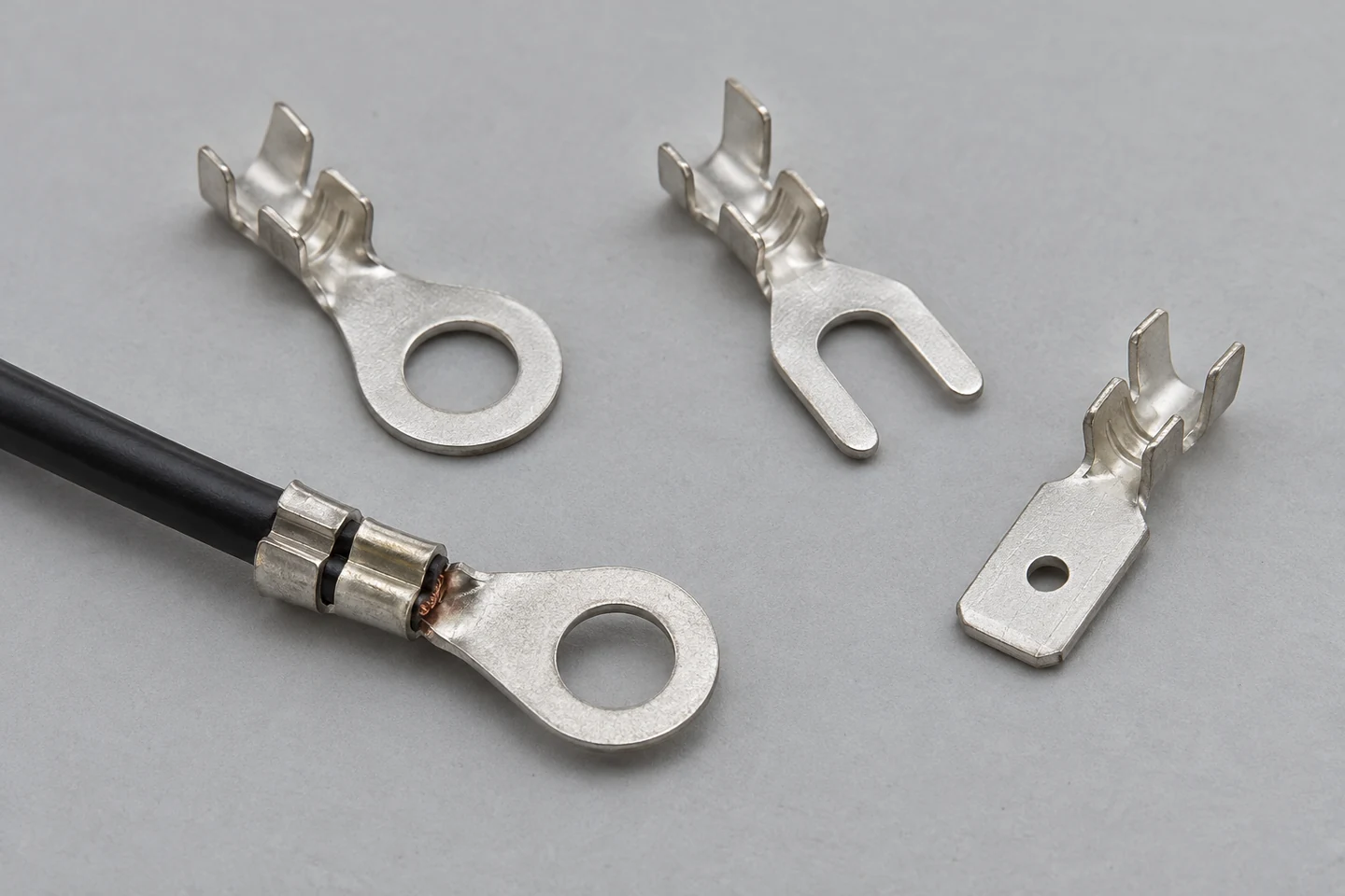
형상과 용도가 다른 압착단자 구성
접속 기능과 구조
외형·높이·내부 구조·기능 시험이 서로를 보완합니다.
압착단자는 금속 배럴을 변형시켜 도체를 유지하고 전류를 전달합니다. 전선이 빠지지 않는다는 사실만으로 낮고 안정적인 접속저항까지 확인되는 것은 아닙니다.
외관은 삽입과 성형 이상을 찾고, 크림프 하이트는 공정의 치수 상태를 보여 줍니다. 단면은 내부 배치를, 인장시험과 전기·환경시험은 서로 다른 기능을 확인합니다.
따라서 합격 기준은 지정된 전선·단자·툴링 조합에서 설정합니다. 하나의 좋은 검사 결과로 다른 시험을 자동 생략하지 않고 각 검사의 목적과 한계를 관리계획에 명시합니다.
삽입과 공정 상태 · 제품별 기준·측정법
날개·소선의 내부 배치 · 절단 위치·형상 판정
유지력·전기 안정성 · 시험 조건과 파손 모드
| 검토 항목 | 기술적 의미 | 검증·관리 기준 |
|---|---|---|
| 외관·하이트 | 삽입과 공정 상태 | 제품별 기준·측정법 |
| 단면 | 날개·소선의 내부 배치 | 절단 위치·형상 판정 |
| 기능 시험 | 유지력·전기 안정성 | 시험 조건과 파손 모드 |
외관·하이트
기술적 의미
삽입과 공정 상태
검증·관리 기준
제품별 기준·측정법
단면
기술적 의미
날개·소선의 내부 배치
검증·관리 기준
절단 위치·형상 판정
기능 시험
기술적 의미
유지력·전기 안정성
검증·관리 기준
시험 조건과 파손 모드
전류 경로와 굽힘 하중의 경로를 구분합니다.
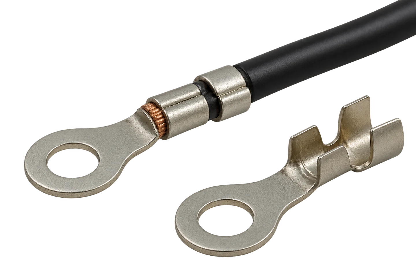
도체 압착부는 노출된 소선을 감싸 접촉과 기계적 유지를 만듭니다. 절연 압착부는 피복을 지지하며 전선의 굽힘이 도체 압착 경계에 집중되지 않도록 돕습니다.
피복이 도체 배럴 안에 들어가거나 소선이 바깥으로 빠지면 내부 충진이 달라집니다. 스트립 길이와 삽입 위치를 함께 관리하여 브러시, 전이 구간과 피복 지지가 각각 정해진 위치에 오도록 합니다.
절연 지지를 강하게 누르는 것으로 부족한 도체 압착을 보완하지 않습니다. 도체 유지력을 시험할 때는 적용 절차에 따라 절연 그립의 기여를 제거하고 두 기능을 구분해서 평가합니다.
전류와 유지력 · 소선 수·삽입·성형
피복과 노출부 경계 · 피복 혼입·과도 노출
전선의 기계적 지지 · 피복 손상·지지 상태
전류 경로와 굽힘 하중의 경로를 구분합니다.
전류와 유지력 · 소선 수·삽입·성형
| 검토 항목 | 기술적 의미 | 검증·관리 기준 |
|---|---|---|
| 도체 배럴 | 전류와 유지력 | 소선 수·삽입·성형 |
| 전이부 | 피복과 노출부 경계 | 피복 혼입·과도 노출 |
| 절연 그립 | 전선의 기계적 지지 | 피복 손상·지지 상태 |
도체 배럴
기술적 의미
전류와 유지력
검증·관리 기준
소선 수·삽입·성형
전이부
기술적 의미
피복과 노출부 경계
검증·관리 기준
피복 혼입·과도 노출
절연 그립
기술적 의미
전선의 기계적 지지
검증·관리 기준
피복 손상·지지 상태
조합과 입력 품질
같은 공칭 단면적도 같은 변형을 뜻하지 않습니다.
전선의 소선 수와 직경, 도체 재질·도금과 피복 외경은 배럴 충진과 지지 조건을 바꿉니다. 단자 소재 두께와 조질, 날개 길이, 서레이션과 도금도 성형 거동에 영향을 줍니다.
관리 단위에는 전선 품번, 단자 품번, 어플리케이터와 펀치·앤빌, 프레스를 포함합니다. 단자 도면의 적용 전선 범위를 확인하고 제조사 적용 사양에서 높이·스트립 길이·인장 기준을 찾습니다.
공급사 또는 소선 구성을 바꾸면 외형이 비슷해도 기존 승인 범위를 검토합니다. 승인되지 않은 윤활이나 도체 사전 납땜으로 공정 문제를 임의 보완하지 않습니다.
충진과 변형 · 품번·소선·재질·피복
배럴 성형 특성 · 두께·조질·도금
변형 경로 · 펀치·앤빌·어플리케이터
충진과 변형 · 품번·소선·재질·피복
| 검토 항목 | 기술적 의미 | 검증·관리 기준 |
|---|---|---|
| 전선 | 충진과 변형 | 품번·소선·재질·피복 |
| 단자 | 배럴 성형 특성 | 두께·조질·도금 |
| 툴링 | 변형 경로 | 펀치·앤빌·어플리케이터 |
| 프레스 | 스트로크 재현 | 설치·하사점·정비 |
전선
기술적 의미
충진과 변형
검증·관리 기준
품번·소선·재질·피복
단자
기술적 의미
배럴 성형 특성
검증·관리 기준
두께·조질·도금
툴링
기술적 의미
변형 경로
검증·관리 기준
펀치·앤빌·어플리케이터
프레스
기술적 의미
스트로크 재현
검증·관리 기준
설치·하사점·정비
도체 압착부와 별도의 절연 지지부
04 / 04
벨마우스와 브러시는 전선 위치의 단서입니다.
스트리핑 과정의 소선 절상·누락은 압착 전에 확인해야 합니다. 피복 제거 길이가 같아도 실제 삽입 깊이가 다르면 브러시와 전이부의 위치가 달라집니다.
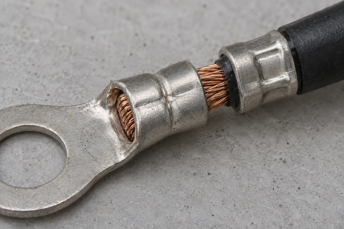
벨마우스는 배럴 입구의 완만한 전이로 소선이 날카로운 모서리에 손상될 가능성을 줄입니다. 필요한 위치와 크기는 단자 설계에 따르며 전후방 모두 같은 형상을 요구한다고 가정하지 않습니다.
도체 브러시는 유효 압착 구역을 지나도록 하되 접촉부를 침범하지 않아야 합니다. 컷오프 탭, 비대칭 플래시와 몸체 뒤틀림도 피드·정렬·공구 마모를 살펴볼 단서로 기록합니다.
벨마우스와 브러시는 전선 위치의 단서입니다.
| 검토 항목 | 기술적 의미 | 검증·관리 기준 |
|---|---|---|
| 소선 상태 | 스트리핑 손상 | 확대 관찰·누락 확인 |
| 벨마우스 | 입구 전이 | 위치·허용 범위 |
| 브러시 | 유효 길이 확보 | 짧음·과다·접촉부 침범 |
| 탭·플래시 | 절단·정렬 흔적 | 공구·피드 교차 확인 |
소선 상태
기술적 의미
스트리핑 손상
검증·관리 기준
확대 관찰·누락 확인
벨마우스
기술적 의미
입구 전이
검증·관리 기준
위치·허용 범위
브러시
기술적 의미
유효 길이 확보
검증·관리 기준
짧음·과다·접촉부 침범
탭·플래시
기술적 의미
절단·정렬 흔적
검증·관리 기준
공구·피드 교차 확인
배럴이 닫힌 B형 외형을 만들고 뒤쪽에서 피복을 지지합니다. 소선은 서로 겹치지 않도록 배치했습니다.
치수와 내부 형상
같은 치수 이름도 측정면이 다르면 값이 달라집니다.
크림프 하이트는 지정된 도체 압착부의 상면과 하부 반경면 사이에서 측정합니다. 벨마우스와 하부 플래시를 포함하지 않도록 제품별 측정 위치와 접촉 방향을 고정합니다.
블레이드·포인트형 측정면은 압착 형상에 맞는 접촉을 돕습니다. 시편 기울기, 과도한 측정력과 전선을 비틀어 잡는 자세는 반복성을 떨어뜨릴 수 있으므로 측정 작업을 표준화합니다.
게이지 분해능만으로 충분하다고 판단하지 않습니다. 교정, 반복성·재현성과 안정성을 확인하고 측정법이 다른 단면값과 외부 마이크로미터값을 무조건 같은 데이터로 합치지 않습니다.
유효 압착 높이 · 벨마우스·플래시 제외
접촉 위치의 재현 · 형상 적합·시편 자세
시편과 접촉의 영향 · 일정한 힘과 방법
유효 압착 높이 · 벨마우스·플래시 제외
| 검토 항목 | 기술적 의미 | 검증·관리 기준 |
|---|---|---|
| 측정점 | 유효 압착 높이 | 벨마우스·플래시 제외 |
| 측정면 | 접촉 위치의 재현 | 형상 적합·시편 자세 |
| 측정력 | 시편과 접촉의 영향 | 일정한 힘과 방법 |
| 측정시스템 | 공정 변동의 분리 | 교정·반복성·재현성 |
측정점
기술적 의미
유효 압착 높이
검증·관리 기준
벨마우스·플래시 제외
측정면
기술적 의미
접촉 위치의 재현
검증·관리 기준
형상 적합·시편 자세
측정력
기술적 의미
시편과 접촉의 영향
검증·관리 기준
일정한 힘과 방법
측정시스템
기술적 의미
공정 변동의 분리
검증·관리 기준
교정·반복성·재현성
공극의 크기 하나로 압착 전체를 판정하지 않습니다.
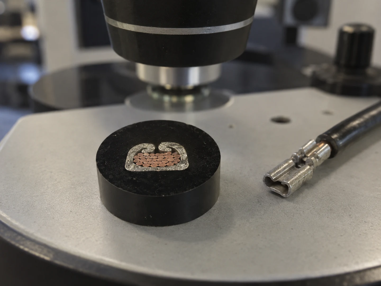
단면은 지정 위치에서 절단·마운팅·연마하여 준비합니다. 비스듬한 절단, 번짐과 가장자리 말림은 실제 날개 접촉이나 공극을 다르게 보이게 하므로 시편 준비 이력도 남깁니다.
배럴의 닫힘, 날개 말림과 지지, 바닥 두께, 소선의 분포·변형과 균열을 함께 봅니다. 날개가 바닥을 과도하게 파고들거나 일부 소선만 크게 눌렸는지 제품별 단면 기준으로 평가합니다.
좋은 단면은 공정 이해의 근거이지만 모든 위치와 모든 제품을 대표하지 않습니다. 이상 구간은 추가 절단으로 확인하고 높이·인장·저항 결과를 연결해 조정 방향을 정합니다.
관찰 구간의 대표성 · 유효 압착부·방향 지정
성형과 지지 · 닫힘·박화·균열
내부 충진 · 누락·편중·손상
관찰 구간의 대표성 · 유효 압착부·방향 지정
| 검토 항목 | 기술적 의미 | 검증·관리 기준 |
|---|---|---|
| 절단 위치 | 관찰 구간의 대표성 | 유효 압착부·방향 지정 |
| 날개·바닥 | 성형과 지지 | 닫힘·박화·균열 |
| 소선 분포 | 내부 충진 | 누락·편중·손상 |
| 시편 준비 | 관찰 왜곡 가능성 | 번짐·기울기·재연마 |
절단 위치
기술적 의미
관찰 구간의 대표성
검증·관리 기준
유효 압착부·방향 지정
날개·바닥
기술적 의미
성형과 지지
검증·관리 기준
닫힘·박화·균열
소선 분포
기술적 의미
내부 충진
검증·관리 기준
누락·편중·손상
시편 준비
기술적 의미
관찰 왜곡 가능성
검증·관리 기준
번짐·기울기·재연마
마운팅된 압착 단면의 현미경 검사 구성
유지력과 통계
최대 하중은 파손이 일어난 위치와 함께 해석합니다.
인장시험은 도체 압착의 기계적 유지력을 확인합니다. 절연 그립의 영향을 제거하는 방법, 인장 속도와 고정 지그는 적용 규격과 제품 사양에 맞춰 정합니다.
도체 인발, 압착 경계의 절손, 자유 전선 파단과 단자 파손은 서로 다른 정보를 줍니다. 지그의 편심이나 미끄러짐으로 생긴 손상을 실제 압착부의 파손으로 오인하지 않도록 합니다.
최소 인장력과 합격 모드는 조합별 기준을 따릅니다. 전선이 끊어졌다는 이유만으로 자동 합격시키거나 큰 힘을 얻기 위해 하이트를 계속 낮추지 않으며, 전기·환경 성능은 별도로 확인합니다.
도체 유지력의 분리 · 절연 그립 처리·지그
시험 간 비교 · 속도·축 정렬·교정
원인 해석 · 인발·경계·전선·단자
최대 하중은 파손이 일어난 위치와 함께 해석합니다.
도체 유지력의 분리 · 절연 그립 처리·지그
| 검토 항목 | 기술적 의미 | 검증·관리 기준 |
|---|---|---|
| 시험 준비 | 도체 유지력의 분리 | 절연 그립 처리·지그 |
| 인장 조건 | 시험 간 비교 | 속도·축 정렬·교정 |
| 파손 위치 | 원인 해석 | 인발·경계·전선·단자 |
| 판정 | 제품 요구와 연결 | 최소 하중·허용 모드 |
시험 준비
기술적 의미
도체 유지력의 분리
검증·관리 기준
절연 그립 처리·지그
인장 조건
기술적 의미
시험 간 비교
검증·관리 기준
속도·축 정렬·교정
파손 위치
기술적 의미
원인 해석
검증·관리 기준
인발·경계·전선·단자
판정
기술적 의미
제품 요구와 연결
검증·관리 기준
최소 하중·허용 모드
닫힌 배럴의 외형과 다이 공동이 맞고 바닥은 앤빌 상면에 놓입니다. 공구가 내부 소선을 관통하지 않습니다.
Cpk는 조건이 맞는 한 특성의 분포를 요약합니다.
공정능력은 관리 상태가 확인된 공정의 변동을 규격과 비교하는 단계입니다. 높이가 시간에 따라 이동하거나 여러 셋업이 섞여 있으면 하나의 Cpk가 그 변화를 숨길 수 있습니다.
양측 규격의 통상적인 Cpk 해석에는 안정성, 적절한 표본 구성과 대략적인 정규분포 가정이 필요합니다. σ의 추정 방식과 수집 기간을 명시하고 단측 인장력 기준에 양측 높이 계산을 그대로 적용하지 않습니다.
아래 수치는 계산 방법만 보여 주는 가정입니다. 높은 높이 Cpk가 단면·인장·저항 합격을 대신하지 않으며, 합격 목표와 신뢰구간·표본 수는 고객 요구와 데이터 조건에 맞춰 정합니다.
USL·LSL: 양측 높이 규격[mm], μ: 안정된 공정 평균[mm], σ: 정의한 방식으로 추정한 공정 표준편차[mm]. 설명용으로 LSL=1.00, USL=1.10, μ=1.06, σ=0.010 mm이면 Cpk=min(1.33,2.00)=1.33입니다. 통계적으로 안정되고 대략 정규분포인 단일 공정과 타당한 측정시스템을 가정합니다. 실제 단자의 높이·공차·합격 목표를 지정하는 예가 아닙니다.
시간에 따른 공정 상태 · 관리도와 변경 이력
| 검토 항목 | 기술적 의미 | 검증·관리 기준 |
|---|---|---|
| 안정성 | 시간에 따른 공정 상태 | 관리도와 변경 이력 |
| 규격 | 허용 제품 범위 | 관리한계와 구분 |
| σ 추정 | 변동의 정의 | 부분군·기간·방법 명시 |
| 해석 범위 | 한 특성의 능력 | 기능 시험과 별도 판정 |
안정성
기술적 의미
시간에 따른 공정 상태
검증·관리 기준
관리도와 변경 이력
규격
기술적 의미
허용 제품 범위
검증·관리 기준
관리한계와 구분
σ 추정
기술적 의미
변동의 정의
검증·관리 기준
부분군·기간·방법 명시
해석 범위
기술적 의미
한 특성의 능력
검증·관리 기준
기능 시험과 별도 판정
공정 신호와 환경
기준 파형과 비슷하다는 사실이 모든 결함의 부재를 뜻하지는 않습니다.
압착력 모니터는 힘–시간 또는 힘–위치 신호를 비교하여 스트로크의 변화를 찾습니다. 신호에는 도체 압축뿐 아니라 단자 성형, 절단과 공구 마찰의 기여가 함께 포함됩니다.
기준 파형은 높이·외관·단면·인장 등으로 확인된 양품에서 설정합니다. 소선 누락, 피복 혼입이나 이송 이상을 실제 조합에서 의도적으로 만들어 검출 가능 범위와 오검출을 평가해야 합니다.
재료나 공구가 바뀌면 기준선도 움직일 수 있습니다. 경보를 줄이기 위해 허용폭을 넓히거나 기준을 자동으로 덮어쓰기 전에 원인을 확인하고 필요한 제품을 격리합니다.
기준 파형과 비슷하다는 사실이 모든 결함의 부재를 뜻하지는 않습니다.
검증된 양품 신호 · 샘플 승인과 버전
| 검토 항목 | 기술적 의미 | 검증·관리 기준 |
|---|---|---|
| 기준 파형 | 검증된 양품 신호 | 샘플 승인과 버전 |
| 결함 검출 | 검출 가능한 이상 범위 | 의도 결함 시험 |
| 센서·정렬 | 신호 재현성 | 고정·잡음·위치 동기 |
| 경보 대응 | 공정 이상 관리 | 격리·원인·재시작 확인 |
기준 파형
기술적 의미
검증된 양품 신호
검증·관리 기준
샘플 승인과 버전
결함 검출
기술적 의미
검출 가능한 이상 범위
검증·관리 기준
의도 결함 시험
센서·정렬
기술적 의미
신호 재현성
검증·관리 기준
고정·잡음·위치 동기
경보 대응
기술적 의미
공정 이상 관리
검증·관리 기준
격리·원인·재시작 확인
초기 저항과 노출 후 저항을 같은 조건에서 비교합니다.
전기 저항은 측정 구간과 리드 접촉을 정의하고 작은 저항에 적합한 4단자 방식 등을 사용합니다. 전선 자체 저항의 포함 범위와 시험 전류·온도가 달라지면 서로 다른 값을 직접 비교하기 어렵습니다.
전류 부하·열 사이클·습도·진동 후의 변화를 실제 사용 조건과 연결합니다. 초기 인장력이나 저항이 좋다는 이유로 장기 접속 안정성을 자동 보증하지 않습니다.
윤활량이 압착 높이에 영향을 줄 수 있으므로 전기·기계 기준의 충족 여부와 함께 확인합니다. 높이 변화만으로 윤활의 적합성을 판단하지 않고 승인된 윤활제 종류·적용량을 관리하며 제품별로 재검증합니다.
정의된 접속 구간 · 4단자·전류·온도
사용 중 변화 · 전후 값과 시험 순서
마찰·변형 변화 · 승인 종류·양·위치
정의된 접속 구간 · 4단자·전류·온도
| 검토 항목 | 기술적 의미 | 검증·관리 기준 |
|---|---|---|
| 저항 측정 | 정의된 접속 구간 | 4단자·전류·온도 |
| 환경 노출 | 사용 중 변화 | 전후 값과 시험 순서 |
| 윤활 | 마찰·변형 변화 | 승인 종류·양·위치 |
| 기능 승인 | 장기 요구와 연결 | 제품별 시험 범위 |
저항 측정
기술적 의미
정의된 접속 구간
검증·관리 기준
4단자·전류·온도
환경 노출
기술적 의미
사용 중 변화
검증·관리 기준
전후 값과 시험 순서
윤활
기술적 의미
마찰·변형 변화
검증·관리 기준
승인 종류·양·위치
기능 승인
기술적 의미
장기 요구와 연결
검증·관리 기준
제품별 시험 범위
문제 해결과 양산
하이트 조정 전에 재료·피드·공구를 함께 확인합니다.
하이트 상승이 보이면 단순히 다이를 더 닫기 전에 소선 누락, 소재 로트, 프레스 설치와 공구 상태를 확인합니다. 하이트 저하와 플래시 증가도 과압착뿐 아니라 마모·정렬 이상과 연결될 수 있습니다.
인장력 저하는 스트리핑 절상, 유효 길이 부족, 잘못된 조합이나 시험 고정에서 비롯될 수 있습니다. 단면과 파손 위치를 함께 보면 설정 변경이 필요한지 입력 재료를 바로잡아야 하는지 판단하기 쉽습니다.
조치는 격리 범위, 수정 내용과 재시작 검증으로 닫습니다. 변경 전후의 결과를 보존해야 재발 시 같은 현상을 새 문제처럼 반복해서 다루지 않을 수 있습니다.
조건·재료 변화 · 자재·툴·프레스 확인
내부 성형 변화 · 피드·정렬·소선
유지력·시험 문제 · 파손 위치와 지그
하이트 조정 전에 재료·피드·공구를 함께 확인합니다.
조건·재료 변화 · 자재·툴·프레스 확인
| 검토 항목 | 기술적 의미 | 검증·관리 기준 |
|---|---|---|
| 높이 이동 | 조건·재료 변화 | 자재·툴·프레스 확인 |
| 단면 이상 | 내부 성형 변화 | 피드·정렬·소선 |
| 인장 저하 | 유지력·시험 문제 | 파손 위치와 지그 |
| 재시작 | 수정의 유효성 | 초품·기능·기록 승인 |
높이 이동
기술적 의미
조건·재료 변화
검증·관리 기준
자재·툴·프레스 확인
단면 이상
기술적 의미
내부 성형 변화
검증·관리 기준
피드·정렬·소선
인장 저하
기술적 의미
유지력·시험 문제
검증·관리 기준
파손 위치와 지그
재시작
기술적 의미
수정의 유효성
검증·관리 기준
초품·기능·기록 승인
검사 시점과 변경 범위가 정해져야 품질이 반복됩니다.
셋업, 자재 로트 전환, 툴 교체와 정비 뒤에 무엇을 검사할지 정합니다. 초품 확인과 주기 검사, 경보 발생 시의 격리 범위를 전선·단자·공구 조합별로 문서화합니다.
기록에는 높이 분포, 단면 위치, 인장력·파손 모드, 기준 파형과 제품 이력을 연결합니다. 숫자만 남기지 않고 측정법과 사양 개정도 함께 보존해야 데이터의 비교가 가능합니다.
제작 검토에는 전선 구조·피복 외경, 단자 도면과 도금, 장비·툴링, 사용 전류·온도·진동 및 합격 기준을 전달합니다. 이 입력이 갖춰져야 적절한 공정 창과 검증 범위를 협의할 수 있습니다.
변경 직후 위험 · 셋업·로트·툴·정비
승인 범위 · 도면·적용 사양 개정
영향 로트 식별 · 자재·시간·설비 연결
변경 직후 위험 · 셋업·로트·툴·정비
| 검토 항목 | 기술적 의미 | 검증·관리 기준 |
|---|---|---|
| 검사 시점 | 변경 직후 위험 | 셋업·로트·툴·정비 |
| 사양 관리 | 승인 범위 | 도면·적용 사양 개정 |
| 제품 추적 | 영향 로트 식별 | 자재·시간·설비 연결 |
| 개발 협의 | 공정 창 정의 | 사용 조건·합격 시험 |
검사 시점
기술적 의미
변경 직후 위험
검증·관리 기준
셋업·로트·툴·정비
사양 관리
기술적 의미
승인 범위
검증·관리 기준
도면·적용 사양 개정
제품 추적
기술적 의미
영향 로트 식별
검증·관리 기준
자재·시간·설비 연결
개발 협의
기술적 의미
공정 창 정의
검증·관리 기준
사용 조건·합격 시험
전선·단자 품번, 소선 구성·피복 외경과 적용 툴링·시험 기준을 전달해 주세요.
Share wire and terminal part numbers, strand construction, jacket diameter, tooling and acceptance tests.
TERMINAL CRIMP QUALITY
Explore wire insertion, wing closure, and the approach and withdrawal of forming tools.
Height · Section · Pull · Cpk
ENGLISH EDITION
Crimp control that connects measurement with function
One press stroke creates several quality characteristics at once. Judging a terminal only by height or pull force can miss internal geometry and electrical changes.
Start with the wire–terminal–tool combination and connect measurement, section analysis, functional testing and process monitoring.
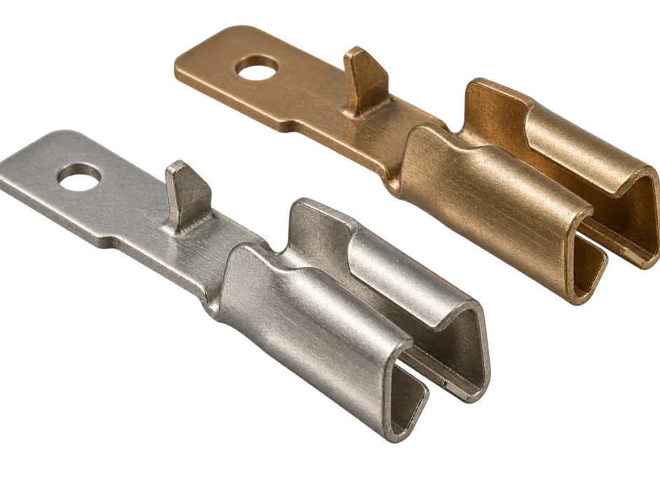
Crimp terminals with different contact geometries
Connection function and structure
Appearance, height, internal structure and function complement each other.
A crimp terminal retains a conductor and carries current by deforming its metal barrel. Resistance to pullout alone does not establish low, stable electrical resistance.
Visual inspection identifies insertion and forming defects, while crimp height describes a dimensional process condition. Sections reveal internal arrangement; pull, electrical and environmental tests verify different functions.
Establish acceptance for the specified wire, terminal and tooling combination. One favorable result does not automatically replace the other checks; document the purpose and limits of each in the control plan.
Insertion and process condition. Product criteria and measurement method
Wing and strand arrangement. Cut location and geometry assessment
Retention and electrical stability. Test conditions and failure modes
| Review item | Engineering significance | Verification or control |
|---|---|---|
| Appearance and height | Insertion and process condition | Product criteria and measurement method |
| Section | Wing and strand arrangement | Cut location and geometry assessment |
| Functional tests | Retention and electrical stability | Test conditions and failure modes |
Appearance and height
Engineering significance
Insertion and process condition
Verification or control
Product criteria and measurement method
Section
Engineering significance
Wing and strand arrangement
Verification or control
Cut location and geometry assessment
Functional tests
Engineering significance
Retention and electrical stability
Verification or control
Test conditions and failure modes
Separate the electrical path from the support for bending loads.
The conductor crimp surrounds exposed strands to form electrical contact and mechanical retention. The insulation crimp supports the jacket and helps prevent bending from concentrating at the conductor-crimp boundary.
Insulation inside the conductor barrel or escaped strands changes internal filling. Control strip length and insertion together so that the brush, transition and insulation support occupy their specified positions.
A tight insulation grip cannot compensate for an inadequate conductor crimp. When testing conductor retention, remove the contribution of the insulation grip as required by the applicable method and assess the two functions separately.
Current and retention. Strand count, insertion and forming
Jacket-to-bare-wire boundary. Insulation intrusion and excessive exposure
Mechanical wire support. Jacket damage and support
Separate the electrical path from the support for bending loads.
Current and retention. Strand count, insertion and forming
| Review item | Engineering significance | Verification or control |
|---|---|---|
| Conductor barrel | Current and retention | Strand count, insertion and forming |
| Transition | Jacket-to-bare-wire boundary | Insulation intrusion and excessive exposure |
| Insulation grip | Mechanical wire support | Jacket damage and support |
Conductor barrel
Engineering significance
Current and retention
Verification or control
Strand count, insertion and forming
Transition
Engineering significance
Jacket-to-bare-wire boundary
Verification or control
Insulation intrusion and excessive exposure
Insulation grip
Engineering significance
Mechanical wire support
Verification or control
Jacket damage and support
Combination and input quality
Equal nominal wire area does not imply equal deformation.
Strand count and diameter, conductor material and finish, and jacket diameter change barrel filling and support. Terminal thickness, temper, wing length, serrations and finish also affect forming.
The controlled combination includes wire and terminal part numbers, applicator, punch and anvil, and press. Check the permitted wire range and obtain height, strip-length and pull requirements from the applicable specification.
Review qualification after changing suppliers or strand construction, even when appearance is similar. Do not improvise unapproved lubrication or pre-tinning to compensate for a process problem.
Filling and deformation. Part, strands, material and jacket
Barrel-forming behavior. Thickness, temper and finish
Deformation path. Punch, anvil and applicator
Filling and deformation. Part, strands, material and jacket
| Review item | Engineering significance | Verification or control |
|---|---|---|
| Wire | Filling and deformation | Part, strands, material and jacket |
| Terminal | Barrel-forming behavior | Thickness, temper and finish |
| Tooling | Deformation path | Punch, anvil and applicator |
| Press | Stroke repeatability | Installation, bottom position and maintenance |
Wire
Engineering significance
Filling and deformation
Verification or control
Part, strands, material and jacket
Terminal
Engineering significance
Barrel-forming behavior
Verification or control
Thickness, temper and finish
Tooling
Engineering significance
Deformation path
Verification or control
Punch, anvil and applicator
Press
Engineering significance
Stroke repeatability
Verification or control
Installation, bottom position and maintenance
Conductor crimp and separate insulation support
04 / 04
Bellmouth and brush provide evidence of wire positioning.
Inspect strand nicks and omissions before crimping. Equal strip lengths can still produce different brush and transition positions when insertion depth changes.
The bellmouth provides a gradual barrel entrance that reduces damage from a sharp edge. Its required location and size depend on terminal design; do not assume identical front and rear requirements.
The conductor brush should extend beyond the effective crimp without intruding into the contact region. Record cut-off tabs, asymmetric flash and body distortion as evidence for reviewing feed, alignment and tool wear.
Bellmouth and brush provide evidence of wire positioning.
| Review item | Engineering significance | Verification or control |
|---|---|---|
| Strand condition | Stripping damage | Magnification and missing-strand checks |
| Bellmouth | Entrance transition | Location and permitted range |
| Brush | Effective conductor length | Short, excessive or contact-region intrusion |
| Tab and flash | Cutting and alignment evidence | Cross-check tooling and feed |
Strand condition
Engineering significance
Stripping damage
Verification or control
Magnification and missing-strand checks
Bellmouth
Engineering significance
Entrance transition
Verification or control
Location and permitted range
Brush
Engineering significance
Effective conductor length
Verification or control
Short, excessive or contact-region intrusion
Tab and flash
Engineering significance
Cutting and alignment evidence
Verification or control
Cross-check tooling and feed
The barrel closes into a B-style envelope and supports the jacket separately. Strands are placed without mutual overlap.
Dimensions and internal geometry
The same dimension name can hide different contact locations.
Measure crimp height between the specified top surface and lower radial surface of the conductor crimp. Standardize location and contact direction so that bellmouth and bottom flash are excluded.
Blade-and-point contacts help fit the measurement to the crimp geometry. Tilt, excessive measuring force and twisting the wire can reduce repeatability, so standardize how the sample is held and measured.
Resolution alone does not establish adequacy. Check calibration, repeatability, reproducibility and stability, and do not combine section-based and external micrometer measurements without demonstrating their relationship.
Effective crimp height. Exclude bellmouth and flash
Repeatable contact points. Suitable geometry and specimen position
Influence on sample and contact. Consistent force and method
Effective crimp height. Exclude bellmouth and flash
| Review item | Engineering significance | Verification or control |
|---|---|---|
| Location | Effective crimp height | Exclude bellmouth and flash |
| Contacts | Repeatable contact points | Suitable geometry and specimen position |
| Force | Influence on sample and contact | Consistent force and method |
| Measurement system | Separate process variation | Calibration, repeatability and reproducibility |
Location
Engineering significance
Effective crimp height
Verification or control
Exclude bellmouth and flash
Contacts
Engineering significance
Repeatable contact points
Verification or control
Suitable geometry and specimen position
Force
Engineering significance
Influence on sample and contact
Verification or control
Consistent force and method
Measurement system
Engineering significance
Separate process variation
Verification or control
Calibration, repeatability and reproducibility
Void size alone cannot qualify a crimp.
Prepare sections by cutting, mounting and polishing at the defined location. Oblique cuts, smearing and edge rounding can distort the apparent wing contact or voids, so retain preparation records.
Review barrel closure, curled-wing support, bottom thickness, strand distribution and deformation, and cracks together. Assess excessive wing penetration or uneven strand compression against the product-specific section criteria.
A sound section helps explain the process but does not represent every location or every unit. Examine suspect regions with additional sections and connect the result with height, pull and resistance data before adjusting the process.
Representative observation. Define region and orientation
Forming and support. Closure, thinning and cracks
Internal filling. Missing, uneven or damaged strands
Representative observation. Define region and orientation
| Review item | Engineering significance | Verification or control |
|---|---|---|
| Cut location | Representative observation | Define region and orientation |
| Wings and bottom | Forming and support | Closure, thinning and cracks |
| Strands | Internal filling | Missing, uneven or damaged strands |
| Preparation | Potential imaging artifacts | Smearing, tilt and repolishing |
Cut location
Engineering significance
Representative observation
Verification or control
Define region and orientation
Wings and bottom
Engineering significance
Forming and support
Verification or control
Closure, thinning and cracks
Strands
Engineering significance
Internal filling
Verification or control
Missing, uneven or damaged strands
Preparation
Engineering significance
Potential imaging artifacts
Verification or control
Smearing, tilt and repolishing
Microscope setup for a mounted crimp section
Retention and statistics
Interpret peak load together with where failure occurred.
Pull testing verifies mechanical retention of the conductor crimp. Set insulation-grip treatment, test speed and fixtures according to the applicable standard and product specification.
Wire pullout, fracture at the crimp boundary, free-wire fracture and terminal rupture provide different information. Distinguish damage from fixture misalignment or slipping from failure of the crimp itself.
Apply combination-specific minimum force and failure criteria. A broken wire is not an automatic pass, and continually lowering height to increase force is inappropriate. Verify electrical and environmental performance separately.
Isolate conductor retention. Insulation-grip treatment and fixtures
Comparable results. Speed, axial alignment and calibration
Interpret causes. Pullout, boundary, wire or terminal
Interpret peak load together with where failure occurred.
Isolate conductor retention. Insulation-grip treatment and fixtures
| Review item | Engineering significance | Verification or control |
|---|---|---|
| Preparation | Isolate conductor retention | Insulation-grip treatment and fixtures |
| Test conditions | Comparable results | Speed, axial alignment and calibration |
| Failure location | Interpret causes | Pullout, boundary, wire or terminal |
| Acceptance | Link to product requirements | Minimum load and permitted modes |
Preparation
Engineering significance
Isolate conductor retention
Verification or control
Insulation-grip treatment and fixtures
Test conditions
Engineering significance
Comparable results
Verification or control
Speed, axial alignment and calibration
Failure location
Engineering significance
Interpret causes
Verification or control
Pullout, boundary, wire or terminal
Acceptance
Engineering significance
Link to product requirements
Verification or control
Minimum load and permitted modes
The closed barrel fits the die cavity and sits on the anvil; the tool does not pass through the strands.
Cpk summarizes one characteristic under defined assumptions.
Capability compares variation from an in-control process with specifications. If height drifts over time or different setups are pooled, a single Cpk can conceal those changes.
Conventional interpretation for two-sided specifications requires stability, appropriate sampling and approximately normal data. State how sigma is estimated and the collection period; do not transfer this two-sided height calculation directly to a one-sided pull requirement.
The numbers below illustrate the calculation only. A high height Cpk does not replace section, pull or resistance acceptance. Set targets, confidence treatment and sample size according to requirements and the data conditions.
USL and LSL: two-sided height specifications [mm]; μ: stable-process mean [mm]; σ: process standard deviation estimated by a stated method [mm]. For illustrative LSL=1.00, USL=1.10, μ=1.06 and σ=0.010 mm, Cpk=min(1.33,2.00)=1.33. This assumes one statistically stable, approximately normal process and an adequate measurement system. It does not prescribe a terminal height, tolerance or capability target.
Process condition over time. Control charts and change history
| Review item | Engineering significance | Verification or control |
|---|---|---|
| Stability | Process condition over time | Control charts and change history |
| Specifications | Permitted product range | Separate from control limits |
| Sigma estimate | Definition of variation | State subgroup, period and method |
| Interpretation | Capability of one characteristic | Separate functional acceptance |
Stability
Engineering significance
Process condition over time
Verification or control
Control charts and change history
Specifications
Engineering significance
Permitted product range
Verification or control
Separate from control limits
Sigma estimate
Engineering significance
Definition of variation
Verification or control
State subgroup, period and method
Interpretation
Engineering significance
Capability of one characteristic
Verification or control
Separate functional acceptance
Process signals and environment
Similarity to a reference curve does not establish absence of every defect.
Crimp-force monitors compare force–time or force–position signals to identify stroke changes. The signal includes terminal forming, cut-off and tool friction as well as conductor compression.
Establish the reference from crimps qualified by appropriate height, appearance, section and pull checks. Challenge the actual combination with missing strands, insulation intrusion or feed defects to establish detection and false-reject behavior.
Material and tooling changes can shift the reference. Investigate the cause and contain affected product before widening limits or replacing the baseline simply to reduce alarms.
Similarity to a reference curve does not establish absence of every defect.
Qualified good-product signal. Approved samples and version
| Review item | Engineering significance | Verification or control |
|---|---|---|
| Reference curve | Qualified good-product signal | Approved samples and version |
| Detection | Range of detectable faults | Seeded-defect challenge |
| Sensor and alignment | Signal repeatability | Mounting, noise and position synchronization |
| Alarm response | Manage process abnormalities | Containment, cause and restart verification |
Reference curve
Engineering significance
Qualified good-product signal
Verification or control
Approved samples and version
Detection
Engineering significance
Range of detectable faults
Verification or control
Seeded-defect challenge
Sensor and alignment
Engineering significance
Signal repeatability
Verification or control
Mounting, noise and position synchronization
Alarm response
Engineering significance
Manage process abnormalities
Verification or control
Containment, cause and restart verification
Compare initial and post-exposure resistance consistently.
Define the resistance span and lead contacts, using a suitable low-resistance method such as four-terminal measurement. Different included wire lengths, current or temperature make direct comparisons unreliable.
Connect changes after current loading, thermal cycles, humidity and vibration to service conditions. Good initial pull force or resistance does not automatically establish long-term stability.
Lubrication level can affect crimp height, so evaluate height changes together with electrical and mechanical acceptance. A height change alone does not establish lubricant suitability: control the approved type and amount and validate the particular product.
Defined connection span. Four terminals, current and temperature
Changes during service. Before/after values and test sequence
Friction and deformation. Approved type, amount and location
Defined connection span. Four terminals, current and temperature
| Review item | Engineering significance | Verification or control |
|---|---|---|
| Resistance | Defined connection span | Four terminals, current and temperature |
| Environment | Changes during service | Before/after values and test sequence |
| Lubrication | Friction and deformation | Approved type, amount and location |
| Qualification | Long-term requirements | Product-specific test coverage |
Resistance
Engineering significance
Defined connection span
Verification or control
Four terminals, current and temperature
Environment
Engineering significance
Changes during service
Verification or control
Before/after values and test sequence
Lubrication
Engineering significance
Friction and deformation
Verification or control
Approved type, amount and location
Qualification
Engineering significance
Long-term requirements
Verification or control
Product-specific test coverage
Troubleshooting and production
Check material, feed and tooling before adjusting height.
When height rises, check strand omissions, material lot, press installation and tooling before simply closing the die further. Low height and excessive flash can involve wear or misalignment as well as over-crimping.
Low pull force can arise from stripping damage, insufficient effective length, an incorrect combination or test fixturing. Sections and failure locations help distinguish a setup correction from an input-material problem.
Close the action with containment boundaries, recorded corrections and restart verification. Retain before-and-after evidence so that recurrence can be recognized and addressed systematically.
Condition or material change. Check stock, tooling and press
Internal forming change. Feed, alignment and strands
Retention or test issue. Failure location and fixture
Check material, feed and tooling before adjusting height.
Condition or material change. Check stock, tooling and press
| Review item | Engineering significance | Verification or control |
|---|---|---|
| Height shift | Condition or material change | Check stock, tooling and press |
| Section defect | Internal forming change | Feed, alignment and strands |
| Low pull | Retention or test issue | Failure location and fixture |
| Restart | Effectiveness of correction | First-off, function and record review |
Height shift
Engineering significance
Condition or material change
Verification or control
Check stock, tooling and press
Section defect
Engineering significance
Internal forming change
Verification or control
Feed, alignment and strands
Low pull
Engineering significance
Retention or test issue
Verification or control
Failure location and fixture
Restart
Engineering significance
Effectiveness of correction
Verification or control
First-off, function and record review
Repeatability requires defined inspection events and change boundaries.
Define checks after setup, material-lot changes, tooling replacement and maintenance. Document first-off checks, periodic inspection and alarm containment for each wire–terminal–tool combination.
Link height distributions, section locations, pull forces and failure modes, reference curves and product history. Retain methods and specification revisions as well as numbers so that comparisons remain meaningful.
Provide wire construction and jacket diameter, terminal drawings and finish, equipment and tooling, service current, temperature and vibration, and acceptance requirements. These inputs support agreement on a suitable process window and validation scope.

Risk after changes. Setup, lots, tooling and service
Approved scope. Drawing and application revisions
Identify affected lots. Material, time and equipment links
Risk after changes. Setup, lots, tooling and service
| Review item | Engineering significance | Verification or control |
|---|---|---|
| Inspection events | Risk after changes | Setup, lots, tooling and service |
| Specification control | Approved scope | Drawing and application revisions |
| Traceability | Identify affected lots | Material, time and equipment links |
| Development review | Define a process window | Service conditions and acceptance tests |
Inspection events
Engineering significance
Risk after changes
Verification or control
Setup, lots, tooling and service
Specification control
Engineering significance
Approved scope
Verification or control
Drawing and application revisions
Traceability
Engineering significance
Identify affected lots
Verification or control
Material, time and equipment links
Development review
Engineering significance
Define a process window
Verification or control
Service conditions and acceptance tests
압착 품질은 승인된 조합과 반복 가능한 측정, 서로 보완하는 기능 시험에서 만들어집니다. 하이트는 중요한 관리특성이지만 단면·유지력·전기 안정성과 같은 의미는 아닙니다.
01 / 전선·단자·어플리케이터·프레스를 조합으로 관리합니다.
02 / 스트리핑 손상과 피복 혼입을 압착 전후 확인합니다.
03 / 지정 위치에서 벨마우스·플래시를 제외해 높이를 측정합니다.
04 / 단면은 날개·바닥·소선과 시편 준비를 함께 봅니다.
05 / 인장력은 절연 그립의 영향과 파손 모드를 구분합니다.
06 / Cpk 해석 전에 안정성·분포·측정시스템을 확인합니다.
07 / CFM 검출성을 실제 결함으로 확인하고 변경을 기록합니다.
과도한 압축은 소선 손상·박화·균열을 만들 수 있습니다. 해당 조합의 승인 범위를 따릅니다.
소선 수·도금·피복과 단자 형상이 다를 수 있습니다. 승인된 품번 조합을 확인합니다.
공극만으로 판정하지 않습니다. 날개 접촉, 소선 손상, 바닥과 기능 시험을 함께 봅니다.
파단 하중과 위치가 기준에 맞아야 합니다. 시험 지그에 의한 손상도 구분합니다.
도체 압착 유지력 평가는 적용 절차에 따라 절연 지지의 기여를 제거합니다. 제품 시험법을 확인합니다.
그 수치는 정의된 한 특성의 분포를 나타냅니다. 단면·전기·환경 성능을 대신하지 않습니다.
전선·단자·공구·센서 조합에 따라 다릅니다. 의도 결함 시험으로 실제 검출 범위를 확인합니다.
승인된 종류·양·위치를 따릅니다. 다른 제품의 실험 결과로 임의 도포를 정당화하지 않습니다.
높이의 공정 변동과 측정 변동을 구분합니다.
내부 형상을 인장·저항 결과와 연결합니다.
로트·공구·기준 파형의 관계를 남깁니다.
압착단자크림프 하이트단면 검사인장력벨마우스도체 브러시소선 손상압착력 모니터공정능력접속저항추적성
Crimp quality depends on an approved combination, repeatable measurement and complementary functional tests. Height is a key process characteristic, but it is distinct from internal geometry, retention and electrical stability.
01 / Control wire, terminal, applicator and press as a combination.
02 / Check stripping damage and insulation intrusion.
03 / Measure the specified height location excluding bellmouth and flash.
04 / Assess wings, bottom, strands and section preparation together.
05 / Separate insulation support and failure mode in pull testing.
06 / Establish stability, distribution and measurement adequacy before Cpk.
07 / Challenge CFM with actual defects and record changes.
Excessive compression can damage strands, thin the barrel or cause cracks. Use the approved range for the combination.
Strand construction, plating, jacket and terminal geometry can differ. Verify the approved part-number combination.
Not by itself. Review wings, strand damage, bottom condition and functional results.
Load and failure location must meet the requirements. Distinguish fixture-induced damage.
For conductor-crimp retention, remove its contribution according to the applicable method. Check the product test specification.
It describes the distribution of one defined characteristic. It does not replace section, electrical or environmental verification.
Detection depends on the wire, terminal, tool and sensor combination. Establish the actual range with seeded-defect tests.
Follow the approved type, amount and location. Results from another product do not authorize arbitrary application.
Separate process and measurement variation in height.
Connect internal geometry to pull and resistance results.
Retain relationships among lots, tooling and reference curves.
crimp terminalcrimp heightsection analysispull forcebellmouthconductor brushstrand damagecrimp-force monitoringprocess capabilityconnection resistancetraceability
연결 준비 중입니다. 현재 전화 연결을 이용하실 수 있습니다.