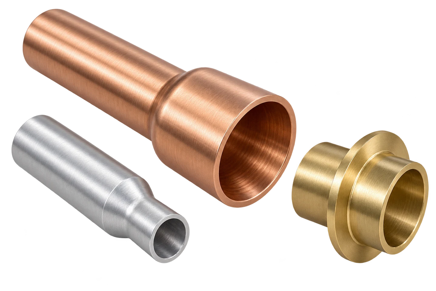
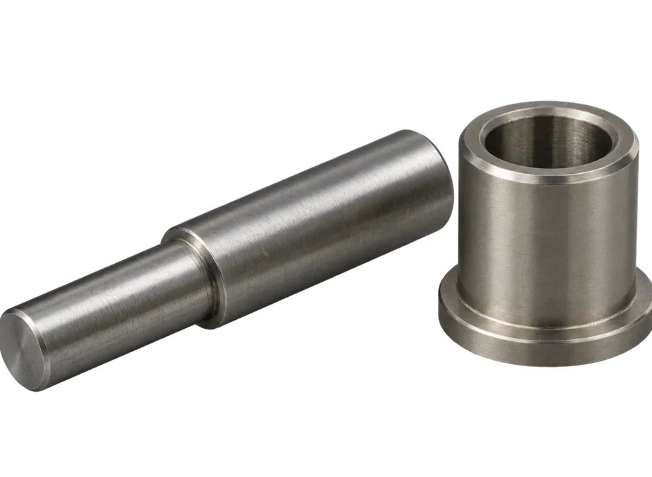
확관 구리관·축관 알루미늄관·플랜지 슬리브

TUBE SLEEVE FORMING

비철 튜브·슬리브
성형의 정밀함

축관·확관·최소벽에서 브레이징과 누설 검증까지

확관 구리관·축관 알루미늄관·플랜지 슬리브

Tube.
Form.
Fit.

TUBE SLEEVE FORMING

확관 구리관·축관 알루미늄관·플랜지 슬리브

Tube & Sleeve
Forming Engineering

직경·벽두께·표면·열 이력을 연결하여 성형과 접합을 하나의 공정으로 검토합니다.

Swaging · Expansion · Wall thickness · Joint integrity

Overview.

형상의 정밀함이 연결의 신뢰성으로.

비철 슬리브의 완성도는 외경 한 치수로 결정되지 않습니다. 축관·확관이 만든 최소벽, 원형도, 표면과 경화 상태가 접합 간극과 브레이징 후 성능으로 이어집니다.

관의 성형 경로와 재료 상태, 적용 시험 조건을 연결하여 소재·공정·검사·내압·내구의 실무 기준을 정리합니다.

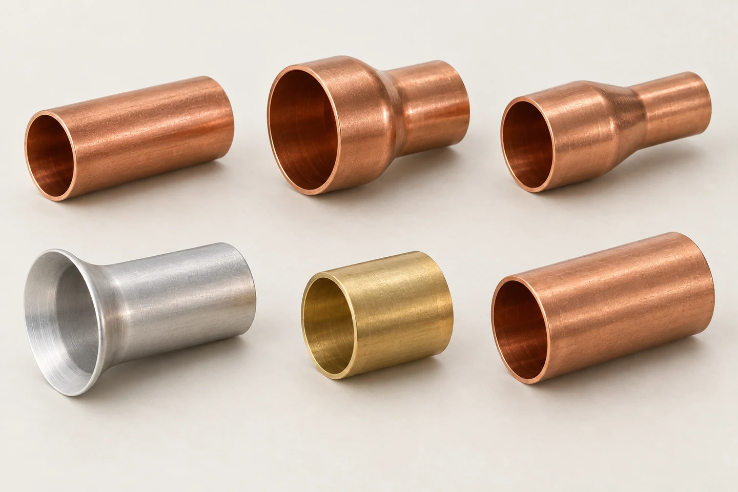
TUBE FAMILY / 직관·확관·축관·플레어와 슬리브

TUBE FAMILY / 직관·확관·축관·플레어와 슬리브

Structure.

부품 기능과 공급 상태를 정의합니다.

01 / FUNCTION & INTERFACE

슬리브는 형상과 접합을 함께 결정하는 부품입니다

외경이 맞는 것과 유체 연결부가 안정적인 것은 다른 판단입니다.

비철 파이프 슬리브는 상대 관을 안내하고 겹침 길이와 접합 간극을 만드는 연결 부품입니다. 냉동공조·열교환·유체 배관에서는 압력, 진동, 열팽창과 조립 하중을 함께 받습니다. 작은 성형 편차가 삽입 불량이나 누설 경로로 이어질 수 있습니다.

축관은 단면을 줄이고 확관은 소켓이나 플레어를 만듭니다. 최종 직경이 같더라도 공정 경로에 따라 벽두께, 경화와 잔류 변형은 달라집니다. 형상 도면에는 모재 상태와 접합 이후 요구까지 포함되어야 합니다.

검토의 시작점은 실제 기능입니다. 브레이징 소켓인지, 기계적 압입부인지, 씰을 지지하는 슬리브인지 먼저 구분합니다. 각 구조는 필요한 간극·표면·삽입 깊이와 검증 방식이 달라 하나의 만능 공차로 관리하기 어렵습니다.

위치 안내

상대 관 정렬·삽입 · 기준 축과 깊이

접합 계면

겹침·간극·표면 · 공정별 요구 구분

사용 하중

압력·진동·온도 · 조립체 검증

슬리브는 형상과 접합을 함께 결정하는 부품입니다 — 실무 판단 기준

검토 항목기술적 의미검증·관리 기준
위치 안내상대 관 정렬·삽입기준 축과 깊이
접합 계면겹침·간극·표면공정별 요구 구분
사용 하중압력·진동·온도조립체 검증

위치 안내

기술적 의미
상대 관 정렬·삽입

검증·관리 기준
기준 축과 깊이

접합 계면

기술적 의미
겹침·간극·표면

검증·관리 기준
공정별 요구 구분

사용 하중

기술적 의미
압력·진동·온도

검증·관리 기준
조립체 검증

02 / MATERIAL & TEMPER

구리·알루미늄·황동은 조질까지 구분합니다

같은 금속이라도 이전 가공과 열 이력이 성형 한계를 바꿉니다.

구리관의 연질·경질 상태와 알루미늄의 합금·열처리 상태는 확관 하중과 균열 경향에 영향을 줍니다. 입고 시 합금명만 확인하지 말고 공급 조질, 인장 특성, 경도와 치수 분포를 연결합니다. 황동 역시 합금 조성과 가공 이력에 따라 거동이 달라집니다.

C1100 관의 성형 한계는 관 치수와 재료 상태, 변형 국부화 및 변형 경로와 함께 평가합니다. 시험 방법과 시편 조건을 명확히 하고, 하나의 결과를 모든 구리 슬리브의 허용 확관률로 사용하지 않습니다. 다른 조질이나 두께에는 별도 확인이 필요합니다.

절단면의 가공 경화, 이음부 유무와 소재 편심도 관리 항목입니다. 초기 관의 벽두께 최소점이 확관 후 취약부가 될 수 있으므로 단면 방향과 길이 위치를 정해 측정합니다. 재료 교체는 최종 외경만 비교하는 변경으로 취급하지 않습니다.

등급·조질

변형 저항과 연성 · 성적서·경도·시험

초기 형상

벽두께 편심·원형도 · 위치별 측정

가공 이력

절단·인발·열처리 · 로트 추적

같은 금속이라도 이전 가공과 열 이력이 성형 한계를 바꿉니다.

실무 적용

열처리 후 외관이 같아도 강도·연성·잔류 상태는 달라질 수 있습니다. 공급 상태와 성형 직전 상태를 구분하여 승인 자료에 남깁니다.

구리·알루미늄·황동은 조질까지 구분합니다 — 실무 판단 기준

검토 항목기술적 의미검증·관리 기준
등급·조질변형 저항과 연성성적서·경도·시험
초기 형상벽두께 편심·원형도위치별 측정
가공 이력절단·인발·열처리로트 추적

등급·조질

기술적 의미
변형 저항과 연성

검증·관리 기준
성적서·경도·시험

초기 형상

기술적 의미
벽두께 편심·원형도

검증·관리 기준
위치별 측정

가공 이력

기술적 의미
절단·인발·열처리

검증·관리 기준
로트 추적

Materials.

축관과 확관의 변형 경로를 구분합니다.

03 / REDUCTION & FLOW

축관의 벽두께는 축 방향 재료 흐름과 연결됩니다

직경이 줄어든 만큼 벽이 반드시 두꺼워지는 것은 아닙니다.

축관 중 재료는 반경 방향으로 눌리면서 길이 방향으로도 이동합니다. 벽두께 증가량은 감소 직경뿐 아니라 축 방향 연신, 마찰, 공급 속도와 내부 지지에 좌우됩니다. 두꺼워진다는 일반 설명만으로 최소벽을 예측해서는 안 됩니다.

만드렐 없는 강관의 로터리 스웨이징에서는 마찰과 초기 두께가 재료 흐름과 최종 두께에 영향을 줄 수 있습니다. 재료와 변형 경로가 달라지면 응답도 달라지므로 해당 마찰계수나 변형량을 구리·알루미늄에 그대로 적용하지 않습니다.

금형 진입부, 교정부와 끝단을 나누어 두께·직경·표면 흔적을 측정합니다. 주름이나 내면 접힘은 외경 검사만으로 놓칠 수 있습니다. 내부 만드렐을 쓰는 경우에는 윤활, 간극, 인출성과 내면 손상까지 함께 검토합니다.

반경 압축

직경 감소 · 감소율과 단계

축 방향 흐름

연신·역류 · 길이·두께 동시 측정

마찰·이송

흐름과 표면 변화 · 윤활·속도 관리

실무 적용

공정 개발에서는 최종 직경뿐 아니라 길이 변화도 기록합니다. 길이와 두께가 함께 변하는 양상을 보면 불안정한 재료 흐름을 찾기 쉽습니다.

축관의 벽두께는 축 방향 재료 흐름과 연결됩니다 — 실무 판단 기준

검토 항목기술적 의미검증·관리 기준
반경 압축직경 감소감소율과 단계
축 방향 흐름연신·역류길이·두께 동시 측정
마찰·이송흐름과 표면 변화윤활·속도 관리
내부 지지내면 형상·접힘만드렐·단면 확인

반경 압축

기술적 의미
직경 감소

검증·관리 기준
감소율과 단계

축 방향 흐름

기술적 의미
연신·역류

검증·관리 기준
길이·두께 동시 측정

마찰·이송

기술적 의미
흐름과 표면 변화

검증·관리 기준
윤활·속도 관리

내부 지지

기술적 의미
내면 형상·접힘

검증·관리 기준
만드렐·단면 확인

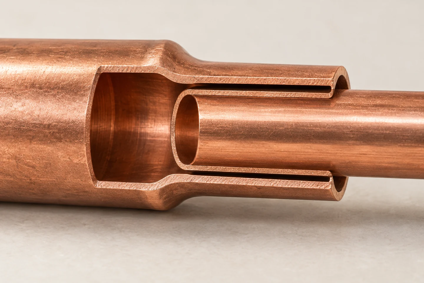
SOCKET INTERFACE / 겹침 연결부의 두 관벽과 환상 간극

SOCKET INTERFACE / 겹침 연결부의 두 관벽과 환상 간극

04 / EXPANSION & LOCALIZATION

확관 한계는 끝단의 국부 변형으로 결정됩니다

평균 확관률이 같아도 모서리·마찰·두께 편차가 균열을 바꿉니다.

확관에서는 둘레 방향 인장과 두께 감소가 함께 나타날 수 있습니다. 펀치 형상, 진입 각도와 마찰이 접촉 구간과 변형 분포를 바꾸므로 단순 직경비만으로 균열을 예측하기 어렵습니다. 끝단의 미세 버와 절단 손상은 국부 집중을 키울 수 있습니다.

플레어 시험은 관의 변형능을 조사하는 유용한 방법이지만 원뿔 각도·시험편 길이·끝단 상태를 함께 기록해야 합니다. ISO 8493과 링 확관 시험 ISO 8495는 서로 다른 시험 범위이며, 소형 박육 슬리브에 적용할 때에는 크기와 목적의 적합성을 먼저 확인합니다.

한 번에 큰 변형을 주는 공정과 여러 단계 공정은 누적 경화와 표면 상태가 다릅니다. 중간 열처리는 연성 회복뿐 아니라 산화·치수 변동을 만들 수 있으므로 후세척과 측정까지 공정 창에 포함합니다. 균열이 없다는 외관 판정만으로 남은 변형 여유를 보증하지 않습니다.

평균 확관률이 같아도 모서리·마찰·두께 편차가 균열을 바꿉니다.

확관 한계는 끝단의 국부 변형으로 결정됩니다 — 실무 판단 기준

검토 항목기술적 의미검증·관리 기준
확관 입력펀치·각도·스트로크공정별 고정 조건
국부 취약부끝단 버·최소벽성형 전 확대 검사
시험 범위드리프트·링 확관규격 적용성 확인
단계 성형경화·중간 열처리단계별 상태 추적

확관 입력

기술적 의미
펀치·각도·스트로크

검증·관리 기준
공정별 고정 조건

국부 취약부

기술적 의미
끝단 버·최소벽

검증·관리 기준
성형 전 확대 검사

시험 범위

기술적 의미
드리프트·링 확관

검증·관리 기준
규격 적용성 확인

단계 성형

기술적 의미
경화·중간 열처리

검증·관리 기준
단계별 상태 추적

3D · 축관·확관과 중공 단면

STRUCTURE & INTERFACE
ID SOLUTECH / 01
인터랙티브 3D를 준비하고 있습니다.
축관 형상

다이 분할과 공구 지지가 형상 안정성에 영향을 줍니다. 이 단계는 실제 변형률 해석이 아닙니다.

드래그·방향키: 회전 / + −: 확대·축소 / Home: 초기화축관·확관과 중공 단면

직경과 함께 재료의 흐름을 봅니다.

Precision.

간극을 만드는 형상과 표면을 관리합니다.

05 / ROUNDNESS & COAXIALITY

소켓의 원형도와 축 정렬이 간극을 만듭니다

두 지점에서 맞는 내경이 둘레 전체의 간극을 보장하지 않습니다.

타원 소켓에 원형 관을 넣으면 어떤 방향은 과도하게 좁고 다른 방향은 넓은 간극이 생깁니다. 내경 평균값보다 최대·최소 직경과 형상 편차가 중요할 수 있습니다. 측정 위치를 입구 한 단면에 한정하면 테이퍼와 깊이 방향 변형을 놓칩니다.

동축도와 삽입 깊이는 지그와 스토퍼 조건에도 영향을 받습니다. 삽입 중 관이 한쪽에 닿으면 공칭 간극을 만족해도 실제 브레이징 경로는 균일하지 않습니다. 외경·내경·축 관계를 도면 기준과 같은 좌표계에서 평가합니다.

플러그 게이지는 빠른 통과 판정에 유용하지만 결함 위치와 형상을 모두 설명하지는 못합니다. 개발에서는 형상 측정과 단면을 병행하여 게이지의 검출 범위를 정합니다. 얇은 관을 과하게 조여 측정 중에 원형도를 바꾸지 않도록 지지를 설계합니다.

둘레 형상

타원·국부 눌림 · 다방향·형상 측정

깊이 형상

테이퍼·목부 변형 · 다단면 내경

축 정렬

편심·경사 삽입 · 기준 축과 치구

실무 적용

소켓 입구·중앙·바닥의 측정값을 위치 지도에 남기면 공구 마모와 클램핑 영향이 구분됩니다. 합격 숫자 하나보다 형상 분포가 원인 분석에 유용합니다.

소켓의 원형도와 축 정렬이 간극을 만듭니다 — 실무 판단 기준

검토 항목기술적 의미검증·관리 기준
둘레 형상타원·국부 눌림다방향·형상 측정
깊이 형상테이퍼·목부 변형다단면 내경
축 정렬편심·경사 삽입기준 축과 치구
게이지통과 범위·검출 한계실측·단면 상관

둘레 형상

기술적 의미
타원·국부 눌림

검증·관리 기준
다방향·형상 측정

깊이 형상

기술적 의미
테이퍼·목부 변형

검증·관리 기준
다단면 내경

축 정렬

기술적 의미
편심·경사 삽입

검증·관리 기준
기준 축과 치구

게이지

기술적 의미
통과 범위·검출 한계

검증·관리 기준
실측·단면 상관

06 / SURFACE & CLEANLINESS

윤활과 세척은 성형·접합을 이어 주는 공정입니다

성형에 유리한 잔류막이 접합에는 불리할 수 있습니다.

윤활은 마찰과 표면 손상을 줄이지만 도포량과 분포가 일정하지 않으면 재료 흐름도 달라질 수 있습니다. 금형 자국과 늘어붙음이 생기면 윤활 조건, 공구 거칠기와 소재 표면을 함께 확인합니다. 단순히 오일을 더 바르는 조치로 모든 결함을 해결하지 않습니다.

브레이징 전에는 오일, 산화물과 입자 잔류가 젖음과 충전에 영향을 줄 수 있습니다. 세척제가 모재와 맞는지, 내부에 잔류하는지, 건조 뒤 재오염이 생기는지를 관리합니다. 외부가 깨끗해 보여도 긴 소켓 안쪽은 별도 확인이 필요합니다.

냉동공조 용도의 청정도 요구는 실제 유체와 시스템에 따라 달라집니다. 내면 입자·수분·잔류물 기준을 고객 요구에 맞춰 정하고 세척 뒤 포장까지 연결합니다. 브레이징 플럭스와 솔더링 플럭스는 용도와 온도 범위가 달라 임의 교체하지 않습니다.

윤활

마찰·흐름·표면 · 양·분포·교체 주기

세척

오일·입자·산화물 · 모재 적합성과 잔류

건조·보관

수분·재오염 · 밀봉·청정 취급

실무 적용

성형 직후와 접합 직전의 표면 상태를 각각 확인합니다. 중간 보관 시간과 포장재도 오염 원인 추적에 포함합니다.

윤활과 세척은 성형·접합을 이어 주는 공정입니다 — 실무 판단 기준

검토 항목기술적 의미검증·관리 기준
윤활마찰·흐름·표면양·분포·교체 주기
세척오일·입자·산화물모재 적합성과 잔류
건조·보관수분·재오염밀봉·청정 취급
접합 보조재플럭스·표면 준비공정 온도와 조합

윤활

기술적 의미
마찰·흐름·표면

검증·관리 기준
양·분포·교체 주기

세척

기술적 의미
오일·입자·산화물

검증·관리 기준
모재 적합성과 잔류

건조·보관

기술적 의미
수분·재오염

검증·관리 기준
밀봉·청정 취급

접합 보조재

기술적 의미
플럭스·표면 준비

검증·관리 기준
공정 온도와 조합

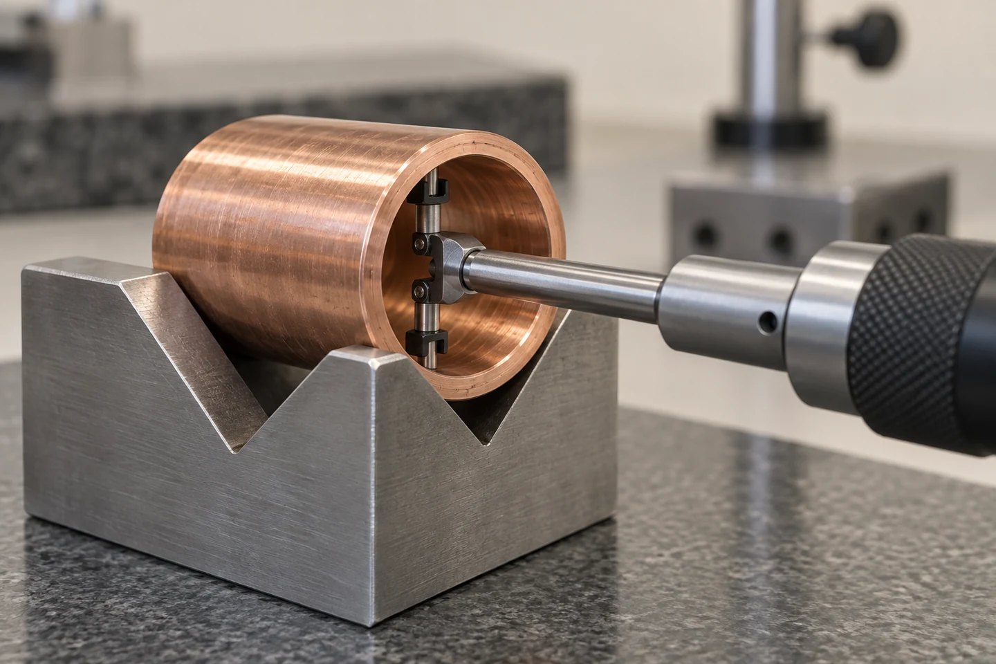
METROLOGY / 슬리브의 내경 측정

METROLOGY / 슬리브의 내경 측정

Motion.

열 이력과 최소벽을 연결합니다.

07 / BRAZING & HEAT HISTORY

상온 간극과 브레이징 후 재료 상태를 함께 봅니다

열은 접합재를 흐르게 하는 동시에 성형된 관의 상태도 바꿉니다.

브레이징은 적절한 간극과 젖는 표면을 따라 접합재가 충전되는 공정입니다. 간극은 상대재의 열팽창과 실제 가열 분포에 따라 상온과 달라질 수 있습니다. 특정 솔더링 간극 숫자를 다른 필러·금속 조합의 브레이징 기준으로 전용하지 않습니다.

구리관의 브레이징 열은 접합 주변을 연화시킬 수 있습니다. 브레이징된 관의 압력을 검토할 때는 연화된 상태를 고려합니다. 성형으로 얻은 경화가 접합 후에도 그대로 유지된다고 가정하면 내압과 피로 판단이 어긋날 수 있습니다.

소켓 깊이, 필러 배치, 가스 배출과 열 입력을 함께 확인합니다. 외부 필렛이 있어도 내부 충전을 증명하지는 못하므로 개발 단면과 적용 가능한 검사로 침투 분포를 확인합니다. 접합 이후 관의 변형과 내면 막힘도 기능 판정에 포함합니다.

고온 간극

열팽창·온도 차이 · 재료·실제 열 이력

겹침 길이

충전 경로·강도 · 삽입 깊이·단면

모재 연화

경화 상태 변화 · 열영향부 검토

열은 접합재를 흐르게 하는 동시에 성형된 관의 상태도 바꿉니다.

실무 적용

공정 비교에서는 최고 온도만 아니라 가열 시간과 위치별 차이를 기록합니다. 짧은 열 이력과 긴 열 이력이 같은 모재 상태를 남긴다고 가정하지 않습니다.

상온 간극과 브레이징 후 재료 상태를 함께 봅니다 — 실무 판단 기준

검토 항목기술적 의미검증·관리 기준
고온 간극열팽창·온도 차이재료·실제 열 이력
겹침 길이충전 경로·강도삽입 깊이·단면
모재 연화경화 상태 변화열영향부 검토
접합 결과침투·공극·막힘내부와 기능 검사

고온 간극

기술적 의미
열팽창·온도 차이

검증·관리 기준
재료·실제 열 이력

겹침 길이

기술적 의미
충전 경로·강도

검증·관리 기준
삽입 깊이·단면

모재 연화

기술적 의미
경화 상태 변화

검증·관리 기준
열영향부 검토

접합 결과

기술적 의미
침투·공극·막힘

검증·관리 기준
내부와 기능 검사

3D · 슬리브 끼움과 간극 검사

PROCESS & VALIDATION
ID SOLUTECH / 02
인터랙티브 3D를 준비하고 있습니다.
조립 간극

간극은 판독을 위해 확대했습니다. 실제 허용값은 재료·접합 공정·온도에 맞춰 정합니다.

드래그·방향키: 회전 / + −: 확대·축소 / Home: 초기화슬리브 끼움과 간극 검사
08 / STRAIN & MINIMUM WALL

변형률 계산을 최소벽 측정과 연결합니다

체적 보존은 유용하지만 국부 박육을 평균값으로 가릴 수 있습니다.

얇은 원관의 균일한 소성변형에서는 둘레·축·두께 방향 진변형률의 합을 거의 0으로 보는 1차 근사가 유용합니다. 축 방향 구속이 달라지면 같은 직경 증가에서도 두께 변화가 달라지는 이유를 설명합니다. 그러나 어깨부와 끝단의 국부 집중은 별도로 확인해야 합니다.

성형 전후 직경으로 둘레 변형률을 계산할 때에는 대응하는 재료 위치와 측정 직경의 정의를 고정합니다. 외경과 중간면 직경을 혼용하거나 다른 위치를 비교하면 계산이 흐려집니다. 얇은 관의 평균 예측은 실제 단면 두께 지도와 대조합니다.

설계 판정에서는 최소벽 위치가 압력과 굽힘의 최대 응력 위치에 겹치는지 확인합니다. 경화가 강도를 올릴 수 있다는 설명이 박육과 균열 민감도를 상쇄한다는 뜻은 아닙니다. 해석 모델은 마찰·재료 곡선·경계조건을 검증된 시편으로 보정합니다.

체적 보존은 유용하지만 국부 박육을 평균값으로 가릴 수 있습니다.

Dm은 대응 위치의 관 중간면 직경, t는 벽두께이며 0과 f는 성형 전후입니다. εθ·εz·εt는 둘레·축·두께 방향 진변형률입니다. 얇은 원관의 균일 변형·소성 비압축성 근사이며 국부 넥킹, 전이부, 손상과 스프링백을 직접 예측하지 않습니다.

실무 적용

계산은 공정 후보를 좁히는 도구로 사용합니다. 최종 내압·피로·접합 판정은 실제 성형·접합 상태의 검증으로 결정합니다.

변형률 계산을 최소벽 측정과 연결합니다 — 실무 판단 기준

검토 항목기술적 의미검증·관리 기준
둘레 변형대응 직경의 로그 비측정 위치·정의 고정
축 변형길이 방향 재료 흐름길이 변화 추적
두께 변화체적 보존 근사단면 최소벽 대조
국부 한계어깨·끝단 집중해석과 실측 연결

둘레 변형

기술적 의미
대응 직경의 로그 비

검증·관리 기준
측정 위치·정의 고정

축 변형

기술적 의미
길이 방향 재료 흐름

검증·관리 기준
길이 변화 추적

두께 변화

기술적 의미
체적 보존 근사

검증·관리 기준
단면 최소벽 대조

국부 한계

기술적 의미
어깨·끝단 집중

검증·관리 기준
해석과 실측 연결

최소벽과 실제 간극이 연결부의 성능을 좌우합니다.

Interface.

측정과 기능 시험의 범위를 구분합니다.

09 / METROLOGY & DEFECTS

측정 위치를 정하면 성형 결함의 원인이 보입니다

직경·최소벽·표면 결함을 같은 좌표에 기록합니다.

입구, 어깨 전후, 소켓 중앙과 비성형부를 구분해 외경·내경·벽두께를 측정합니다. 최대·최소값만 남기기보다 방향과 위치를 함께 남기면 초기 소재 편심과 금형 정렬 문제를 구별하는 데 도움이 됩니다. 비파괴 두께 측정은 곡률과 얇은 벽에서의 적용성을 먼저 확인합니다.

절단 단면은 준비 과정에서 버나 눌림을 만들 수 있습니다. 시편 지지, 절단 방향과 연마 방법을 고정하고 의심 흔적은 다른 단면으로 확인합니다. 표면 균열 검사는 재질·청정도·결함 크기에 맞는 방법과 검출 한계를 정합니다.

ISO 8495의 링 확관은 표면과 벽 내부의 결함을 드러내고 변형능을 평가하는 목적이 있습니다. 다만 정해진 크기 범위를 벗어난 작은 슬리브에 표준 적합성을 주장하지 않습니다. 생산품 자체의 치수·균열·누설 기준은 별도 승인 문서로 정합니다.

직경·최소벽·표면 결함을 같은 좌표에 기록합니다.

실무 적용

개발 단면은 양호 시편과 불량 시편을 같은 방법으로 비교합니다. 검사 과정이 만든 흔적을 공정 결함으로 오인하지 않도록 합니다.

측정 위치를 정하면 성형 결함의 원인이 보입니다 — 실무 판단 기준

검토 항목기술적 의미검증·관리 기준
치수 지도입구·어깨·중앙·모재위치·방향 기록
단면 품질절단·연마 유발 흔적준비법 고정
균열 검출개구·크기·위치방법 적합성과 한계
합격 판정기능별 허용 범위도면·검사 사양

치수 지도

기술적 의미
입구·어깨·중앙·모재

검증·관리 기준
위치·방향 기록

단면 품질

기술적 의미
절단·연마 유발 흔적

검증·관리 기준
준비법 고정

균열 검출

기술적 의미
개구·크기·위치

검증·관리 기준
방법 적합성과 한계

합격 판정

기술적 의미
기능별 허용 범위

검증·관리 기준
도면·검사 사양

10 / LEAK & PRESSURE

누설과 압력 강도는 서로 다른 검증입니다

지금 새지 않는 연결부가 반복 압력에도 견디는 것은 아닙니다.

누설 시험은 정의한 압력 차와 검출 한계에서 관통 경로를 찾습니다. 내압 또는 파열 시험은 압력 하중에 대한 구조적 저항을 평가합니다. 두 시험의 목적과 결과를 구분하고 시험 유체, 온도, 유지 시간과 지그 밀봉의 영향을 기록합니다.

추적가스를 사용할 때에는 ISO 20485의 공개 범위처럼 가스와 검출기에 맞는 방법을 선택합니다. 누설률 단위, 기준 압력과 배경·응답 시간을 고정해야 비교가 가능합니다. 시험 장비의 표시값이 실제 부품 누설인지 치구 누설인지 분리합니다.

ISO 19879는 유압 금속 연결부 시험을 다루며 모든 냉매 시스템의 자동 승인 기준은 아닙니다. 대상 제품에 필요한 시험을 선택하고 실제 유체·압력·온도와 연결합니다. 검출되지 않음은 사용한 방법의 검출 한계 아래라는 뜻이지 절대 누설 0의 증거는 아닙니다.

누설

관통 경로·검출 한계 · 누설률·기준 조건

내압

영구 변형·건전성 · 압력·시간·온도

파열

최종 파괴와 위치 · 파단 경로 기록

실무 적용

압력 시험 후에는 치수와 표면 상태도 재확인합니다. 통과·실패만 남기지 않고 변형과 파괴 위치를 설계 검토로 돌려보냅니다.

누설과 압력 강도는 서로 다른 검증입니다 — 실무 판단 기준

검토 항목기술적 의미검증·관리 기준
누설관통 경로·검출 한계누설률·기준 조건
내압영구 변형·건전성압력·시간·온도
파열최종 파괴와 위치파단 경로 기록
측정 신뢰성치구·배경·응답기준 누설·장비 확인

누설

기술적 의미
관통 경로·검출 한계

검증·관리 기준
누설률·기준 조건

내압

기술적 의미
영구 변형·건전성

검증·관리 기준
압력·시간·온도

파열

기술적 의미
최종 파괴와 위치

검증·관리 기준
파단 경로 기록

측정 신뢰성

기술적 의미
치구·배경·응답

검증·관리 기준
기준 누설·장비 확인

Validation.

실제 설치 내구에서 양산 승인으로 이어갑니다.

11 / VIBRATION & THERMAL SERVICE

관 지지와 강성 변화가 연결부 피로를 바꿉니다

슬리브 단독 시험과 실제 배관의 움직임을 연결해야 합니다.

소켓 끝이나 축관 어깨는 단면 강성이 달라지는 위치입니다. 주변 배관이 진동하면 굽힘이 이곳에 집중될 수 있으므로 곡률·전이 길이와 지지 위치를 검토합니다. 벽두께가 충분해도 날카로운 형상 변화가 피로의 약점이 될 수 있습니다.

온도에 따른 배관 길이 변화는 연결부에 추가 구속력을 만들 수 있습니다. 열팽창을 흡수할 수 있는 배관 형상이 필요합니다. 슬리브의 재료만 바꾸기 전에 전체 배관의 고정점과 움직임을 확인합니다.

정적 파열, 진동 반복과 압력 반복은 고장 경로가 다르므로 따로 평가합니다. 실제 성형·브레이징 상태와 설치 지지를 포함해 시험을 구성하고 종료 후 누설·균열·잔존 성능을 함께 확인합니다.

형상 전이

강성·응력 집중 · 어깨 반경·길이

배관 지지

굽힘·공진·구속 · 실제 장착 반영

온도 변화

열팽창·추가 하중 · 고정점과 이동

슬리브 단독 시험과 실제 배관의 움직임을 연결해야 합니다.

실무 적용

누설이 시작한 위치와 균열의 출발 위치를 구분해 기록합니다. 외부에서 보이는 젖음 위치가 실제 손상 시작점과 다를 수 있습니다.

관 지지와 강성 변화가 연결부 피로를 바꿉니다 — 실무 판단 기준

검토 항목기술적 의미검증·관리 기준
형상 전이강성·응력 집중어깨 반경·길이
배관 지지굽힘·공진·구속실제 장착 반영
온도 변화열팽창·추가 하중고정점과 이동
내구 후균열·누설·잔존 강도초기와 비교

형상 전이

기술적 의미
강성·응력 집중

검증·관리 기준
어깨 반경·길이

배관 지지

기술적 의미
굽힘·공진·구속

검증·관리 기준
실제 장착 반영

온도 변화

기술적 의미
열팽창·추가 하중

검증·관리 기준
고정점과 이동

내구 후

기술적 의미
균열·누설·잔존 강도

검증·관리 기준
초기와 비교

12 / PRODUCTION RELEASE

성형·접합·검사를 하나의 승인 흐름으로 묶습니다

완성 치수뿐 아니라 그 치수를 만든 조건을 재현합니다.

양산 사양에는 소재·조질, 초기 두께, 절단·버 처리, 금형과 윤활, 단계별 직경·최소벽 기준을 포함합니다. 접합하는 경우에는 세척, 삽입 깊이, 필러와 열 이력까지 연결합니다. 최종 검사만 강화하는 것보다 변동이 생기는 위치를 관리하는 편이 효과적입니다.

공구 수명과 공급 로트 변경 시 두께 지도·원형도·성형력의 변화를 비교합니다. 소재·열처리·윤활·브레이징 조건 변경은 영향받는 특성과 재검증 범위를 문서화합니다. 승인된 시제품과 실제 생산품을 추적할 수 있도록 기록 체계를 구성합니다.

아이디솔루텍과 제작 검토를 진행할 때에는 관의 합금·조질, 상대 관 도면, 최소벽·간극 요구, 접합 방식, 사용 유체·압력·온도와 수량을 제공해 주세요. 성형 경로와 검사 계획을 함께 정하면 삽입성·접합성·내구를 균형 있게 검토할 수 있습니다.

재료

합금·조질·초기 두께 · 입고와 로트

성형

금형·단계·윤활 · 힘·치수·최소벽

접합

세척·간극·열 이력 · 충전과 재료 상태

실무 적용

기존 불량은 누설 위치 사진뿐 아니라 성형 전후 치수와 접합 조건을 함께 비교합니다. 성형과 브레이징 중 어느 단계에서 취약부가 생겼는지 분리할 수 있습니다.

성형·접합·검사를 하나의 승인 흐름으로 묶습니다 — 실무 판단 기준

검토 항목기술적 의미검증·관리 기준
재료합금·조질·초기 두께입고와 로트
성형금형·단계·윤활힘·치수·최소벽
접합세척·간극·열 이력충전과 재료 상태
승인누설·압력·진동·변경증거와 추적

재료

기술적 의미
합금·조질·초기 두께

검증·관리 기준
입고와 로트

성형

기술적 의미
금형·단계·윤활

검증·관리 기준
힘·치수·최소벽

접합

기술적 의미
세척·간극·열 이력

검증·관리 기준
충전과 재료 상태

승인

기술적 의미
누설·압력·진동·변경

검증·관리 기준
증거와 추적

성형과 접합의 증거를 하나로 연결합니다.

Start a
Project.

관·상대재 도면, 합금·조질, 최소벽·간극과 유체·압력·온도 조건을 공유해 주세요. 성형 경로와 접합·검사 계획을 함께 검토합니다.

Share tube and mating-part drawings, alloy, temper, minimum wall, clearance, fluid, pressure and temperature to define forming, joining and inspection.

개발 상담 · Contact

기술 협의 · Engineering Consultation
도면과 사양을 기준으로 소재·가공·표면처리,
주요 품질 항목과 공급 조건을 함께 검토합니다.


We review drawings and specifications to define materials, manufacturing methods, surface finishes, key quality requirements, and supply conditions.

개발 의뢰하기 · Development Inquiry

    도면 및 기술자료
    Drawings & Technical Documents

    도면 번호와 개정 이력이 표시된 2D·3D 도면을 첨부해 주세요.
    사양서와 검사 기준도 함께 전달할 수 있습니다.
    Attach your 2D or 3D drawings with their drawing numbers and revisions.
    Include specifications and inspection criteria as needed.

    파일을 이곳에 놓아주세요Drag & drop your files here

    선택된 파일 없음 / No files attached

    최대 5개 · 파일당 5MB · 총 15MB / Up to 5 files · 5MB each · 15MB total
    PDF · DWG · DXF · STEP/STP · IGS/IGES · JPG · PNG · ZIP

    * 필수 입력 / Required fields

    TUBE SLEEVE FORMING

    확관 구리관·축관 알루미늄관·플랜지 슬리브

    Tube & Sleeve
    Forming Engineering

    Connect diameter, wall, surface and heat history to review forming and joining as one process.

    Swaging · Expansion · Wall thickness · Joint integrity

    ENGLISH EDITION

    Tube & Sleeve
    Forming Precision

    From reduction, expansion and minimum wall to brazing and leak validation

    Precision geometry. Reliable connections.

    Sleeve quality cannot be reduced to one outside diameter. Minimum wall, roundness, surface and worked condition created by forming determine joining clearance and post-braze behavior.

    This article connects tube-forming routes, material condition and applicable test conditions with processing, metrology, pressure and durability.

    TUBE FAMILY / 직관·확관·축관·플레어와 슬리브

    TUBE FAMILY / Straight, expanded, reduced and flared ends with sleeves

    Structure.

    Define component function and supply condition.

    01 / FUNCTION & INTERFACE

    A Sleeve Defines Both Geometry and Joining

    Correct outside diameter does not establish a reliable fluid connection.

    A nonferrous tube sleeve guides the mating tube and establishes overlap and joining clearance. HVAC, heat-exchanger and fluid systems impose pressure, vibration, expansion and assembly loads. Small forming variations can become insertion defects or leakage paths.

    Reduction decreases the section; expansion creates a socket or flare. Identical final diameter does not establish identical wall thickness, hardening or residual deformation. The drawing needs material condition and requirements after joining as well as geometry.

    Begin with function: a brazed socket, interference joint and seal-support sleeve need different clearances, surfaces, insertion depths and verification. A universal tolerance cannot adequately represent all three.

    Guidance

    Alignment and insertion. Datum axis and depth

    Joining interface

    Overlap, gap and surface. Process-specific requirements

    Service loads

    Pressure, vibration and temperature. Assembly validation

    A Sleeve Defines Both Geometry and Joining — Review Criteria

    Review itemEngineering significanceVerification or control
    GuidanceAlignment and insertionDatum axis and depth
    Joining interfaceOverlap, gap and surfaceProcess-specific requirements
    Service loadsPressure, vibration and temperatureAssembly validation

    Guidance

    Engineering significance
    Alignment and insertion

    Verification or control
    Datum axis and depth

    Joining interface

    Engineering significance
    Overlap, gap and surface

    Verification or control
    Process-specific requirements

    Service loads

    Engineering significance
    Pressure, vibration and temperature

    Verification or control
    Assembly validation

    02 / MATERIAL & TEMPER

    Distinguish Copper, Aluminum and Brass by Temper

    Prior working and heating change formability within the same metal family.

    Copper temper and aluminum alloy/heat treatment affect expansion force and cracking. At receipt, connect the alloy identity with temper, tensile behavior, hardness and dimensional distribution. Brass response also depends on composition and processing history.

    Evaluate C1100 tube forming limits together with dimensions, material condition, strain localization and strain path. Define test methods and specimen conditions rather than treating one result as a universal expansion allowance for copper sleeves. Different tempers and thicknesses require confirmation.

    Cut-edge work hardening, seams and incoming eccentricity also matter. A minimum-wall location in the original tube can become a weak region after expansion. Define axial and circumferential measurement locations, and do not treat material substitution as an outside-diameter-only change.

    Grade and temper

    Flow resistance and ductility. Certificates, hardness and tests

    Initial geometry

    Wall eccentricity and roundness. Position-specific measurement

    Processing history

    Cutting, drawing and heat treatment. Lot traceability

    Prior working and heating change formability within the same metal family.

    Application review

    Similar appearance after heat treatment does not establish identical strength or ductility. Record both supply condition and condition immediately before forming.

    Distinguish Copper, Aluminum and Brass by Temper — Review Criteria

    Review itemEngineering significanceVerification or control
    Grade and temperFlow resistance and ductilityCertificates, hardness and tests
    Initial geometryWall eccentricity and roundnessPosition-specific measurement
    Processing historyCutting, drawing and heat treatmentLot traceability

    Grade and temper

    Engineering significance
    Flow resistance and ductility

    Verification or control
    Certificates, hardness and tests

    Initial geometry

    Engineering significance
    Wall eccentricity and roundness

    Verification or control
    Position-specific measurement

    Processing history

    Engineering significance
    Cutting, drawing and heat treatment

    Verification or control
    Lot traceability

    Materials.

    Distinguish reduction and expansion strain paths.

    03 / REDUCTION & FLOW

    Wall Thickness in Reduction Follows Axial Material Flow

    Diameter reduction does not uniquely determine wall thickening.

    During reduction, radial compression is accompanied by axial flow. Wall thickening depends on elongation, friction, feed and internal support as well as diameter change. A general expectation of thickening is insufficient to predict minimum wall.

    In rotary swaging of mandrel-free steel tubes, friction and initial thickness can influence material flow and final wall. Material and strain-path changes alter the response, so do not transfer those friction coefficients or strains directly to copper and aluminum.

    Measure thickness, diameter and surface condition at entry transitions, sizing regions and ends. Outside diameter can conceal internal folds. With a mandrel, also review lubrication, clearance, removal and inner-surface damage.

    Radial compression

    Diameter reduction. Reduction and stages

    Axial flow

    Elongation and backward flow. Measure length and wall together

    Friction and feed

    Flow and surface condition. Control lubricant and feed

    Application review

    Record length change along with final diameter during development. Their combined behavior helps reveal unstable flow.

    Wall Thickness in Reduction Follows Axial Material Flow — Review Criteria

    Review itemEngineering significanceVerification or control
    Radial compressionDiameter reductionReduction and stages
    Axial flowElongation and backward flowMeasure length and wall together
    Friction and feedFlow and surface conditionControl lubricant and feed
    Internal supportBore shape and foldsMandrel and section review

    Radial compression

    Engineering significance
    Diameter reduction

    Verification or control
    Reduction and stages

    Axial flow

    Engineering significance
    Elongation and backward flow

    Verification or control
    Measure length and wall together

    Friction and feed

    Engineering significance
    Flow and surface condition

    Verification or control
    Control lubricant and feed

    Internal support

    Engineering significance
    Bore shape and folds

    Verification or control
    Mandrel and section review

    SOCKET INTERFACE / 겹침 연결부의 두 관벽과 환상 간극

    SOCKET INTERFACE / Tube walls and annular overlap clearance

    04 / EXPANSION & LOCALIZATION

    Expansion Limits Are Governed by Local Strain

    Equal average expansion can produce different edge strain and cracking.

    Expansion can combine circumferential tension with wall thinning. Punch geometry, entry angle and friction alter contact and strain distribution, so diameter ratio alone cannot predict cracking. Small burrs and cutting damage can intensify local strain.

    Flaring tests are useful for investigating tube deformability, but cone angle, specimen length and edge condition must be recorded. ISO 8493 and the ring-expanding method ISO 8495 have different scopes. Confirm size and purpose before applying them to a small thin-wall sleeve.

    Single-step and multi-step routes create different hardening and surface histories. Intermediate heat treatment may restore ductility while also changing oxidation and dimensions; include cleaning and remeasurement in the process window. Absence of visible cracks does not establish remaining forming reserve.

    Equal average expansion can produce different edge strain and cracking.

    Expansion Limits Are Governed by Local Strain — Review Criteria

    Review itemEngineering significanceVerification or control
    Expansion inputsPunch, angle and strokeFixed process conditions
    Local weak regionsEdge burr and minimum wallMagnified preforming inspection
    Test scopeDrift and ring expansionCheck applicability
    Staged formingHardening and intermediate heatingTrace condition by stage

    Expansion inputs

    Engineering significance
    Punch, angle and stroke

    Verification or control
    Fixed process conditions

    Local weak regions

    Engineering significance
    Edge burr and minimum wall

    Verification or control
    Magnified preforming inspection

    Test scope

    Engineering significance
    Drift and ring expansion

    Verification or control
    Check applicability

    Staged forming

    Engineering significance
    Hardening and intermediate heating

    Verification or control
    Trace condition by stage

    3D · Tube reduction, expansion and hollow section

    STRUCTURE & INTERFACE
    ID SOLUTECH / 01
    Preparing interactive 3D.
    Reduced end

    Die segmentation and support influence geometry; these stages are not a strain analysis.

    Drag / arrow keys: rotate · + −: zoom · Home: resetTube reduction, expansion and hollow section

    Follow material flow as well as diameter.

    Precision.

    Control geometry and surfaces that establish clearance.

    05 / ROUNDNESS & COAXIALITY

    Socket Roundness and Alignment Establish the Gap

    A two-point bore reading does not establish circumferential clearance.

    A round tube in an oval socket produces tight regions and wide regions. Maximum/minimum diameters and form error may be more important than mean bore size. Measuring only at the mouth can miss taper and deeper distortion.

    Coaxiality and insertion depth also depend on fixtures and stops. One-sided contact can disrupt the actual brazing path despite compliant nominal dimensions. Evaluate diameters and axis relationships in the drawing datum system.

    Plug gauges provide efficient acceptance checks but do not characterize every shape defect. Correlate gauging with form measurement and sections during development. Support thin tubing without clamping it into an artificial round shape.

    Circumferential form

    Ovality and local dents. Multiple directions and form measurement

    Axial form

    Taper and neck distortion. Several bore sections

    Axis alignment

    Offset and tilted insertion. Datums and fixtures

    Application review

    Map measurements at mouth, middle and socket base to distinguish tool wear from clamping effects. Shape distribution is more diagnostic than one passing value.

    Socket Roundness and Alignment Establish the Gap — Review Criteria

    Review itemEngineering significanceVerification or control
    Circumferential formOvality and local dentsMultiple directions and form measurement
    Axial formTaper and neck distortionSeveral bore sections
    Axis alignmentOffset and tilted insertionDatums and fixtures
    GaugingAcceptance and detection limitsCorrelation with measurements and sections

    Circumferential form

    Engineering significance
    Ovality and local dents

    Verification or control
    Multiple directions and form measurement

    Axial form

    Engineering significance
    Taper and neck distortion

    Verification or control
    Several bore sections

    Axis alignment

    Engineering significance
    Offset and tilted insertion

    Verification or control
    Datums and fixtures

    Gauging

    Engineering significance
    Acceptance and detection limits

    Verification or control
    Correlation with measurements and sections

    06 / SURFACE & CLEANLINESS

    Lubrication and Cleaning Connect Forming with Joining

    A film useful for forming can obstruct later joining.

    Lubrication reduces friction and surface damage, but variable coverage also changes flow. Investigate lubricant, tool roughness and material surface together when galling or scoring appears. Adding more oil is not a universal corrective action.

    Before brazing, oil, oxide and particles can affect wetting and filling. Control cleaner compatibility, internal residue, drying and recontamination. A clean exterior does not establish cleanliness inside a long socket.

    HVAC cleanliness requirements depend on fluid and system. Define internal particle, moisture and residue criteria from the customer specification and connect cleaning with packaging. Brazing and soldering fluxes differ in service range and should not be substituted arbitrarily.

    Lubrication

    Friction, flow and surface. Quantity, coverage and replacement

    Cleaning

    Oil, particles and oxide. Compatibility and residue

    Drying and storage

    Moisture and recontamination. Protected clean handling

    Application review

    Check surfaces after forming and again before joining. Include storage time and packaging in contamination traceability.

    Lubrication and Cleaning Connect Forming with Joining — Review Criteria

    Review itemEngineering significanceVerification or control
    LubricationFriction, flow and surfaceQuantity, coverage and replacement
    CleaningOil, particles and oxideCompatibility and residue
    Drying and storageMoisture and recontaminationProtected clean handling
    Joining aidsFlux and surface preparationTemperature and material pairing

    Lubrication

    Engineering significance
    Friction, flow and surface

    Verification or control
    Quantity, coverage and replacement

    Cleaning

    Engineering significance
    Oil, particles and oxide

    Verification or control
    Compatibility and residue

    Drying and storage

    Engineering significance
    Moisture and recontamination

    Verification or control
    Protected clean handling

    Joining aids

    Engineering significance
    Flux and surface preparation

    Verification or control
    Temperature and material pairing

    METROLOGY / 슬리브의 내경 측정

    METROLOGY / Bore measurement of a tube sleeve

    Motion.

    Connect thermal history with minimum wall.

    07 / BRAZING & HEAT HISTORY

    Review Assembly Clearance and Post-Braze Material Condition

    Heat moves filler while changing the formed tube itself.

    Brazing relies on filler flow along wettable surfaces with suitable clearance. Differential expansion and heating distribution can change the gap from its room-temperature value. A soldering-clearance number is not a universal brazing specification for another filler and metal combination.

    Brazing heat can soften copper near the joint. Consider the annealed condition when evaluating pressure capacity of brazed tubing. Assuming all forming-induced hardening survives joining can misrepresent pressure and fatigue behavior.

    Review socket depth, filler placement, venting and heat input together. An external fillet does not prove internal filling; establish penetration distribution through development sections and suitable inspection. Include post-braze distortion and bore obstruction in functional acceptance.

    Hot clearance

    Expansion and temperature difference. Materials and actual thermal history

    Overlap

    Filling path and strength. Insertion depth and sections

    Substrate softening

    Change of worked condition. Heat-affected-region review

    Heat moves filler while changing the formed tube itself.

    Application review

    Compare heating duration and spatial variation as well as peak temperature. Different thermal histories need not leave identical substrate condition.

    Review Assembly Clearance and Post-Braze Material Condition — Review Criteria

    Review itemEngineering significanceVerification or control
    Hot clearanceExpansion and temperature differenceMaterials and actual thermal history
    OverlapFilling path and strengthInsertion depth and sections
    Substrate softeningChange of worked conditionHeat-affected-region review
    Joint resultPenetration, voids and blockageInternal and functional inspection

    Hot clearance

    Engineering significance
    Expansion and temperature difference

    Verification or control
    Materials and actual thermal history

    Overlap

    Engineering significance
    Filling path and strength

    Verification or control
    Insertion depth and sections

    Substrate softening

    Engineering significance
    Change of worked condition

    Verification or control
    Heat-affected-region review

    Joint result

    Engineering significance
    Penetration, voids and blockage

    Verification or control
    Internal and functional inspection

    3D · Sleeve fit and clearance inspection

    PROCESS & VALIDATION
    ID SOLUTECH / 02
    Preparing interactive 3D.
    Assembly clearance

    The gap is enlarged for legibility. Specify actual limits for materials, joining process and temperature.

    Drag / arrow keys: rotate · + −: zoom · Home: resetSleeve fit and clearance inspection
    08 / STRAIN & MINIMUM WALL

    Connect Strain Calculation with Minimum-Wall Measurement

    Volume conservation is useful but averages can conceal local thinning.

    For approximately uniform plastic deformation of a thin circular tube, near-zero sum of hoop, axial and thickness true strains is a useful first approximation. It explains why axial constraint changes thickness at the same diameter expansion. Shoulder and edge localization still require separate examination.

    When deriving hoop strain from diameters, fix the corresponding material position and diameter definition. Mixing outside and midsurface diameters or different axial positions weakens the comparison. Compare average estimates with a measured wall-thickness map.

    Determine whether minimum wall coincides with high pressure or bending stress. Increased strength from work hardening does not automatically offset thinning or cracking sensitivity. Calibrate material curves, friction and boundary conditions against representative specimens.

    Volume conservation is useful but averages can conceal local thinning.

    Dm is midsurface diameter at corresponding material locations and t is wall thickness; 0 and f denote initial and final states. εθ, εz and εt are hoop, axial and thickness true strains. This uniform thin-tube, plastic-incompressibility approximation does not directly predict local necking, transitions, damage or springback.

    Application review

    Use calculation to narrow candidate processes. Determine final pressure, fatigue and joint acceptance on the formed and joined condition.

    Connect Strain Calculation with Minimum-Wall Measurement — Review Criteria

    Review itemEngineering significanceVerification or control
    Hoop strainLogarithmic ratio of matched diametersFixed position and definition
    Axial strainLongitudinal material flowTrack length change
    Thickness changeVolume-conservation approximationCompare section minimum wall
    Local limitsShoulder and edge concentrationConnect modeling and measurement

    Hoop strain

    Engineering significance
    Logarithmic ratio of matched diameters

    Verification or control
    Fixed position and definition

    Axial strain

    Engineering significance
    Longitudinal material flow

    Verification or control
    Track length change

    Thickness change

    Engineering significance
    Volume-conservation approximation

    Verification or control
    Compare section minimum wall

    Local limits

    Engineering significance
    Shoulder and edge concentration

    Verification or control
    Connect modeling and measurement

    Minimum wall and actual clearance govern joint behavior.

    Interface.

    Define metrology and functional-test scopes.

    09 / METROLOGY & DEFECTS

    Defined Measurement Locations Reveal Forming Defects

    Record diameter, minimum wall and surface features in one coordinate system.

    Measure outside diameter, bore and wall at the mouth, around the shoulder, socket middle and unformed region. Position and orientation help distinguish incoming eccentricity from tool misalignment. Qualify nondestructive thickness methods for curvature and thin walls.

    Section preparation can create burrs or deformation. Fix support, cutting direction and polishing, then corroborate doubtful features using other sections. Choose surface-crack methods and detection capability for the material, cleanliness and defect size.

    ISO 8495 ring expansion aims to reveal surface and wall defects and assess plastic deformability. Do not claim standard conformance for small sleeves outside its dimensional scope. Product-specific dimensional, crack and leakage limits require separate approval.

    Record diameter, minimum wall and surface features in one coordinate system.

    Application review

    Prepare sound and failed specimens consistently. Avoid misclassifying examination artifacts as forming defects.

    Defined Measurement Locations Reveal Forming Defects — Review Criteria

    Review itemEngineering significanceVerification or control
    Dimensional mapMouth, shoulder, middle and parent tubePosition and orientation
    Section qualityPreparation-induced featuresControlled preparation
    Crack detectionOpening, size and positionMethod suitability and limits
    AcceptanceFunction-specific limitsDrawing and inspection specification

    Dimensional map

    Engineering significance
    Mouth, shoulder, middle and parent tube

    Verification or control
    Position and orientation

    Section quality

    Engineering significance
    Preparation-induced features

    Verification or control
    Controlled preparation

    Crack detection

    Engineering significance
    Opening, size and position

    Verification or control
    Method suitability and limits

    Acceptance

    Engineering significance
    Function-specific limits

    Verification or control
    Drawing and inspection specification

    10 / LEAK & PRESSURE

    Leak Tightness and Pressure Strength Are Different Tests

    A leak-tight joint today is not automatically durable under pressure cycling.

    Leak testing seeks through-paths under a defined pressure difference and detection limit. Proof or burst testing evaluates structural resistance to pressure. Separate their purposes and record fluid, temperature, duration and fixture-seal effects.

    For tracer gas, select a method appropriate to the gas and detector within the published scope of ISO 20485. Fix leak-rate units, reference conditions, background and response time. Distinguish fixture leakage from leakage in the part.

    ISO 19879 addresses hydraulic metallic connections rather than automatic approval of every refrigerant system. Select tests for the product and relate them to actual fluid, pressure and temperature. No detected leak means below the method capability, not proof of absolute zero leakage.

    Leakage

    Through-paths and detection limit. Rate and reference conditions

    Proof pressure

    Permanent deformation and integrity. Pressure, duration and temperature

    Burst

    Ultimate failure and location. Record fracture path

    Application review

    Recheck dimensions and surfaces after pressure testing. Feed deformation and failure location back to design rather than recording only pass or fail.

    Leak Tightness and Pressure Strength Are Different Tests — Review Criteria

    Review itemEngineering significanceVerification or control
    LeakageThrough-paths and detection limitRate and reference conditions
    Proof pressurePermanent deformation and integrityPressure, duration and temperature
    BurstUltimate failure and locationRecord fracture path
    Measurement reliabilityFixture, background and responseReference leak and instrument check

    Leakage

    Engineering significance
    Through-paths and detection limit

    Verification or control
    Rate and reference conditions

    Proof pressure

    Engineering significance
    Permanent deformation and integrity

    Verification or control
    Pressure, duration and temperature

    Burst

    Engineering significance
    Ultimate failure and location

    Verification or control
    Record fracture path

    Measurement reliability

    Engineering significance
    Fixture, background and response

    Verification or control
    Reference leak and instrument check

    Validation.

    Connect installed durability with production approval.

    11 / VIBRATION & THERMAL SERVICE

    Tube Support and Stiffness Transitions Change Fatigue

    Connect sleeve tests with movement in the installed piping.

    Socket ends and reduced shoulders are stiffness transitions. Vibration of adjacent piping can concentrate bending there; review radius, transition length and support position. Adequate nominal wall does not remove fatigue sensitivity from abrupt geometry.

    Thermal length changes can add restraint loads to the connection. Provide a piping configuration that accommodates expansion. Review anchors and movement across the piping system before changing only the sleeve material.

    Assess static burst, vibration cycling and pressure cycling separately because they exercise different failure paths. Test the actual formed and brazed condition with representative support, then examine leakage, cracking and retained performance.

    Shape transition

    Stiffness and stress concentration. Shoulder radius and length

    Pipe support

    Bending, resonance and restraint. Representative mounting

    Temperature change

    Expansion and additional loads. Anchors and movement

    Connect sleeve tests with movement in the installed piping.

    Application review

    Record leak emergence separately from crack initiation. The visible wet location can differ from the origin of damage.

    Tube Support and Stiffness Transitions Change Fatigue — Review Criteria

    Review itemEngineering significanceVerification or control
    Shape transitionStiffness and stress concentrationShoulder radius and length
    Pipe supportBending, resonance and restraintRepresentative mounting
    Temperature changeExpansion and additional loadsAnchors and movement
    After enduranceCracks, leakage and retained strengthCompare with initial state

    Shape transition

    Engineering significance
    Stiffness and stress concentration

    Verification or control
    Shoulder radius and length

    Pipe support

    Engineering significance
    Bending, resonance and restraint

    Verification or control
    Representative mounting

    Temperature change

    Engineering significance
    Expansion and additional loads

    Verification or control
    Anchors and movement

    After endurance

    Engineering significance
    Cracks, leakage and retained strength

    Verification or control
    Compare with initial state

    12 / PRODUCTION RELEASE

    Release Forming, Joining and Inspection as One Process

    Reproduce the process that created the approved dimensions.

    The production specification should define material and temper, initial wall, cutting and deburring, tools and lubricant, and stage-specific diameter and minimum-wall criteria. For joined parts, connect cleaning, insertion, filler and thermal history. Control the sources of variation rather than relying only on final inspection.

    Compare thickness maps, roundness and forming force through tool life and material-lot changes. Document affected characteristics and revalidation after material, heat-treatment, lubricant or brazing changes. Link approved samples to actual production through traceable records.

    For an ID SOLUTECH review, provide alloy and temper, mating-tube drawings, minimum-wall and gap requirements, joining method, fluid, pressure, temperature and quantities. Joint planning of forming and inspection balances insertion, joining and durability.

    Material

    Alloy, temper and starting wall. Receipt and lot

    Forming

    Tools, stages and lubricant. Force, geometry and minimum wall

    Joining

    Cleaning, gap and heat history. Filling and material condition

    Application review

    Compare pre/post-forming dimensions and joining conditions with failure images. This helps distinguish a forming weakness from one introduced during brazing.

    Release Forming, Joining and Inspection as One Process — Review Criteria

    Review itemEngineering significanceVerification or control
    MaterialAlloy, temper and starting wallReceipt and lot
    FormingTools, stages and lubricantForce, geometry and minimum wall
    JoiningCleaning, gap and heat historyFilling and material condition
    ReleaseLeakage, pressure, vibration and changesEvidence and traceability

    Material

    Engineering significance
    Alloy, temper and starting wall

    Verification or control
    Receipt and lot

    Forming

    Engineering significance
    Tools, stages and lubricant

    Verification or control
    Force, geometry and minimum wall

    Joining

    Engineering significance
    Cleaning, gap and heat history

    Verification or control
    Filling and material condition

    Release

    Engineering significance
    Leakage, pressure, vibration and changes

    Verification or control
    Evidence and traceability

    Connect the evidence from forming and joining.

    Structural & Connecting Components

    Structural & Connecting Components

    Structural & Connecting Components

    Structural & Connecting Components

    Structural & Connecting Components

    ADDITIONAL INFORMATION

    추가 정보

    핵심 요약

    축관·확관은 직경과 함께 벽두께·길이·경화·표면 상태를 바꿉니다. 소재 조질과 변형 경로를 관리하고 원형도·최소벽·간극을 실제 접합 결과에 연결해야 합니다. 누설, 내압과 진동 내구는 서로 다른 고장 경로를 확인하는 시험입니다.

    핵심 설계·검증 포인트

    01 / 합금·조질과 초기 벽두께 분포를 확인합니다.

    02 / 축관에서 축 방향 재료 흐름과 두께 변화를 함께 기록합니다.

    03 / 확관의 끝단 버·국부 변형·균열을 관리합니다.

    04 / 소켓 입구부터 바닥까지 원형도와 축 정렬을 확인합니다.

    05 / 성형 윤활과 접합 전 세척·건조를 연결합니다.

    06 / 브레이징 후 모재 연화와 간극·충전을 재검토합니다.

    07 / 누설·압력·진동 시험과 로트·변경 기록을 연결합니다.

    FAQ · 자주 묻는 기술 질문

    직경 감소만으로 결정되지 않습니다. 축 방향 연신, 마찰과 내부 지지에 따라 두께 분포가 달라지므로 길이와 위치별 최소벽을 함께 측정합니다.

    합금·조질·벽두께·끝단 손상과 변형 경로에 따라 한계가 달라집니다. 특정 시험 조건을 공통 허용 확관률로 사용하지 않고 실제 관으로 확인합니다.

    게이지는 통과 범위를 확인하지만 모든 타원·테이퍼·편심을 설명하지 않습니다. 개발 형상 측정과 단면으로 검출 범위를 정합니다.

    필러, 모재와 열 이력이 다르면 적정 간극이 달라집니다. 상온·고온의 상대 치수와 해당 접합 공정의 검증 결과로 결정합니다.

    브레이징 열이 접합 주변을 연화시킬 수 있습니다. 접합 전 경도만으로 최종 내압이나 피로를 판단하지 않고 열영향부를 포함해 확인합니다.

    외곽 필렛은 내부 전체 충전을 증명하지 않습니다. 대표 단면과 적합한 검사로 침투·공극·막힘을 확인합니다.

    누설, 구조 강도와 반복 하중은 서로 다른 요구입니다. 시험 조건과 검출 한계를 고정하고 제품 위험에 맞는 조합으로 검증합니다.

    관과 상대재 도면, 합금·조질, 최소벽·간극 요구, 접합 방식, 유체·압력·온도·진동 조건과 수량을 준비해 주세요.

    함께 검토할 기술 주제

    성형 한계와 최소벽 관리

    공정별 변형 경로를 실제 단면 두께와 연결합니다.

    소켓 브레이징의 계면 설계

    원형도·간극·표면·열 이력을 함께 검토합니다.

    연결부의 누설·진동 검증

    실제 지지 조건과 서로 다른 고장 경로를 시험에 반영합니다.

    관련 사업분야와 개발 문의

    관련 키워드

    비철 튜브파이프 슬리브축관확관로터리 스웨이징최소 벽두께원형도성형 한계브레이징 간극누설 시험진동 피로

    Technical Overview

    Reduction and expansion change wall, length, hardening and surface as well as diameter. Control temper and strain path, then connect roundness, minimum wall and clearance with the actual joint. Leak, pressure and vibration tests address different failure paths.

    Key Design and Validation Points

    01 / Verify alloy, temper and incoming wall distribution.

    02 / Track axial flow and wall change during reduction.

    03 / Control expansion-edge burrs, localization and cracking.

    04 / Check roundness and alignment throughout the socket depth.

    05 / Connect forming lubrication with cleaning and drying before joining.

    06 / Review post-braze softening, clearance and internal filling.

    07 / Link leakage, pressure and vibration evidence with lot and change records.

    FAQ · Technical Questions and Answers

    Not from diameter alone. Axial elongation, friction and support affect wall distribution. Measure length and position-specific minimum wall together.

    Limits depend on grade, temper, wall, edge condition and strain path. Validate the actual tube rather than adopting a single expansion ratio from a different test condition.

    No. It does not characterize every ovality, taper or offset. Establish detection capability using development form measurements and sections.

    Not automatically. Filler, substrate and thermal history differ. Define clearance from the intended joining process and hot-state dimensions.

    Heating may soften the joint region. Include the heat-affected condition in final pressure and fatigue evaluation.

    No. Verify penetration, voids and blockage using planned sections and suitable inspection.

    No. Leakage, structural strength and cyclic loading have different requirements. Define conditions and detection limits for a product-specific test combination.

    Provide tube and mating-part drawings, alloy and temper, minimum-wall and clearance requirements, joining method, fluid, pressure, temperature, vibration and quantity.

    Related Engineering Topics

    Forming limits and minimum wall

    Connect strain paths with measured section thickness.

    Socket-brazing interface design

    Review roundness, clearance, surface and heat history together.

    Leak and vibration validation

    Represent actual supports and distinct failure paths in testing.

    Related Capabilities and Development Inquiry

    Related Keywords

    Nonferrous tubesPipe sleevesTube reductionTube expansionRotary swagingMinimum wallRoundnessForming limitsBrazing clearanceLeak testingVibration fatigue

    Showing 1-6 of 111 results
    마주 보는 탄성 접촉면과 연결 탭을 갖춘 은색 및 동합금 판스프링 접점

    서버 PDU 콘센트 접점: 판스프링 형상·소재·삽입력과 발열

    서버 랙 PDU의 C13·C19 콘센트 안에서 플러그 핀을 붙잡는 판스프링 접점의 구조와 발열 원리, 소재·도금 선택, 순차금형 제조와 삽입력·온도 상승…
    프레스 금형의 상하형·가이드 포스트·펀치 조립 구조

    프레스 금형 이관: 도면 검토와 보수·개조가 먼저인 이유

    보유한 프레스 금형을 다른 설비로 옮길 때 필요한 도면 대조, 금형 상태 조사, 보수·개조와 시타발을 살펴봅니다. 설비 차이와 남은 생산…
    전기차 급속충전 커넥터의 은색 수핀과 내부 다점 접촉 소켓

    전기차 급속충전 커넥터 접점: 고전류를 받는 핀과 소켓의 구조

    전기차 급속충전 커넥터 접점은 차량 인렛의 핀과 충전 플러그의 소켓이 만드는 고전류 인터페이스입니다. 눈에 잘 보이지 않는 접촉대, 도금과 케이블…
    구리관과 스테인리스 소켓이 은계 브레이징 접합층으로 연결된 조립 구조

    구리–스테인리스 이종 브레이징: 젖음·열간 간극·계면 내구성

    구리–스테인리스 이종 브레이징 설계에서는 젖음, 열간 간극, 용가재와 공정 관리를 함께 검토해야 합니다.
    LOUVER PANEL / 연결된 후드와 열린 통로

    판금 루버 성형: 개구 형상·금형·압력손실을 연결하는 설계

    루버는 판에 구멍을 많이 만드는 작업을 넘어, 절개한 재료를 원하는 방향으로 세워 공기의 통로와 패널의 구조를 함께 만드는 성형입니다.
    PLATED INTERFACES / 단계 축과 플랜지 부시

    도금 공차 설계: 기능 치수·두께 분포·완성 검사

    정밀 부품의 표면처리는 재료의 기능을 바꾸면서 조립 공간도 바꿉니다. 외경은 커지고 내경은 작아지며, 마스킹 경계와 국부 성장까지 상대 부품의 움직임에…

    연결 준비 중입니다. 현재 전화 연결을 이용하실 수 있습니다.

    ID SOLUTECH
    LET’S TALK ENGINEERING

    무엇을
    도와드릴까요?

    아이디솔루텍의 제품과 제조 공정,
    기술자료에 대해 질문해 주세요.