PRECISION PRESS PARTS
METAL BRACKET ENGINEERING
프레스 금속 브래킷
설계 기준에서 양산 검증까지
Form.
Support.
Validate.
PRECISION BRACKET
ENGINEERING
하중을 연결하고,
위치를 지킵니다.
소재와 성형을 조립 기능으로 연결합니다.
설계 입력부터 양산 검증까지.
하중 · 소재 · 전개 · 성형
보강 · 체결 · 검증
Overview.
정밀한 지지는, 하중·형상·조립을 함께 설계하는 데서 시작됩니다.
정밀 브래킷의 품질은 완성 각도 하나로 결정되지 않습니다. 장착 부품의 위치를 유지하면서 힘을 전달하고, 성형·체결·표면처리 이후에도 그 기능이 반복되어야 합니다. 아이디솔루텍은 이 글에서 판재 프레스 브래킷을 하나의 연결 시스템으로 바라보고, 설계 입력과 제조 조건을 최종 검증까지 연결하는 검토 기준을 정리합니다.
대상은 장비·하우징·프레임에 사용하는 L형·U형·Z형 및 보강 판재 브래킷입니다. 구조 계산과 재료 자료는 개발 판단의 출발점이며, 최종 허용하중·공차·수명은 개별 도면과 사용 조건에 맞춘 시험으로 정합니다.
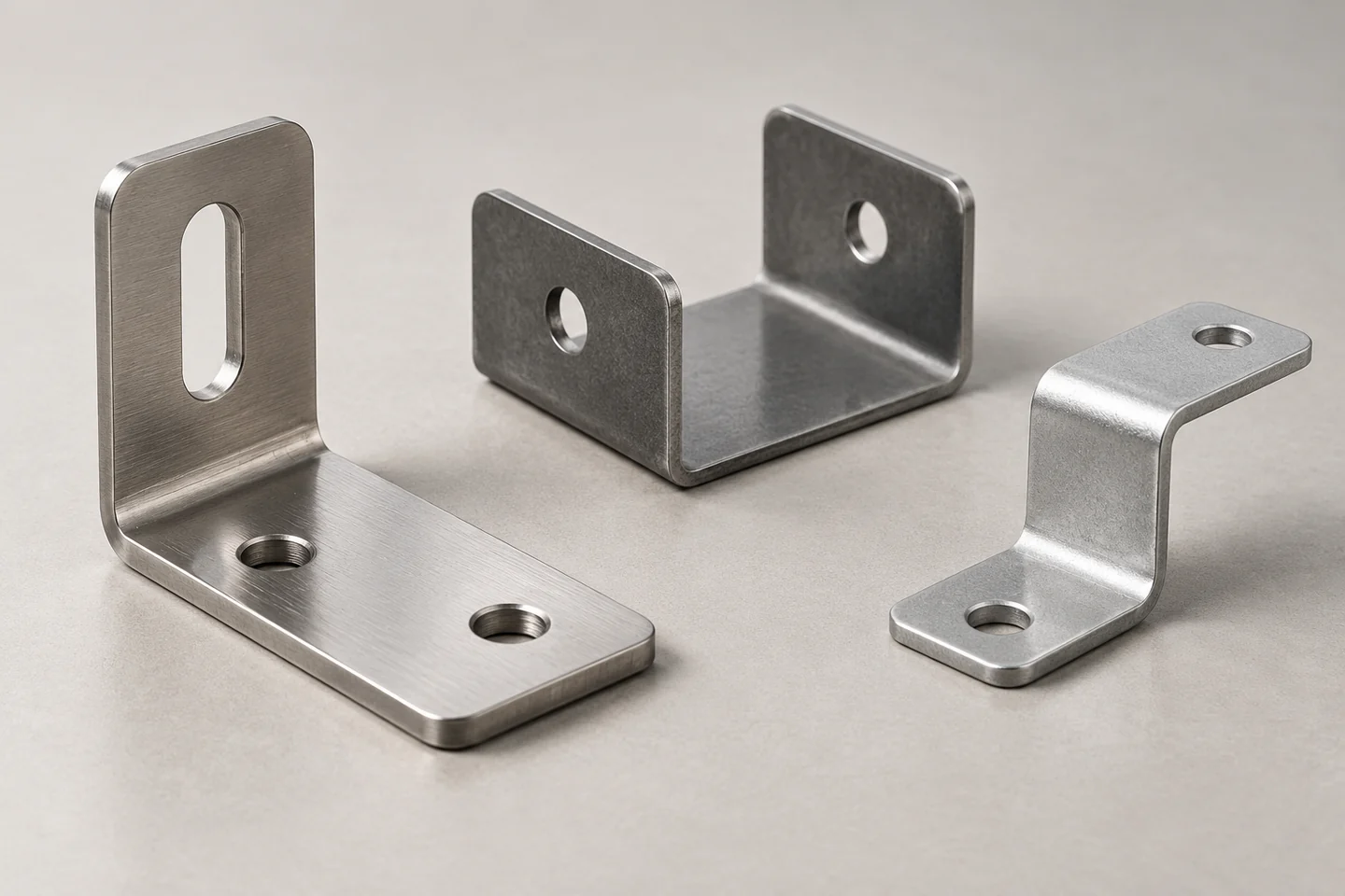
BRACKET FAMILY / L·U·Z형 구조
Structure.
지지 기능과 구조 응답을 먼저 정의합니다.
01 / FUNCTION & LOAD PATHS
형상보다 먼저, 하중이 지나가는 경로를 설계합니다
부품을 받치는 면, 위치를 정하는 기준, 힘을 전달하는 체결부를 같은 조립 조건으로 연결합니다.
첫 번째 설계 자료는 단품 형상보다 조립 상태의 자유물체도입니다. 하중의 크기와 방향, 작용 위치, 고정면의 구속, 상대 구조물의 유연성을 표시합니다. 자중뿐 아니라 가감속·케이블 반력·조립 중 외력처럼 실제로 함께 작용하는 하중을 구분하고, 동시에 발생하는 조합을 검토합니다.
기준 지점에서 힘 F의 작용선까지 수직거리가 e이면 모멘트 M = F·e가 생깁니다. 이 단순 관계는 장착 위치를 옮기는 것이 왜 중요한지 설명합니다. 그러나 실제 브래킷에서는 접촉면이 열리거나 볼트 구멍에서 미끄러지는 순간 하중 경로가 바뀔 수 있으므로, 고정 경계 전체를 완전 강체로 놓은 계산만으로 판단하지 않습니다.
도면에는 지지·위치 결정·고정을 구분합니다. 넓은 면은 하중을 받을 수 있지만 자동으로 위치 기준이 되지는 않습니다. 장공은 조립 조정에 유용하지만 허용 이동 방향과 체결 후 위치 유지 방법이 함께 정의되어야 합니다. 하중이 들어오는 곳부터 구조물로 빠져나가는 곳까지 약한 단면과 접촉 변화를 표시하면 검증 항목이 구체화됩니다.
하중 입력
방향·작용점·동시 조합과 반복 여부를 조립도에 표시합니다.
구속과 접촉
실제 받침 면적, 체결 위치와 상대 구조물의 움직임을 반영합니다.
기능 출력
허용 처짐·회전·위치 이동과 영구 변형을 판정값으로 정합니다.
형상별로 먼저 확인할 조립 조건
| 형상 | 주요 검토 | 검증에 반영할 조건 |
|---|---|---|
| L형 | 돌출 팔의 휨과 굽힘부 회전 | 하중 편심·고정면 접촉·볼트 간격 |
| U형 | 양쪽 벽의 벌어짐과 평행도 | 삽입 부품 공차·벽 사이 지지·체결 순서 |
| Z형 | 오프셋과 두 굽힘의 누적 영향 | 상하 장착면 간격·비틀림·기준 연결 |
L형
주요 검토
돌출 팔의 휨과 굽힘부 회전
검증에 반영할 조건
하중 편심·고정면 접촉·볼트 간격
U형
주요 검토
양쪽 벽의 벌어짐과 평행도
검증에 반영할 조건
삽입 부품 공차·벽 사이 지지·체결 순서
Z형
주요 검토
오프셋과 두 굽힘의 누적 영향
검증에 반영할 조건
상하 장착면 간격·비틀림·기준 연결
02 / STRENGTH, STIFFNESS & STABILITY
파손을 막는 강도와 위치를 지키는 강성을 구분합니다
응력이 허용 범위에 있어도, 변위가 크면 정밀 지지 기능은 실패할 수 있습니다.
강도 검토는 항복·파단 등 한계 상태와 관련되고, 강성 검토는 하중에 대한 변위·회전과 관련됩니다. 고강도 재료로 교체해도 탄성계수와 형상이 비슷하면 탄성 처짐이 같은 비율로 줄지 않습니다. 구조 목표를 최대 응력 하나로 모으지 말고, 장착점의 이동과 접촉면의 벌어짐까지 별도 항목으로 설정합니다.
직선·일정 직사각 단면 외팔보의 자유단에 횡방향 집중하중 F가 작용하는 작은 탄성 변형에서는 δ = FL³/(3EI), I = bt³/12로 비교할 수 있습니다. 여기서 E는 탄성계수, b는 폭, t는 휨 방향 두께, L은 유효 길이입니다. 실제 절곡부·홀·비드·체결 접촉은 이 이상화에서 빠져 있으므로 계산값을 완성 브래킷의 보증 하중으로 사용하지 않습니다.
얇은 벽이나 긴 플랜지는 국부 좌굴과 비틀림도 검토합니다. 재료 항복 이전의 불안정, 조립면의 들뜸 또는 하중 방향 전환에 따른 접촉 변화는 단순 인장강도 표에서 찾을 수 없습니다. 경계조건을 바꾸어 민감도를 살핀 뒤 실물의 하중–변위 곡선과 잔류 변형을 대조합니다.
강도
항복·파단과 국부 응력 집중을 해당 하중 조합에서 검토합니다.
강성
위치·각도·접촉 상태의 허용 변화를 지정합니다.
안정성
얇은 벽의 좌굴·비틀림과 경계조건 변화를 확인합니다.
비교 계산: 동일 재료·폭·길이의 이상적인 보에서 두께 10% 증가는 휨강성 EI를 1.1³ = 1.331배로 만듭니다. 절곡 브래킷 전체의 성능 증가율을 뜻하지 않습니다.
해석 모델을 조립 조건과 맞추는 방법
실제 조립에서 미끄러질 수 있는 면을 완전 접착으로 두거나, 변형 가능한 베이스를 강체로 두면 결과가 과도하게 단단해질 수 있습니다. 먼저 자유도와 접촉 가정을 문서화하고, 시험에서 힘을 넣는 위치와 변위를 읽는 위치를 해석에도 동일하게 적용합니다.
구조 요구를 서로 다른 판정값으로 표현하기
| 요구 | 판정값 | 확인 시 주의점 |
|---|---|---|
| 강도 여유 | 지정 하중 후 균열·영구 변형 | 소재 상태·응력 집중·하중 조합 |
| 위치 유지 | 하중 중 기준점 변위·각도 | 지그와 상대 구조물 변형 분리 |
| 안정된 접촉 | 들뜸·미끄럼·좌굴 발생 여부 | 접촉·마찰·체결 상태의 재현 |
강도 여유
판정값
지정 하중 후 균열·영구 변형
확인 시 주의점
소재 상태·응력 집중·하중 조합
위치 유지
판정값
하중 중 기준점 변위·각도
확인 시 주의점
지그와 상대 구조물 변형 분리
안정된 접촉
판정값
들뜸·미끄럼·좌굴 발생 여부
확인 시 주의점
접촉·마찰·체결 상태의 재현
Materials.
공급 상태와 전개 기준을 실제 성형 조건에 연결합니다.
03 / MATERIAL, THICKNESS & DIRECTION
소재 선택은 등급·두께·방향의 조합으로 완성됩니다
같은 재료명이라도 공급 상태가 달라지면 성형 여유와 완성 치수의 분포가 달라질 수 있습니다.
재료는 항복강도·인장강도뿐 아니라 성형성, 탄성계수, 부식 환경, 표면 요구와 공급 일관성으로 비교합니다. 강판·스테인리스강·알루미늄 합금 중 하나를 고르는 단계에서 끝내지 않고 규격·등급·조질·두께 범위와 표면 상태를 도면 및 구매 사양에 연결합니다.
두께는 구조 성능과 동시에 금형 간극, 필요한 성형력, 조립 스택 높이를 바꿉니다. 공칭 두께만으로 개발하고 양산에서 다른 허용차의 소재를 사용하면 각도와 체결면 위치가 함께 변할 수 있습니다. 실제 공급 범위의 상·하한을 고려하여 민감한 치수와 기능을 확인합니다.
압연 방향과 굽힘선의 관계가 중요한 재료는 공급사의 등급별·방향별 굽힘 자료를 우선합니다. 여러 방향으로 굽히는 부품은 가장 민감한 굽힘을 정하고 블랭크 배치와 릴리프를 함께 검토합니다. 개발에서 확정한 방향은 원자재 로트에서 전개 블랭크까지 추적 가능해야 합니다.
등급·조질
동일 계열 내에서도 공급 상태와 후속 열 이력을 구분합니다.
실제 두께
허용 범위를 구조·금형·조립 치수에 함께 반영합니다.
압연 방향
민감한 굽힘과 시험편 방향을 전개도에 표시합니다.
재료 대체는 이름이 비슷한지로 결정하지 않습니다
대체재 검토에서는 규격 간 요구값과 공급 허용차, 표면처리 적합성, 실제 성형 결과를 함께 비교합니다. 재료 성적서는 입고 상태를 설명하지만 완성 부품의 피로수명이나 굽힘부 무균열을 대신 보증하지 않습니다.
재료 계열별 검토 방향
| 재료 계열 | 선택 관점 | 개발에서 확인할 사항 |
|---|---|---|
| 저탄소강 | 성형성과 비용·공급성의 균형 | 방청 방식·표면 상태·두께 범위 |
| 스테인리스강 | 환경에 맞는 내식성과 표면 | 등급·가공경화·윤활·방향성 |
| 알루미늄 합금 | 질량과 형상·강성의 조합 | 합금·조질·굽힘성·이종금속 접촉 |
| 고강도강 | 강도 요구와 단면 설계 | 스프링백·절단면 연성·공구 부하 |
저탄소강
선택 관점
성형성과 비용·공급성의 균형
개발에서 확인할 사항
방청 방식·표면 상태·두께 범위
스테인리스강
선택 관점
환경에 맞는 내식성과 표면
개발에서 확인할 사항
등급·가공경화·윤활·방향성
알루미늄 합금
선택 관점
질량과 형상·강성의 조합
개발에서 확인할 사항
합금·조질·굽힘성·이종금속 접촉
고강도강
선택 관점
강도 요구와 단면 설계
개발에서 확인할 사항
스프링백·절단면 연성·공구 부하
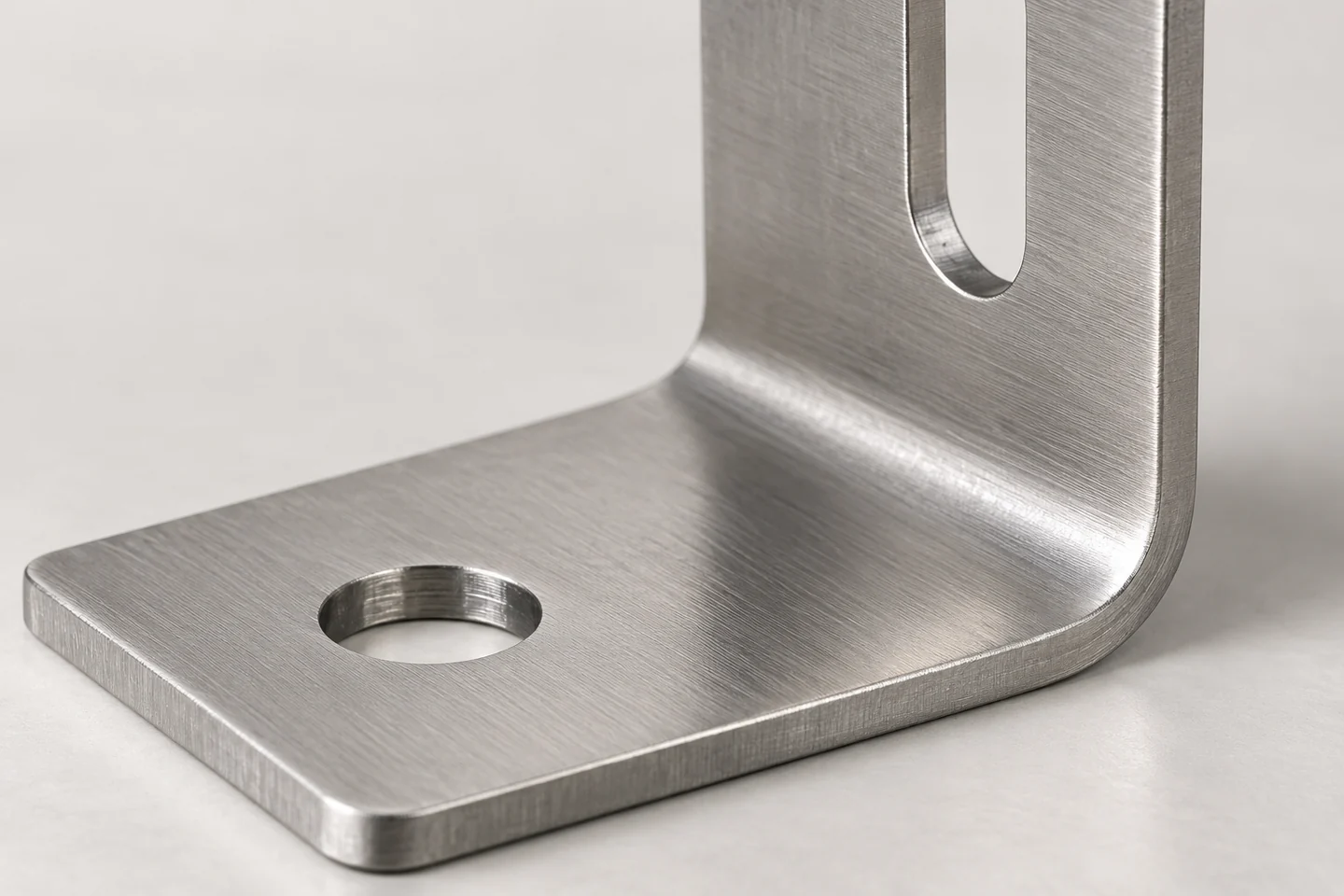
FORM & GEOMETRY / 굽힘 반경·판 두께·홀 가장자리
04 / FLAT PATTERN & FEATURE LOCATION
전개 치수와 홀 위치는 같은 기준에서 결정합니다
전개 계산의 보정값과 완성품 측정 기준이 일치해야 조립 오차를 줄일 수 있습니다.
굽힘 여유 BA = θ(R + Kt)는 중립층의 호 길이를 표현합니다. θ는 재료가 회전한 각도의 라디안값, R은 내측 반경, t는 두께, K는 내측 면에서 중립층까지 거리의 두께 대비 비입니다. 완성품의 내각과 재료의 회전각을 혼용하지 않고, 외측 가상 교점·접선점·기준면 중 어디서 치수를 읽는지 명시합니다.
K값은 모든 재료와 공구에 통용되는 고정 상수가 아닙니다. 동일 소재·두께·공구·성형 방식의 시험편에서 완성 반경·각도·플랜지 길이를 측정해 전개 테이블을 보정합니다. 전개만 맞추어도 각도 변동이 해결되는 것은 아니므로, 전개 길이 오차와 스프링백에 의한 형상 오차를 분리합니다.
홀은 중심 위치 외에도 굽힘 접선과의 가장자리 거리, 다이 지지 영역, 공구 접근과 기능 공차를 함께 봅니다. 민감한 홀을 성형 후 가공하면 최종 기준을 사용할 수 있지만 고정구와 공정이 추가됩니다. 성형 전 피어싱과 성형 후 가공을 실제 조립 요구·변형 가능성·검사 접근성으로 비교합니다.
성형 3D는 평판·굽힘 구간·제하 후 형상의 관계를 설명합니다. 재료 유동이나 실제 보정 각도를 계산하지 않습니다.
전개·홀 배치의 의사결정
| 검토 항목 | 오해하기 쉬운 점 | 도면·공정에 남길 기준 |
|---|---|---|
| 굽힘 각도 | 내각과 회전각의 혼용 | 각도 정의·측정 면·자유/구속 상태 |
| 내측 반경 | 펀치 반경과 완성 반경의 동일시 | 성형 방식과 실측 반경 |
| 홀–굽힘 관계 | 중심 거리만으로 안전성 판단 | 홀 가장자리·접선·지지 영역 |
| 릴리프·노치 | 찢김 방지만 보고 단면 손실 누락 | 끝단 형상·유효 단면·버 방향 |
굽힘 각도
오해하기 쉬운 점
내각과 회전각의 혼용
도면·공정에 남길 기준
각도 정의·측정 면·자유/구속 상태
내측 반경
오해하기 쉬운 점
펀치 반경과 완성 반경의 동일시
도면·공정에 남길 기준
성형 방식과 실측 반경
홀–굽힘 관계
오해하기 쉬운 점
중심 거리만으로 안전성 판단
도면·공정에 남길 기준
홀 가장자리·접선·지지 영역
릴리프·노치
오해하기 쉬운 점
찢김 방지만 보고 단면 손실 누락
도면·공정에 남길 기준
끝단 형상·유효 단면·버 방향
3D · 평판에서 브래킷으로
FORMING GEOMETRYID SOLUTECH / 01
90° 성형 상태
인터랙티브 3D를 준비하고 있습니다.
일정한 판 두께와 연속적인 굽힘 곡면을 유지한 90° 형상입니다. 실제 금형에는 소재·판 두께·마찰·공구 조건을 반영한 보정이 필요합니다.
드래그·방향키: 회전 / + −: 확대·축소 / Home: 초기화성형 단계와 탄성 회복
전개에서 완성 형상까지,
같은 기준으로 연결합니다.
Manufacturing.
절단과 성형을 연속된 변형 이력으로 관리합니다.
05 / CUT EDGE & PROCESS SEQUENCE
절단면의 상태가 다음 성형의 한계를 바꿉니다
낮은 버 높이와 충분한 가장자리 성형성은 서로 다른 확인 항목입니다.
블랭킹·피어싱·노칭에서 생성한 면은 이후 굽힘·확장·체결에 그대로 참여합니다. 절단면에서는 눌림, 전단면, 파단면과 버뿐 아니라 인접부의 손상·가공경화가 중요합니다. 후속 변형이 집중되는 홀과 노치의 가장자리는 외관 검사에 더해 실제 공정을 대표하는 성형 시험으로 평가합니다.
금형 간극·날 상태·소재 지지·슬러그 배출은 치수와 가장자리 상태에 동시에 영향을 줍니다. 버를 제거할 때도 홀 직경과 모서리 형상이 달라질 수 있으므로, 허용 버 방향·높이와 엣지 브레이크를 기능면별로 정합니다. 착좌면의 돌출은 체결 과정에서 눌리며 접촉 상태를 바꿀 수 있어 별도 관리가 필요합니다.
레이저 절단 시제품은 형상·조립 검토에 유용하지만 양산 전단면을 그대로 대표하지 않습니다. 가장자리의 후속 변형이 중요하다면 양산 공정으로 제작한 블랭크에서 재검증합니다. 공정 순서 또한 단순히 작업 수를 줄이는 문제가 아니라 캐리어 유지, 기준 이송, 공구 접근과 해방 후 형상의 균형입니다.
절단 간극
소재·두께에 맞는 조건과 날 마모를 함께 관리합니다.
기능 가장자리
홀·노치·굽힘 끝의 위치와 후속 변형을 연결합니다.
공정 대표성
승인 시험편의 절단 경로가 양산과 같은지 확인합니다.
소재와 변형 경로의 적용 범위를 확인합니다
고강도강의 선성형과 전단 가장자리에서는 변형 순서가 국부 연성에 영향을 줄 수 있습니다. 특정 두께·강종의 결과를 다른 브래킷에 그대로 적용하지 않고, 실제 소재와 변형 경로로 확인할 시험 항목을 정합니다.
절단부터 성형까지 이어지는 관리
| 공정 | 다음 단계의 영향 | 관리·확인 |
|---|---|---|
| 블랭킹 | 외형·압연 방향·기준 안정성 | 코일/판재 식별·위치 결정·배치 |
| 피어싱·노칭 | 가장자리 손상·홀 변형 가능성 | 간극·날 상태·버와 슬러그 |
| 굽힘·엠보싱 | 국부 신장·간섭·비대칭 변형 | 지지·윤활·순서·실물 성형성 |
| 교정·최종 분리 | 잔류 변형과 기준 이동 | 해방 후 측정·취급·다음 공정 영향 |
블랭킹
다음 단계의 영향
외형·압연 방향·기준 안정성
관리·확인
코일/판재 식별·위치 결정·배치
피어싱·노칭
다음 단계의 영향
가장자리 손상·홀 변형 가능성
관리·확인
간극·날 상태·버와 슬러그
굽힘·엠보싱
다음 단계의 영향
국부 신장·간섭·비대칭 변형
관리·확인
지지·윤활·순서·실물 성형성
교정·최종 분리
다음 단계의 영향
잔류 변형과 기준 이동
관리·확인
해방 후 측정·취급·다음 공정 영향
06 / SPRINGBACK & SHAPE CONTROL
평균 오차와 생산 중 변동을 나누어 교정합니다
각도 벌어짐, 벽 휨과 뒤틀림을 같은 현상으로 다루면 보정 방향을 놓치기 쉽습니다.
스프링백은 성형 하중이 제거될 때 나타나는 탄성 회복입니다. 최종 형상은 소재·두께·굽힘 반경뿐 아니라 변형 이력과 구속 해제 순서의 영향을 받습니다. 각도만 달라지는지, 벽 자체가 휘는지, 길이 방향으로 비틀리는지를 먼저 구분하고 그 변형을 측정할 위치를 정합니다.
일정한 방향으로 반복되는 평균 오차는 과굽힘·공구 보정의 검토 대상입니다. 반대로 같은 조건에서 형상이 넓게 흩어지면 소재 편차·위치 결정·윤활·금형 상태를 먼저 조사합니다. 불안정한 분포를 한 번의 공구 수정으로 맞추려 하면 다른 로트에서 반대 오차가 발생할 수 있습니다.
성형 해석은 재료의 다축 거동과 변형 경로, 접촉·마찰 가정이 실제 공정을 설명할 때 유용합니다. 단순 인장 데이터만으로 복잡한 성형 후 회복을 충분히 표현할 수 있는지 확인합니다. 예측 결과는 금형 안의 형상보다 취출·최종 분리·후처리 후 형상과 비교해야 개발 판단에 직접 연결됩니다.
평균 형상
같은 방향으로 반복되는 오차의 크기와 위치를 찾습니다.
분포 폭
소재 로트·설정·시간에 따른 변동을 분리합니다.
해방 상태
지지·클램프·측정 위치를 동일하게 유지합니다.
리스트라이크를 추가할 때 확인할 것
재성형은 형상을 조정하지만 국부 가공경화·표면 압흔·공구 하중도 바꿀 수 있습니다. 교정 전후의 기능 치수와 표면을 비교하고, 다음 절단이나 표면처리 후에도 조정 효과가 유지되는지 확인합니다. 검사 지그로 눌러 맞춘 결과는 자유 상태 결과와 구별하여 기록합니다. 시편 위치와 채취 조건도 측정 결과에 영향을 줄 수 있으므로 함께 관리합니다.
형상 변화와 원인 조사 방향
| 변형 모드 | 측정할 모습 | 조사 방향 |
|---|---|---|
| 각도 변화 | 두 평면 사이 각도 차이 | 소재·두께·성형 깊이·보정 조건 |
| 벽 휨 | 평면이어야 할 벽의 곡률 | 굽힘–펴짐 이력·응력 분포 |
| 뒤틀림 | 길이별 단면 회전 | 비대칭 형상·구속·윤활·위치 |
| 국부 들뜸 | 기준면의 부분 접촉 | 국부 성형·분리 순서·버·표면 |
각도 변화
측정할 모습
두 평면 사이 각도 차이
조사 방향
소재·두께·성형 깊이·보정 조건
벽 휨
측정할 모습
평면이어야 할 벽의 곡률
조사 방향
굽힘–펴짐 이력·응력 분포
뒤틀림
측정할 모습
길이별 단면 회전
조사 방향
비대칭 형상·구속·윤활·위치
국부 들뜸
측정할 모습
기준면의 부분 접촉
조사 방향
국부 성형·분리 순서·버·표면
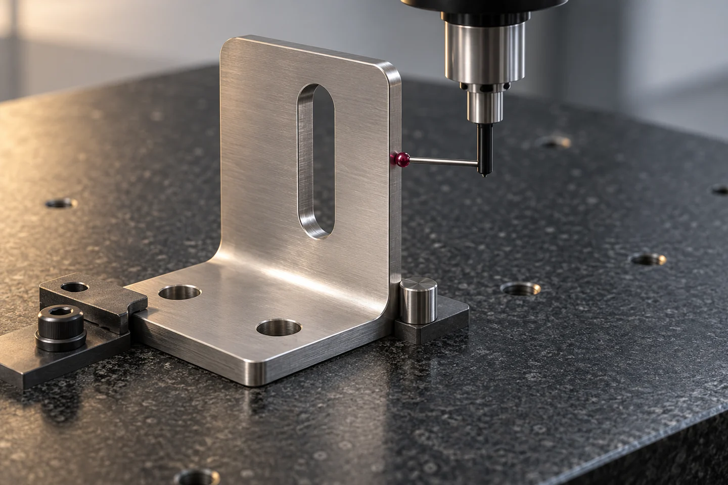
VALIDATION / 기준·측정·조립 상태의 연결
Assembly.
보강 형상과 체결 조건을 하나의 구조로 연결합니다.
07 / REINFORCEMENT & SECTION DESIGN
보강은 힘의 흐름에 맞춰 단면을 배치하는 일입니다
비드·리턴 플랜지·거싯은 높이와 위치, 끝단의 연결 방식이 함께 중요합니다.
평판의 일부를 면 밖으로 이동시키는 보강은 단면의 재료 배치를 바꾸어 휨과 비틀림 응답을 조정합니다. 그러나 하중과 무관한 방향의 비드, 장착면을 가로지르는 보강 또는 급하게 끝나는 거싯은 다른 문제를 만들 수 있습니다. 먼저 취약한 변형 모드와 힘의 유입·유출 위치를 파악한 뒤 보강 방향을 정합니다.
리턴 플랜지는 단면 높이를 확보하지만 취출·조립 공구 접근과 인접 부품 간섭을 제한할 수 있습니다. 비드와 엠보싱은 평면부를 보강하는 동시에 재료 유동과 국부 박육을 요구합니다. 거싯의 시작과 끝, 홀 근처의 전이부는 하중 집중과 성형 균열을 함께 확인해야 합니다.
후보 형상은 질량만 같게 비교하는 것으로 충분하지 않습니다. 같은 설치 공간·기준면·허용 변위·제조 경로에서 두께 증가, 플랜지 추가와 비드 배치를 비교합니다. 설계 해석과 실물 비교에서 가장자리 상태와 실제 체결을 맞추면, 형상 변경의 효과와 공정 차이의 효과를 구분하기 쉬워집니다.
리턴 플랜지
단면 높이·비틀림과 조립 공구 접근을 함께 검토합니다.
비드·엠보싱
하중 방향·끝단 전이와 재료 유동 여유를 확인합니다.
거싯·리브
힘의 연결 위치와 성형부 균열·박육을 살펴봅니다.
보강·체결 3D의 색상과 이동은 부품 관계를 설명하기 위한 표시입니다. 응력 분포·안전율·강성 향상률을 나타내지 않습니다.
보강의 끝단을 검토 목록에 넣습니다
보강부가 갑자기 끝나는 위치는 평판으로 힘을 되돌리는 전이 영역입니다. 끝단 반경과 길이, 인접 홀·굽힘의 간격을 검토하고, 하중 시험에서 이 위치의 변형과 균열을 관찰합니다. 모양이 단단해 보인다는 이유로 반복하중 성능을 확정하지 않습니다.
보강 대안의 이점과 검증 과제
| 대안 | 기대하는 역할 | 추가 확인 |
|---|---|---|
| 두께 증가 | 단면 성능과 국부 지지 개선 | 질량·성형력·굽힘·조립 스택 |
| 리턴 플랜지 | 단면 높이와 가장자리 지지 | 간섭·공구 접근·취출 |
| 비드·엠보싱 | 평판부 변형 모드 조정 | 박육·균열·끝단 전이·외관 |
| 거싯·리브 | 굽힘부 인근 하중 전달 보완 | 성형성·접합 영향·피로 집중 |
두께 증가
기대하는 역할
단면 성능과 국부 지지 개선
추가 확인
질량·성형력·굽힘·조립 스택
리턴 플랜지
기대하는 역할
단면 높이와 가장자리 지지
추가 확인
간섭·공구 접근·취출
비드·엠보싱
기대하는 역할
평판부 변형 모드 조정
추가 확인
박육·균열·끝단 전이·외관
거싯·리브
기대하는 역할
굽힘부 인근 하중 전달 보완
추가 확인
성형성·접합 영향·피로 집중
3D · 보강과 체결의 하중경로
JOINT & LOAD PATHID SOLUTECH / 02
체결 조립
인터랙티브 3D를 준비하고 있습니다.
장공·와셔·볼트·상대 부재의 정렬과 접근성을 함께 확인합니다. 화살표는 정성적 하중경로이며, 체결 토크·미끄럼 저항·강도값을 표시하지 않습니다.
드래그·방향키: 회전 / + −: 확대·축소 / Home: 초기화브래킷·거싯·볼트 체결 구조
08 / FASTENING, PRELOAD & LOCATION
체결 토크보다 먼저, 접합면이 어떻게 지지되는지 봅니다
볼트·와셔·브래킷·상대 구조물의 변형이 함께 체결 상태를 결정합니다.
체결은 볼트가 있는지보다 접합면이 어떻게 눌리고 외력을 전달하는지가 핵심입니다. 얇은 판에서는 볼트 머리나 와셔 아래의 국부 눌림, 홀 가장자리의 지압과 파손, 들뜸에 따른 지렛대 효과를 함께 살펴야 합니다. 볼트 강도만 높여도 판재의 지지 능력이 자동으로 증가하지는 않습니다.
체결 토크는 축력의 직접 측정값이 아닙니다. 나사와 좌면의 마찰, 윤활·코팅·공구 조건에 따라 같은 토크의 결과가 달라집니다. 체결 사양을 개발할 때에는 실제 표면 조합과 조립 순서를 사용하고, 축력 확보와 판재 손상을 함께 검증합니다. 외력에 따른 볼트 하중 증분은 접합부 강성 및 접촉 상태에 의존합니다.
장공과 큰 여유 홀은 조립 오차를 흡수하지만 위치 결정이나 반복 미끄럼을 별도로 해결해야 합니다. 위치가 중요하다면 기준 홀·핀·형상 맞춤의 역할을 지정하고, 조정 후 고정되는 방향을 명확히 합니다. 체결 해체 후 재사용 여부와 현장 조립 조건도 승인 사양에 포함합니다.
체결 검증 = 축력 + 접촉 상태 + 판재 지지
토크값 하나의 적합 여부보다, 실제 조립에서 필요한 위치와 접합 상태가 유지되는지를 확인하는 검토식입니다. 수치 계산 공식이 아닙니다.
와셔 확대의 효과와 한계
와셔는 좌면 하중을 더 넓게 전달할 수 있지만 주변 형상·평탄도·와셔 강성에 따라 실제 접촉이 달라집니다. 와셔 외경만 늘리는 변경은 홀 주변 굽힘이나 간섭을 만들 수 있으므로 체결 후 접촉 자국, 국부 눌림과 기능 위치를 함께 확인합니다.
체결 실패 경로별 검토
| 현상 | 구조적 원인 후보 | 확인할 결과 |
|---|---|---|
| 장착 위치 이동 | 여유 홀·마찰 부족·국부 미끄럼 | 조립 전후 위치·반복하중 후 이동 |
| 좌면 눌림 | 지지 면적·판 두께·높은 축력 | 압흔·잔류 변형·축력 유지 |
| 홀 변형·가장자리 파손 | 지압·순단면·끝단 거리 | 홀 형상·균열·하중 방향 |
| 들뜸·볼트 피로 | 편심·접합부 유연성·프라잉 | 접촉 개방·볼트 응답·반복시험 |
장착 위치 이동
구조적 원인 후보
여유 홀·마찰 부족·국부 미끄럼
확인할 결과
조립 전후 위치·반복하중 후 이동
좌면 눌림
구조적 원인 후보
지지 면적·판 두께·높은 축력
확인할 결과
압흔·잔류 변형·축력 유지
홀 변형·가장자리 파손
구조적 원인 후보
지압·순단면·끝단 거리
확인할 결과
홀 형상·균열·하중 방향
들뜸·볼트 피로
구조적 원인 후보
편심·접합부 유연성·프라잉
확인할 결과
접촉 개방·볼트 응답·반복시험
브래킷의 성능은,
조립된 구조에서 완성됩니다.
Reliability.
사용 이력과 환경을 시험 조건으로 번역합니다.
09 / VIBRATION & FATIGUE
정적 합격 이후에 반복하중의 경로를 검증합니다
정하중을 견딘 사실만으로 진동 중 위치 유지와 장기 내구를 판단하지 않습니다.
브래킷은 본체의 가진, 장착물 관성, 회전기기 진동과 케이블 반력 등 서로 다른 반복 입력을 받을 수 있습니다. 입력 위치와 방향, 주파수 성분, 크기와 사용 시간을 정의해야 시험을 제품 사용과 연결할 수 있습니다. 시험 지그의 공진이나 과도한 고정 강성이 결과를 바꾸지 않는지도 검토합니다.
국부 응력 집중은 굽힘 끝, 절단면, 홀과 보강 끝단에서 발생할 수 있습니다. 성형 잔류응력·표면 상태·조립 예압은 반복 응답에 함께 작용하므로, 평활한 재료 시험편의 수명 자료를 그대로 완성품 수명으로 환산하지 않습니다. 필요한 경우 하중 이력과 국부 변형을 계측하여 계산 가정을 검증합니다.
반복시험의 종료 기준은 균열만으로 한정하지 않습니다. 위치 이동, 체결 풀림, 강성 변화, 소음과 기능 간섭이 먼저 문제가 될 수 있습니다. 시험 전후에 동일 기준의 치수·접촉 상태·하중–변위 응답을 비교하고, 중간 점검 시점과 허용 변화량을 사전에 정합니다.
진동 시험법은 입력의 형식을 정하는 자료입니다. 실제 제품의 시험 수준·축·시간·장착 조건과 합격 기준은 사용 환경에 맞추어 별도로 정합니다.
공진을 발견했을 때의 설계 선택
공진 응답은 질량·강성·감쇠와 경계조건의 조합입니다. 두께를 늘리는 것 외에 장착물 위치, 지지 간격, 보강 방향과 체결 접촉을 바꾸는 대안을 비교합니다. 한 조건의 공진 주파수만 이동시킨 뒤 전체 사용 범위의 입력과 간섭 여부를 다시 확인합니다.
반복·진동 검증에 필요한 정의
| 입력·판정 | 정의할 내용 | 해석·시험 연결 |
|---|---|---|
| 하중 이력 | 방향·진폭·평균 하중·횟수 | 실사용 조합과 반복시험 대응 |
| 가진 조건 | 주파수·축·레벨·시간 | 지그·장착물·경계조건 재현 |
| 국부 취약부 | 굽힘·홀·절단면·보강 끝 | 변형 계측·균열 관찰 위치 |
| 기능 종료 | 이동·풀림·처짐·소음 | 전후 비교와 중간 점검 기준 |
하중 이력
정의할 내용
방향·진폭·평균 하중·횟수
해석·시험 연결
실사용 조합과 반복시험 대응
가진 조건
정의할 내용
주파수·축·레벨·시간
해석·시험 연결
지그·장착물·경계조건 재현
국부 취약부
정의할 내용
굽힘·홀·절단면·보강 끝
해석·시험 연결
변형 계측·균열 관찰 위치
기능 종료
정의할 내용
이동·풀림·처짐·소음
해석·시험 연결
전후 비교와 중간 점검 기준
10 / SURFACE & ENVIRONMENT
표면처리는 환경과 조립 기능을 함께 만족해야 합니다
방청 사양은 처리명·색상에 더해 기능면, 절단면과 체결 상태까지 연결합니다.
표면처리를 선택할 때에는 습기·염분·세정제·온도와 이종금속 접촉을 확인합니다. 겹침부와 수분 체류 구간, 손상되기 쉬운 모서리의 환경은 넓은 평면과 다를 수 있습니다. 접지·전기적 연결이 필요한 경우에는 절연성 코팅과 접촉 저항 요구도 별도로 조율합니다.
코팅은 홀·나사·끼워맞춤과 체결 마찰에 영향을 줄 수 있습니다. 치수를 처리 전후 중 어느 상태에서 판정할지 정하고, 마스킹 영역·배수·걸이 자국·허용 외관을 표시합니다. 선처리 판재를 절단한 가장자리와 성형 후 처리한 부품은 보호층의 연속성과 공정 접근 조건이 다릅니다.
염수분무 결과는 정의된 조건에서 코팅과 시편을 비교하는 정보입니다. 시험 시간으로 실제 설치 수명을 일률 환산하지 않습니다. 시험편 준비, 절단면 보호 여부, 부식 평가 위치와 허용 상태를 지정하고, 필요하면 실제 환경을 반영한 반복 습윤·건조나 조립체 시험을 함께 설계합니다.
사용 환경
수분·염분·온도·세정제와 이종금속 조합을 확인합니다.
기능면
체결·위치·끼워맞춤과 전기 연결 요구를 구분합니다.
납품 상태
처리 후 치수·청정도·포장과 보관 조건을 연결합니다.
고강도 부품의 수소취성 검토
산 세척과 전해 도금 등 수소 유입 가능 공정이 있고 소재가 민감하다면, 재료·경도·공정에 맞는 예방과 검증을 검토합니다. 모든 강판에 같은 위험 수준이나 후열처리를 적용하지 말고, 적용 규격과 공급망의 승인 공정으로 조건을 정합니다.
표면 사양을 기능에 연결하기
| 영역 | 영향 | 사양·검증 항목 |
|---|---|---|
| 절단·굽힘부 | 노출 모재·코팅 손상·부식 시작 | 처리 순서·경계 상태·관찰 위치 |
| 체결 좌면 | 마찰·축력·국부 압흔 | 실제 조합의 체결 검증 |
| 홀·끼워맞춤 | 막 두께와 치수 변화 | 최종 상태 치수·마스킹·게이지 |
| 겹침·포장 | 잔류액·이종금속·운송 손상 | 배수·건조·분리·보관 조건 |
절단·굽힘부
영향
노출 모재·코팅 손상·부식 시작
사양·검증 항목
처리 순서·경계 상태·관찰 위치
체결 좌면
영향
마찰·축력·국부 압흔
사양·검증 항목
실제 조합의 체결 검증
홀·끼워맞춤
영향
막 두께와 치수 변화
사양·검증 항목
최종 상태 치수·마스킹·게이지
겹침·포장
영향
잔류액·이종금속·운송 손상
사양·검증 항목
배수·건조·분리·보관 조건
Validation.
측정과 양산 판정이 같은 기능 기준을 사용하도록 합니다.
11 / DATUMS & MEASUREMENT
측정은 값을 읽기 전에 기준을 재현하는 과정입니다
얇은 부품에서는 고정 방법이 측정 결과의 일부가 될 수 있습니다.
검사 기준은 조립에서 필요한 위치 관계를 반영해야 합니다. 주 기준면·방향을 잡는 특징·최종 위치를 제한하는 특징을 명확히 하고, 홀 위치와 장착면 높이를 그 체계에서 읽습니다. 3차원 스캔이나 CMM 결과도 정렬 방식이 달라지면 같은 의미의 치수 비교가 되지 않을 수 있습니다.
자유 상태와 구속 상태는 서로 다른 질문에 답합니다. 자유 상태는 성형품 자체의 형상을, 지정 구속 상태는 조립 조건에서의 적합성을 보여 줍니다. 검사 지그의 지지점·클램프 순서·힘과 프로브 가압력을 정의하지 않으면 검사자가 부품을 누르는 정도에 따라 판정이 바뀔 수 있습니다.
측정계는 반복성과 재현성뿐 아니라 분해능·바이어스·안정성·불확도를 검토합니다. 도면 한계 가까이 있는 값에 대해서는 판정 규칙을 합의하고, 측정 능력이 충분하지 않다면 공정능력 수치를 계산하기 전에 측정 방법부터 개선합니다. 검사 기준과 실제 조립에서 요구하는 기준이 일치하는지 승인 시편으로 확인합니다.
기준 체계
장착면·기준 홀·방향 결정의 역할을 분리합니다.
측정 상태
자유/구속·지지·클램프·최종 표면 상태를 지정합니다.
측정 신뢰성
방법·작업자·시간에 따른 차이를 확인합니다.
도면에 적용하는 기하공차 체계와 판본을 명시합니다. ISO GPS와 ASME의 정의를 기호 모양만 보고 혼용하지 않습니다.
합격 판정에 가까운 측정값
측정값에는 불확도가 있으므로 한계값 부근에서는 측정 방법과 판정 규칙이 중요해집니다. 필요한 기능에 비해 지나치게 좁은 공차를 지정하거나 측정 조건을 비워 두기보다, 기능·공정·측정의 세 조건을 함께 검토하여 재현 가능한 승인 기준을 만듭니다.
검사 계획에 남겨야 할 정의
| 항목 | 필수 정의 | 판정 연결 |
|---|---|---|
| 기준면·홀 | 기준 순서·접촉·정렬 방식 | 조립 위치와 방향 |
| 각도·평탄도 | 측정 면·길이·지지 상태 | 장착면 밀착과 간섭 |
| 치수·표면 | 처리 전후·온도·버 기준 | 최종 납품 상태 적합성 |
| 측정계 | 장비·방법·반복성·불확도 | 한계 부근 판정과 데이터 신뢰성 |
기준면·홀
필수 정의
기준 순서·접촉·정렬 방식
판정 연결
조립 위치와 방향
각도·평탄도
필수 정의
측정 면·길이·지지 상태
판정 연결
장착면 밀착과 간섭
치수·표면
필수 정의
처리 전후·온도·버 기준
판정 연결
최종 납품 상태 적합성
측정계
필수 정의
장비·방법·반복성·불확도
판정 연결
한계 부근 판정과 데이터 신뢰성
12 / PRODUCTION READINESS & CHANGE CONTROL
양산 승인은 한 개의 양품보다 재현 가능한 조건입니다
도면·소재·금형·표면·검사와 변경 이력을 한 개정 체계로 연결합니다.
개발 완료 시점에는 형상 데이터뿐 아니라 기능 요구, 소재 공급 상태, 중요 공정 변수와 검사 방법이 함께 확정되어야 합니다. 초기 양품이 어떤 소재 로트·금형·설정·표면처리 조건에서 만들어졌는지 남기고, 양산에서 변동하기 쉬운 입력과 그에 따른 기능 영향을 구분합니다.
공정능력 지표를 사용할 때에는 공정의 안정성과 측정계 적합성을 먼저 확인합니다. 여러 설정이나 서로 다른 로트가 섞인 데이터, 시간에 따른 추세가 있는 데이터로 얻은 단일 지표는 원인을 숨길 수 있습니다. 관리할 특성·표본 추출·분포 가정·반응 계획을 정하고 고객 요구에 맞추어 판단합니다.
소재·두께·공급사·금형 수리·윤활·코팅·공정 순서를 바꿀 때에는 영향을 받는 치수와 기능을 먼저 정합니다. 치수 재검사로 충분한지, 성형성·체결·반복하중·환경시험을 다시 해야 하는지 변경 영향에 따라 결정합니다. 양산성은 부품 단가뿐 아니라 조립 시간, 불량·재작업과 검사 부담을 함께 비교해야 합니다.
설계 입력
동일 개정 2D·3D와 조립 조건·기능 기준을 준비합니다.
제조 승인
대표 공정·소재·표면의 승인 시편과 기록을 연결합니다.
양산 관리
로트 추적·검사·이상 반응·변경 재승인을 정합니다.
제작 검토를 위한 자료 패키지
아이디솔루텍에 검토를 의뢰할 때에는 2D·3D 도면, 용도와 하중 조건, 장착 상대품, 재료·표면 요구, 중요 치수, 예상 수량과 일정, 필요한 시험을 함께 전달해 주세요. 미정 항목은 확정값처럼 기입하기보다 개발에서 확인할 조건으로 표시하면 검토 범위를 명확히 정할 수 있습니다.
개발 의뢰와 양산 승인 자료
| 자료 | 포함할 내용 | 연결되는 판단 |
|---|---|---|
| 형상·기준 | 동일 개정 도면·조립도·기준과 공차 | 전개·금형·측정 방법 |
| 사용 조건 | 하중·변위·진동·환경·체결 | 구조·내구·환경 검증 |
| 제조·표면 | 재료 상태·공정·버·처리·포장 | 공정 대표성·납품 품질 |
| 양산·변경 | 수량·주기·로트·승인·반응 계획 | 공정능력·추적성·재검증 |
형상·기준
포함할 내용
동일 개정 도면·조립도·기준과 공차
연결되는 판단
전개·금형·측정 방법
사용 조건
포함할 내용
하중·변위·진동·환경·체결
연결되는 판단
구조·내구·환경 검증
제조·표면
포함할 내용
재료 상태·공정·버·처리·포장
연결되는 판단
공정 대표성·납품 품질
양산·변경
포함할 내용
수량·주기·로트·승인·반응 계획
연결되는 판단
공정능력·추적성·재검증
재현 가능한 품질은
설계·공정·검증의 일관성에서 나옵니다.
개발 상담 · Contact
연락처 · Get in Touch
기술 협의 · Engineering Consultation
도면과 사양을 기준으로 소재·가공·표면처리,
주요 품질 항목과 공급 조건을 함께 검토합니다.
We review drawings and specifications to define materials, manufacturing methods, surface finishes, key quality requirements, and supply conditions.
주요 품질 항목과 공급 조건을 함께 검토합니다.
We review drawings and specifications to define materials, manufacturing methods, surface finishes, key quality requirements, and supply conditions.
개발 의뢰하기 · Development Inquiry
PRECISION BRACKET
ENGINEERING
Transfer loads.
Preserve position.
Connect material and forming with assembly function.
From design inputs to production validation.
Loads · Materials · Forming
Reinforcement · Joints · Validation
ENGLISH EDITION
Precision Metal Brackets
From Design Requirements to Production Validation
Precision support begins by designing load, geometry and assembly together.
A precision bracket is defined by more than its final bend angle. It must maintain the position of the supported component, transfer loads and repeat those functions after forming, fastening and finishing. ID SOLUTECH approaches a stamped sheet-metal bracket as a connected system, linking design inputs and manufacturing conditions to final validation.
This article covers L-, U- and Z-shaped brackets and reinforced sheet-metal supports used in equipment, enclosures and frames. Calculations and material data support development decisions; allowable loads, tolerances and life require validation against the individual drawing and service conditions.
BRACKET FAMILY / L, U and Z forms
Structure.
Define the supporting function and structural response first.
01 / FUNCTION & LOAD PATHS
Design the Load Path Before Choosing the Outline
Connect supporting surfaces, locating datums and fasteners within the same assembly definition.
Begin with a free-body diagram of the assembled system. Identify load magnitude, direction and application point, mounting restraint and the flexibility of the mating structure. Distinguish gravity from acceleration, cable reaction and assembly loads, then examine combinations that can actually occur together.
A force F whose line of action is a perpendicular distance e from the reference point produces a moment M = F·e. This simple relation explains the value of moving a mounting point. In an actual bracket, however, joint separation or slip at a clearance hole can change the load path. A model that treats the entire mounting boundary as perfectly rigid is therefore only one possible representation.
Specify support, location and clamping as separate functions. A broad bearing face is not automatically a locating datum. A slot can accommodate assembly adjustment, but its permitted motion and the means of maintaining position after tightening must be defined. Following the load into and out of the bracket identifies narrow sections and changing contacts that deserve verification.
Applied loads
Mark direction, application point, simultaneous combinations and repetition on the assembly.
Restraint and contact
Represent the actual support area, fasteners and movement of the mating structure.
Functional response
Define limits for deflection, rotation, displacement and permanent set.
Assembly Conditions to Examine by Bracket Form
| Form | Primary review | Conditions for validation |
|---|---|---|
| L-bracket | Cantilever bending and bend-root rotation | Load eccentricity, mounting contact and bolt spacing |
| U-bracket | Wall spreading and parallelism | Insert tolerances, support between walls and tightening sequence |
| Z-bracket | Offset and accumulated bend effects | Spacing of mounting planes, twist and datum relationships |
L-bracket
Primary review
Cantilever bending and bend-root rotation
Conditions for validation
Load eccentricity, mounting contact and bolt spacing
U-bracket
Primary review
Wall spreading and parallelism
Conditions for validation
Insert tolerances, support between walls and tightening sequence
Z-bracket
Primary review
Offset and accumulated bend effects
Conditions for validation
Spacing of mounting planes, twist and datum relationships
02 / STRENGTH, STIFFNESS & STABILITY
Separate Resistance to Failure from Resistance to Movement
Acceptable stress does not guarantee acceptable positioning when deflection is excessive.
Strength concerns limit states such as yielding or fracture, while stiffness concerns displacement and rotation under load. A higher-strength material does not reduce elastic deflection in the same proportion when elastic modulus and geometry remain similar. Set separate requirements for mounting-point movement and opening of the contact interface instead of using maximum stress as the sole objective.
For a straight cantilever of uniform rectangular cross-section undergoing small elastic deformation under a transverse point load F at its free end, δ = FL³/(3EI) and I = bt³/12 provide a useful comparison. E is elastic modulus, b is width, t is the dimension through the bending depth and L is effective length. Bends, holes, beads and fastening contacts are absent from this idealization; its result is not a rated load for the finished bracket.
Thin walls and long flanges also require review for local buckling and torsion. Instability before yielding, mounting-face lift and changing contact during load reversal are not captured by a tensile-strength value. Examine sensitivity to boundary conditions, then compare the model with measured load–displacement behavior and residual set.
Strength
Review yielding, fracture and local stress concentration for each load combination.
Stiffness
Specify permitted changes in position, angle and contact condition.
Stability
Check thin-wall buckling, torsion and changing boundary conditions.
Comparison only: increasing thickness by 10% raises EI by 1.1³ = 1.331 for an ideal beam of unchanged material, width and length. This is not a performance multiplier for an entire formed bracket.
Match the model to the assembly
Bonding an interface that can slip, or making a flexible base rigid, can overstate stiffness. Document degrees of freedom and contact assumptions, and use the same load-application and displacement-measurement locations in analysis and testing.
Express Structural Requirements as Distinct Acceptance Measures
| Requirement | Acceptance measure | Review consideration |
|---|---|---|
| Strength margin | Cracking and permanent set after specified load | Material condition, stress concentration and load combinations |
| Position retention | Datum-point displacement and angle under load | Separate fixture and mating-structure compliance |
| Stable contact | Separation, slip or buckling | Reproduce contact, friction and fastening conditions |
Strength margin
Acceptance measure
Cracking and permanent set after specified load
Review consideration
Material condition, stress concentration and load combinations
Position retention
Acceptance measure
Datum-point displacement and angle under load
Review consideration
Separate fixture and mating-structure compliance
Stable contact
Acceptance measure
Separation, slip or buckling
Review consideration
Reproduce contact, friction and fastening conditions
Materials.
Connect material supply condition and flat-pattern definition to forming.
03 / MATERIAL, THICKNESS & DIRECTION
Select the Grade, Thickness and Orientation Together
Different supply conditions within a material family can change forming margin and dimensional variation.
Compare materials by formability, elastic modulus, corrosion environment, surface requirements and supply consistency as well as yield and tensile strength. Choosing steel, stainless steel or aluminum is only the beginning; connect the specification, grade, temper, thickness range and surface condition to both the drawing and purchasing requirements.
Thickness affects die clearance, forming force and the assembled stack as well as structural response. Development at nominal thickness followed by production with a different supply tolerance can shift both bend angle and mounting-face position. Check sensitive dimensions and functions over the actual incoming thickness range.
Where orientation affects bendability, use supplier data specific to grade and direction relative to the bend line. Parts with bends in several directions require identification of the most demanding bend, followed by review of blank orientation and relief geometry. Preserve the approved orientation from material lot to flat blank.
Grade and temper
Distinguish supply condition and subsequent thermal history within each material family.
Actual thickness
Include the supply range in structural, tooling and assembly reviews.
Rolling direction
Mark sensitive bends and specimen orientation on the flat pattern.
Do not approve a substitution by a similar name
Compare specification requirements, supply tolerances, finishing compatibility and actual forming results. A material certificate describes the supplied material; it does not establish fatigue life or freedom from cracks in the finished bend.
Review Priorities by Material Family
| Material family | Selection perspective | Development checks |
|---|---|---|
| Low-carbon steel | Balance of formability, cost and availability | Corrosion protection, surface condition and thickness range |
| Stainless steel | Corrosion and surface requirements for the environment | Grade, work hardening, lubrication and orientation |
| Aluminum alloy | Combined mass, geometry and stiffness objectives | Alloy, temper, bendability and dissimilar-metal contact |
| High-strength steel | Strength requirements and section design | Springback, cut-edge ductility and tool loading |
Low-carbon steel
Selection perspective
Balance of formability, cost and availability
Development checks
Corrosion protection, surface condition and thickness range
Stainless steel
Selection perspective
Corrosion and surface requirements for the environment
Development checks
Grade, work hardening, lubrication and orientation
Aluminum alloy
Selection perspective
Combined mass, geometry and stiffness objectives
Development checks
Alloy, temper, bendability and dissimilar-metal contact
High-strength steel
Selection perspective
Strength requirements and section design
Development checks
Springback, cut-edge ductility and tool loading
FORM & GEOMETRY / Bend radius, sheet thickness and hole edges
04 / FLAT PATTERN & FEATURE LOCATION
Define Flat-Pattern Dimensions and Hole Locations from Shared Datums
Flat-pattern compensation must correspond to the way the finished part is measured.
Bend allowance BA = θ(R + Kt) expresses arc length at the neutral layer. θ is the material rotation in radians, R the inside radius, t the thickness and K the neutral-layer distance from the inside face divided by thickness. Distinguish material rotation from the final included angle, and specify whether dimensions reference virtual sharp intersections, tangent points or datum surfaces.
K is not a universal constant for every material and tool. Calibrate a bend table using measured radius, angle and flange lengths from trials with the intended material, thickness, tooling and forming method. Correcting a flat pattern does not by itself remove angle variation; separate developed-length error from the shape change caused by springback.
For a hole, review its edge distance from the bend tangent, die support, tool access and functional tolerance as well as its center location. Machining after forming can use finished datums, but adds fixturing and operations. Compare pre-piercing and post-form machining against assembly requirements, deformation risk and inspection access.
The forming model explains the relationship between the flat blank, bend region and released shape. It does not calculate material flow or the required compensation angle.
Decisions for Flat Patterns and Feature Locations
| Item | Potential misinterpretation | Drawing or process definition |
|---|---|---|
| Bend angle | Confusing included angle with rotation | Angle definition, measured faces and free/restrained condition |
| Inside radius | Assuming punch radius equals final radius | Forming method and measured radius |
| Hole-to-bend relationship | Judging suitability only by center distance | Hole edge, tangent and support area |
| Relief and notch | Preventing tearing while ignoring section loss | End shape, effective section and burr direction |
Bend angle
Potential misinterpretation
Confusing included angle with rotation
Drawing or process definition
Angle definition, measured faces and free/restrained condition
Inside radius
Potential misinterpretation
Assuming punch radius equals final radius
Drawing or process definition
Forming method and measured radius
Hole-to-bend relationship
Potential misinterpretation
Judging suitability only by center distance
Drawing or process definition
Hole edge, tangent and support area
Relief and notch
Potential misinterpretation
Preventing tearing while ignoring section loss
Drawing or process definition
End shape, effective section and burr direction
3D · From blank to bracket
FORMING GEOMETRYID SOLUTECH / 01
Formed · 90°
Preparing the interactive 3D model.
The 90° geometry retains continuous bend surfaces and uniform gauge. Real tooling compensation depends on material, thickness, friction and process conditions.
Drag / arrow keys: rotate · + −: zoom · Home: resetForming stages and elastic recovery
Connect the flat pattern
to the finished geometry.
Manufacturing.
Manage cutting and forming as a continuous deformation history.
05 / CUT EDGE & PROCESS SEQUENCE
The Cut Edge Changes the Margin of the Next Forming Operation
A low burr and adequate edge formability are separate quality characteristics.
Surfaces created by blanking, piercing and notching participate in later bending, expansion and fastening. In addition to rollover, burnish, fracture and burr, consider damage and work hardening adjacent to the cut. Evaluate edges near highly strained holes and notches through forming trials representative of the intended process, as well as visual inspection.
Die clearance, cutting-edge condition, material support and slug evacuation affect both dimensions and edge condition. Deburring can change hole size and corner geometry, so define burr direction, permitted height and edge break by functional surface. Protrusions on bearing faces deserve specific control because they can flatten during tightening and alter contact.
Laser-cut prototypes are useful for checking shape and assembly but do not reproduce a production sheared edge. Where later edge deformation is critical, repeat validation using production-route blanks. Process sequencing balances carrier retention, datum transfer, tool access and released shape rather than merely minimizing the number of operations.
Cutting clearance
Control conditions appropriate to material and thickness together with edge wear.
Functional edges
Connect holes, notches and bend ends to their subsequent deformation.
Process representation
Verify that approval specimens represent the production cutting route.
Check the material and strain path before applying results
Deformation sequence can affect local ductility in preformed advanced high-strength steel and sheared edges. Define tests for the actual material and strain path rather than transferring results from one grade and thickness directly to a different bracket.
Controls Connecting Cutting to Forming
| Operation | Effect on the next stage | Control or check |
|---|---|---|
| Blanking | Outline, rolling orientation and datum stability | Material identification, location and nesting |
| Piercing and notching | Edge damage and potential hole distortion | Clearance, cutting edges, burrs and slugs |
| Bending and embossing | Local stretching, interference and asymmetric deformation | Support, lubrication, sequence and forming trials |
| Restrike and final separation | Residual shape and datum movement | Released measurements, handling and downstream effects |
Blanking
Effect on the next stage
Outline, rolling orientation and datum stability
Control or check
Material identification, location and nesting
Piercing and notching
Effect on the next stage
Edge damage and potential hole distortion
Control or check
Clearance, cutting edges, burrs and slugs
Bending and embossing
Effect on the next stage
Local stretching, interference and asymmetric deformation
Control or check
Support, lubrication, sequence and forming trials
Restrike and final separation
Effect on the next stage
Residual shape and datum movement
Control or check
Released measurements, handling and downstream effects
06 / SPRINGBACK & SHAPE CONTROL
Separate Systematic Shape Error from Production Variation
Angle change, wall curl and twist call for different investigations.
Springback is elastic recovery when forming loads are removed. Final shape depends on deformation history and release sequence as well as material, thickness and bend radius. First distinguish a changed angle from curvature of the wall itself or twist along the length, then define measurement locations for the observed mode.
A repeatable mean error may justify overbend or tool compensation. A wide spread under nominally identical conditions instead calls for investigation of material variation, location, lubrication and tooling condition. Correcting an unstable distribution through a single tool change can produce the opposite error in another lot.
Forming simulation is useful when material behavior under multiaxial loading, strain path and contact and friction assumptions represent the process. Examine whether simple tensile inputs adequately describe recovery after complex forming. Compare predictions with the part after release, final separation and subsequent processing rather than only with its shape inside the die.
Mean shape
Locate the magnitude and position of repeatable systematic error.
Variation
Separate changes associated with material lot, setup and time.
Released condition
Keep supports, clamps and measurement positions consistent.
Checks when adding a restrike
A restrike can adjust shape while changing local work hardening, surface impressions and tool loading. Compare functional dimensions and surfaces before and after correction, and verify that the benefit survives subsequent cutting or finishing. Record results obtained under fixture restraint separately from free-state results. Control specimen positioning and sampling because they can affect the measured result.
Shape Changes and Investigation Routes
| Mode | Measured manifestation | Investigation route |
|---|---|---|
| Angle change | Difference between two planar regions | Material, thickness, forming depth and compensation |
| Wall curl | Curvature where a flat wall is intended | Bending–unbending history and stress distribution |
| Twist | Section rotation along the part | Asymmetry, restraint, lubrication and positioning |
| Local lift | Partial contact at the mounting datum | Local forming, separation sequence, burrs and surfaces |
Angle change
Measured manifestation
Difference between two planar regions
Investigation route
Material, thickness, forming depth and compensation
Wall curl
Measured manifestation
Curvature where a flat wall is intended
Investigation route
Bending–unbending history and stress distribution
Twist
Measured manifestation
Section rotation along the part
Investigation route
Asymmetry, restraint, lubrication and positioning
Local lift
Measured manifestation
Partial contact at the mounting datum
Investigation route
Local forming, separation sequence, burrs and surfaces
VALIDATION / Connecting datums, measurement and assembly condition
Assembly.
Connect reinforcement geometry and fastening conditions as one structure.
07 / REINFORCEMENT & SECTION DESIGN
Place the Section Where It Supports the Load Path
Beads, return flanges and gussets depend on height, placement and how their ends connect.
Moving part of a flat sheet out of its plane changes material distribution and therefore bending and torsional response. A bead oriented away from the relevant load path, reinforcement crossing a mounting face or an abruptly terminated gusset can introduce new problems. Identify the weak deformation mode and the load entry and exit regions before choosing reinforcement direction.
A return flange provides section depth but can restrict ejection, assembly-tool access and clearance to adjacent parts. Beads and embossments stiffen flat regions while requiring material flow and local thinning. Examine both structural concentration and forming cracks at gusset ends, nearby holes and geometric transitions.
Equal mass alone is not a sufficient comparison. Compare increased thickness, added flanges and bead placement within the same packaging space, datum arrangement, allowable displacement and manufacturing route. Matching edge condition and actual fastening in analysis and physical trials helps separate geometric benefit from process differences.
Return flange
Review section depth, torsion and assembly-tool access together.
Bead or embossment
Check load direction, end transitions and available material flow.
Gusset or rib
Examine force transfer, local thinning and forming cracks.
Colors and movement in the reinforcement and joint model explain component relationships. They do not display stress, safety factor or a calculated stiffness improvement.
Include the reinforcement termination in the review
The end of a reinforcement transfers force back into the flat sheet. Review its radius and length and its relationship to adjacent holes and bends, then observe deformation and cracking there during load testing. A visibly rigid shape does not establish fatigue performance.
Reinforcement Options and Verification Tasks
| Option | Intended role | Additional checks |
|---|---|---|
| Increased thickness | Improve section response and local support | Mass, forming force, bendability and stack dimensions |
| Return flange | Provide section depth and edge support | Interference, tool access and ejection |
| Bead or embossment | Modify deformation of a flat region | Thinning, cracking, end transitions and appearance |
| Gusset or rib | Support force transfer near the bend | Formability, joining effects and fatigue concentration |
Increased thickness
Intended role
Improve section response and local support
Additional checks
Mass, forming force, bendability and stack dimensions
Return flange
Intended role
Provide section depth and edge support
Additional checks
Interference, tool access and ejection
Bead or embossment
Intended role
Modify deformation of a flat region
Additional checks
Thinning, cracking, end transitions and appearance
Gusset or rib
Intended role
Support force transfer near the bend
Additional checks
Formability, joining effects and fatigue concentration
3D · Reinforcement and joint load paths
JOINT & LOAD PATHID SOLUTECH / 02
Assembled joint
Preparing the interactive 3D model.
Inspect slot, washer, bolt and mating-part alignment together with tool access. Arrows show qualitative load paths, not tightening torque, slip resistance or strength.
Drag / arrow keys: rotate · + −: zoom · Home: resetBracket, gusset and bolted joint
08 / FASTENING, PRELOAD & LOCATION
Examine How the Joint Is Supported Before Specifying Torque
Bolt, washer, bracket and mating-structure deformation jointly determine the fastening condition.
Fastening quality depends on how the interface is clamped and transfers external load, not simply on the presence of bolts. Thin sheet requires review of local indentation beneath heads or washers, bearing and failure at hole edges, and prying associated with joint lift. A stronger bolt does not automatically improve the sheet’s supporting capacity.
Torque is not a direct measurement of preload. Thread and bearing-surface friction, lubrication, coatings and tools can change the result at the same torque. Develop fastening requirements with the actual surface combination and assembly sequence, validating both clamp load and sheet damage. The increment of bolt load under an external force depends on joint stiffness and contact condition.
Slots and generous clearance holes accommodate assembly variation but leave location and repeated slip to be addressed separately. Where position is critical, define the role of locating holes, pins or fitted geometry and the direction locked after adjustment. Include reusability after disassembly and field-assembly conditions in the approved specification.
Joint validation = preload + contact + sheet support
This is a review framework, not a numerical equation: verify that the required position and joint condition are retained in the actual assembly.
Benefits and limits of a larger washer
A washer can distribute bearing load over a wider area, but actual contact depends on surrounding geometry, flatness and washer stiffness. Increasing outside diameter alone can introduce local bending or interference. Check contact marks, indentation and functional position after tightening.
Review the Joint by Failure Mechanism
| Observation | Possible structural causes | Results to inspect |
|---|---|---|
| Position shift | Clearance, inadequate friction or local slip | Position before and after assembly and cyclic loading |
| Bearing-surface indentation | Support area, sheet thickness or high preload | Impressions, permanent set and preload retention |
| Hole distortion or edge failure | Bearing, net section or end distance | Hole geometry, cracks and load direction |
| Joint lift or bolt fatigue | Eccentricity, joint flexibility or prying | Contact opening, bolt response and cyclic testing |
Position shift
Possible structural causes
Clearance, inadequate friction or local slip
Results to inspect
Position before and after assembly and cyclic loading
Bearing-surface indentation
Possible structural causes
Support area, sheet thickness or high preload
Results to inspect
Impressions, permanent set and preload retention
Hole distortion or edge failure
Possible structural causes
Bearing, net section or end distance
Results to inspect
Hole geometry, cracks and load direction
Joint lift or bolt fatigue
Possible structural causes
Eccentricity, joint flexibility or prying
Results to inspect
Contact opening, bolt response and cyclic testing
Bracket performance emerges
from the assembled structure.
Reliability.
Translate service history and environment into test conditions.
09 / VIBRATION & FATIGUE
Validate the Repeated Load Path After Static Acceptance
Passing a static load test does not establish position retention or long-term durability under vibration.
A bracket may experience repeated input from the machine base, inertia of the mounted component, rotating equipment or cable reactions. Define input location and direction, frequency content, magnitude and duration to connect a test to service. Also examine whether fixture resonance or excessive restraint changes the result.
Local stress concentration can occur at bend ends, cut edges, holes and reinforcement terminations. Residual stress, surface condition and assembly preload contribute to cyclic response, so fatigue data from smooth material specimens cannot be directly converted to finished-part life. Where necessary, measure load history and local strain to validate calculation assumptions.
Do not limit cyclic-test termination criteria to visible cracks. Position shift, loosening, changed stiffness, noise or interference may compromise function first. Compare dimensions, contact condition and load–displacement response using the same datums before and after testing, and specify intermediate inspections and permitted changes in advance.
A vibration test method defines the form of excitation. Product-specific level, axes, duration, mounting condition and acceptance criteria must be set separately for the service environment.
Design choices after identifying resonance
Resonant response depends on mass, stiffness, damping and boundary conditions. Compare changes to mounted-component position, support spacing, reinforcement direction and joint contact as well as thickness. After moving a resonance under one condition, check excitation and interference across the full operating range.
Definitions Required for Cyclic and Vibration Validation
| Input or criterion | Required definition | Analysis–test connection |
|---|---|---|
| Load history | Direction, amplitude, mean load and cycles | Relate service combinations to cyclic testing |
| Excitation | Frequency, axis, level and duration | Reproduce fixture, payload and boundaries |
| Local vulnerable regions | Bends, holes, cut edges and reinforcement ends | Select strain and crack-observation locations |
| Functional limit | Movement, loosening, deflection and noise | Define before/after comparisons and inspections |
Load history
Required definition
Direction, amplitude, mean load and cycles
Analysis–test connection
Relate service combinations to cyclic testing
Excitation
Required definition
Frequency, axis, level and duration
Analysis–test connection
Reproduce fixture, payload and boundaries
Local vulnerable regions
Required definition
Bends, holes, cut edges and reinforcement ends
Analysis–test connection
Select strain and crack-observation locations
Functional limit
Required definition
Movement, loosening, deflection and noise
Analysis–test connection
Define before/after comparisons and inspections
10 / SURFACE & ENVIRONMENT
Surface Treatment Must Satisfy Both Environment and Assembly Function
Corrosion protection includes functional faces, cut edges and the assembled joint as well as coating type.
Review moisture, salts, cleaners, temperature and dissimilar-metal contact when selecting a surface treatment. Overlaps, trapped-water regions and vulnerable edges can see different exposure from broad flat surfaces. If grounding or electrical continuity is required, coordinate insulating coatings and contact-resistance requirements separately.
Coatings can affect holes, threads, fits and fastening friction. Specify whether dimensional acceptance applies before or after treatment, and define masking, drainage, rack marks and appearance limits. Cut edges in precoated stock and parts coated after forming differ in coating continuity and process accessibility.
Salt-spray results provide comparison under defined specimen and exposure conditions. Test hours cannot be uniformly converted into installed service life. Specify specimen preparation, whether cut edges are protected, evaluation locations and permitted corrosion, and consider wet–dry cycling or assembly tests reflecting the application where appropriate.
Environment
Review moisture, salts, temperature, cleaners and dissimilar materials.
Functional surfaces
Distinguish fastening, location, fit and electrical requirements.
Delivery condition
Connect post-finish dimensions, cleanliness, packaging and storage.
Hydrogen-embrittlement review for susceptible parts
Where acid cleaning or electroplating can introduce hydrogen and the material is susceptible, review prevention and verification specific to material, hardness and process. Do not apply a single risk level or post-treatment to every steel sheet; define conditions through applicable specifications and approved supply-chain processes.
Connect the Finish Specification to Function
| Region | Effect | Specification or verification |
|---|---|---|
| Cut and bent edges | Exposed substrate, coating damage and corrosion initiation | Process sequence, boundary condition and evaluation location |
| Fastener bearing face | Friction, preload and impressions | Validate fastening with the actual surface combination |
| Holes and fits | Thickness buildup and dimensional change | Final-state dimensions, masking and gauges |
| Overlaps and packaging | Residual liquid, galvanic contact and transit damage | Drainage, drying, separation and storage |
Cut and bent edges
Effect
Exposed substrate, coating damage and corrosion initiation
Specification or verification
Process sequence, boundary condition and evaluation location
Fastener bearing face
Effect
Friction, preload and impressions
Specification or verification
Validate fastening with the actual surface combination
Holes and fits
Effect
Thickness buildup and dimensional change
Specification or verification
Final-state dimensions, masking and gauges
Overlaps and packaging
Effect
Residual liquid, galvanic contact and transit damage
Specification or verification
Drainage, drying, separation and storage
Validation.
Use the same functional basis for measurement and production acceptance.
11 / DATUMS & MEASUREMENT
Measurement Begins by Reproducing the Datum System
For a flexible sheet-metal part, the method of restraint can become part of the measured result.
Inspection datums should represent the relationships needed in assembly. Define the primary supporting plane, the feature establishing orientation and the feature completing location, then evaluate hole position and mounting height in that system. CMM or scan results may no longer represent comparable dimensions when alignment methods differ.
Free-state and restrained measurements answer different questions. The former characterizes the formed part itself; specified restraint evaluates fit under assembly conditions. Without defined support points, clamp sequence and force, and probe force, acceptance can depend on how strongly an inspector presses the part.
Review resolution, bias, stability and uncertainty alongside repeatability and reproducibility. Agree on a decision rule for values near drawing limits. If measurement capability is inadequate, improve the method before calculating process capability. Use approval specimens to confirm that inspection datums correspond to the relationships needed in the actual assembly.
Datum system
Separate the roles of mounting plane, locating hole and orientation.
Measurement condition
Specify free or restrained state, support, clamps and final finish.
Measurement reliability
Examine differences associated with method, operator and time.
Identify the geometric-tolerancing system and edition used by the drawing. Do not combine ISO GPS and ASME interpretations merely because symbols look similar.
Measurements close to an acceptance limit
Because a measurement carries uncertainty, the method and decision rule matter near a limit. Rather than specifying unnecessarily tight tolerances or leaving measurement conditions undefined, review function, process and measurement together to establish reproducible approval criteria.
Definitions to Preserve in the Inspection Plan
| Item | Essential definition | Acceptance connection |
|---|---|---|
| Datum surfaces and holes | Datum order, contact and alignment | Assembly position and orientation |
| Angle and flatness | Evaluated surfaces, span and support | Mounting contact and interference |
| Dimensions and finish | Before/after treatment, temperature and burr criteria | Conformity in the final delivery condition |
| Measurement system | Equipment, method, repeatability and uncertainty | Near-limit decisions and confidence in data |
Datum surfaces and holes
Essential definition
Datum order, contact and alignment
Acceptance connection
Assembly position and orientation
Angle and flatness
Essential definition
Evaluated surfaces, span and support
Acceptance connection
Mounting contact and interference
Dimensions and finish
Essential definition
Before/after treatment, temperature and burr criteria
Acceptance connection
Conformity in the final delivery condition
Measurement system
Essential definition
Equipment, method, repeatability and uncertainty
Acceptance connection
Near-limit decisions and confidence in data
12 / PRODUCTION READINESS & CHANGE CONTROL
Production Approval Requires Reproducible Conditions
Connect drawing, material, tooling, finish, inspection and change history within one revision system.
At development completion, freeze functional requirements, material supply condition, critical process variables and inspection methods alongside geometric data. Record the material lot, tooling, setup and finishing conditions that produced approved samples, then identify production inputs likely to vary and the functions they can affect.
Before using process-capability indices, establish process stability and measurement-system suitability. A single index from mixed setups, dissimilar lots or time-trending data can obscure causes. Define the controlled characteristic, sampling, distribution assumptions and reaction plan, then evaluate against customer requirements.
For changes to material, thickness, supplier, tool repair, lubrication, coating or process sequence, identify affected dimensions and functions first. Decide whether dimensional reinspection is enough or whether forming, fastening, cyclic or environmental validation must be repeated. Compare production readiness through assembly time, scrap, rework and inspection effort as well as piece price.
Design inputs
Provide matching 2D/3D revisions, assembly conditions and functional criteria.
Manufacturing approval
Link approved samples to representative processes, material and finish records.
Production control
Define traceability, inspection, reaction and change reapproval.
A useful manufacturing-review package
For a review with ID SOLUTECH, provide 2D and 3D drawings, application and load conditions, mating components, material and finish requirements, critical dimensions, expected quantities and timing, and required tests. Mark unresolved items as development questions instead of presenting them as established specifications.
Development and Production-Approval Inputs
| Input | Content | Decision supported |
|---|---|---|
| Geometry and datums | Matching drawings, assembly, datums and tolerances | Flat pattern, tooling and inspection |
| Service conditions | Loads, movement, vibration, environment and fastening | Structural, durability and environmental validation |
| Manufacture and finish | Material state, process, burrs, treatment and packaging | Process representation and delivery quality |
| Production and change | Quantity, frequency, lot, approval and reaction plan | Capability, traceability and revalidation |
Geometry and datums
Content
Matching drawings, assembly, datums and tolerances
Decision supported
Flat pattern, tooling and inspection
Service conditions
Content
Loads, movement, vibration, environment and fastening
Decision supported
Structural, durability and environmental validation
Manufacture and finish
Content
Material state, process, burrs, treatment and packaging
Decision supported
Process representation and delivery quality
Production and change
Content
Quantity, frequency, lot, approval and reaction plan
Decision supported
Capability, traceability and revalidation
Repeatable quality connects
design, process and validation.
Precision Press Parts
Precision Press Parts
Precision Press Parts
Precision Press Parts
Precision Press Parts
Precision Press Parts
Precision Press Parts
Precision Press Parts
Precision Press Parts
Precision Press Parts
ADDITIONAL INFORMATION
추가 정보
한국어 추가 정보
핵심 요약
프레스 금속 브래킷의 개발은 하중 경로와 장착 기준을 정의하고, 소재·전개·절단·성형·보강·체결을 그 기능에 맞추는 과정입니다. 최종 판정에서는 단품 치수뿐 아니라 하중 중 위치 유지, 반복 사용 후 상태와 표면 환경을 검증합니다. 이 글의 기준은 일반적인 검토 체계이며 실제 제품의 공차·허용하중·수명은 개별 승인 사양으로 정합니다.
핵심 설계·검증 포인트
01 / 지지·위치 결정·고정을 구분하고 하중 작용점과 실제 구속을 정의합니다.
02 / 강도·강성·안정성을 따로 판정하고 이상화 계산을 실물 조건으로 검증합니다.
03 / 소재 등급·조질·두께 범위·압연 방향을 공급 기록과 연결합니다.
04 / 전개 보정, 홀 배치와 절단면 상태를 양산 성형 순서로 확인합니다.
05 / 보강 형상과 체결면을 함께 검토하여 국부 변형·간섭·풀림을 평가합니다.
06 / 반복하중·부식·표면·측정을 실제 사용 및 최종 납품 상태에 맞춥니다.
07 / 측정계와 공정 안정성을 확인한 뒤 양산 판정·추적·변경 재검증을 정합니다.
FAQ · 자주 묻는 기술 질문
더 높은 강도의 재료를 쓰면 처짐도 크게 줄어드나요?
같은 형상에서 탄성 처짐을 결정하는 핵심은 탄성계수와 단면·길이·지지 조건입니다. 항복강도 증가가 같은 비율의 강성 증가를 뜻하지 않습니다. 영구 변형의 한계와 사용 중 위치 이동을 별도 요구로 설정하고, 보강·지지 간격·하중 편심을 함께 비교합니다.
K값과 최소 굽힘 반경을 하나로 고정해도 되나요?
K값과 굽힘 가능 반경은 재료·공급 상태·두께·방향·공구·성형 방식의 영향을 받습니다. CAD 기본값은 개발 출발점일 수 있으나 승인값은 아닙니다. 대표 시험편에서 실제 반경·각도·플랜지 길이를 확인하고 전개 테이블에 조건을 함께 기록합니다.
레이저 시제품이 통과하면 양산 프레스품도 같은가요?
형상과 조립성 확인 결과는 유용하지만 절단면·가공경화·버와 가장자리 연성은 공정에 따라 달라질 수 있습니다. 가장자리 변형이나 피로가 중요하다면 양산 전단 조건을 대표하는 시편으로 성형·반복하중을 다시 검증합니다.
스프링백은 과굽힘만으로 해결할 수 있나요?
일정한 평균 각도 오차에는 과굽힘이 도움이 될 수 있습니다. 그러나 벽 휨·뒤틀림, 소재나 윤활에 따른 분포 확대는 다른 원인을 가질 수 있습니다. 변형 모드와 입력 변동을 분리한 뒤 공구 보정·구속·공정 순서와 소재 관리를 검토합니다.
체결 토크를 올리면 브래킷이 더 안정적으로 고정되나요?
필요 축력을 확보해야 하지만 얇은 판의 눌림·홀 변형이나 볼트 과부하가 먼저 발생할 수 있습니다. 실제 윤활·코팅·와셔·조립 순서로 축력과 손상을 확인하고, 하중 중 접촉 상태와 체결 후 위치를 함께 판정합니다. 범용 토크값 하나를 모든 조합에 적용하지 않습니다.
염수분무 몇 시간이 옥외 몇 년에 해당하나요?
일률적인 환산 관계를 적용할 수 없습니다. 염수분무는 정의된 인공 환경의 시험이며 실제 수명은 환경·코팅·형상·손상·조립 상태에 영향을 받습니다. 적용 시험법, 노출 부위, 시간과 합격 기준을 정하고 사용 환경을 대표하는 추가 검증을 검토합니다.
자유 상태에서 휘어 있어도 조립하면 맞으면 되나요?
도면과 기능 요구에 따라 판단합니다. 자유 상태 형상과 지정 구속 상태의 조립 적합성은 서로 다른 특성입니다. 조립 시 필요한 힘·잔류 응력·체결면과 상대 부품 영향을 확인하고, 검사 지지·클램프 조건과 판정 상태를 명시해야 합니다.
제작 검토를 의뢰할 때 무엇을 보내야 하나요?
동일 개정의 2D·3D 도면, 조립 상대품과 장착 기준, 하중·진동·환경, 재료·표면 요구, 중요 공차와 시험·수량·일정을 준비합니다. 미정 조건을 구분해 전달하면 시제품에서 확인할 내용과 양산 승인 범위를 효율적으로 정할 수 있습니다.
함께 검토할 기술 주제
판재 성형과 절단면 신뢰성
절단 간극·버·방향·선성형 이력이 후속 굽힘과 반복하중에 미치는 영향을 같은 공정 경로에서 검토합니다.
얇은 판재의 체결과 위치 결정
볼트 축력, 좌면 지지와 홀·장공의 역할을 구분하고 접촉 개방·미끄럼·국부 눌림을 검증합니다.
기능 공차와 측정·양산 관리
실제 장착 기준과 자유/구속 측정을 연결하고, 측정 변동·공정 안정성·변경 영향을 함께 관리합니다.
관련 사업분야와 개발 문의
관련 키워드
프레스 금속 브래킷정밀 프레스 부품하중 경로강성 설계굽힘 전개스프링백절단면 품질비드 보강볼트 체결피로 검증기하공차
Additional Information · English
Technical Overview
Developing a stamped metal bracket begins with load paths and mounting datums, then aligns material, flat pattern, cutting, forming, reinforcement and fastening with those functions. Final acceptance addresses dimensions, position under load, condition after repeated use and surface exposure. These are general review principles; tolerances, allowable loads and life must be defined in the individual approved specification.
Key Design and Validation Points
01 / Separate support, location and clamping, and define load application and actual restraint.
02 / Set distinct strength, stiffness and stability criteria, then validate idealized calculations against physical conditions.
03 / Link material grade, temper, thickness range and rolling direction to supply records.
04 / Check flat-pattern compensation, feature location and cut edges through the production forming sequence.
05 / Review reinforcement and fastening together for local deformation, interference and loosening.
06 / Align cyclic loading, corrosion, finishing and measurement with service and final delivery condition.
07 / Qualify measurement and process stability before defining production acceptance, traceability and change revalidation.
FAQ · Technical Questions and Answers
Will a higher-strength material greatly reduce deflection?
Elastic deflection at a given geometry depends principally on elastic modulus, section, length and support. Increased yield strength does not mean a proportional increase in stiffness. Set permanent-deformation and in-service position requirements separately, and compare reinforcement, support spacing and load eccentricity.
Can one K-factor and minimum bend radius be used for every part?
K-factor and bendability depend on material, supply condition, thickness, orientation, tooling and forming method. A CAD default may be a starting point, but it is not an approval value. Measure actual radius, angle and flange lengths on representative specimens, and retain the associated conditions in the bend table.
Does an approved laser-cut prototype qualify the stamped production part?
Its geometry and assembly results are useful, but cutting route can change edge condition, work hardening, burrs and local ductility. Where edge deformation or fatigue matters, repeat forming and cyclic validation with specimens representative of production shearing.
Can springback always be corrected by overbending?
Overbending may address a repeatable mean angle error. Wall curl, twist or widening variation caused by material or lubrication can require different action. Separate the deformation mode from input variation, then review tool compensation, restraint, process sequence and material control.
Does higher tightening torque always produce a more secure bracket?
Adequate preload is necessary, but thin-sheet indentation, hole distortion or bolt overload may occur first. Evaluate preload and damage using actual lubrication, coating, washer and assembly sequence, and verify contact under load and position after tightening. Do not apply a single generic torque to every combination.
How many outdoor years correspond to a given number of salt-spray hours?
There is no uniform conversion. Salt spray is an artificial, defined exposure; service life depends on environment, coating, geometry, damage and assembled condition. Specify method, exposed regions, duration and acceptance criteria, and consider additional application-representative validation.
Is a distorted free-state part acceptable if it fits after assembly?
That depends on the drawing and functional requirements. Free-state geometry and fit under specified restraint are different characteristics. Evaluate assembly force, induced stress, contact and effects on the mating component, and define support, clamping and acceptance condition in the inspection plan.
What information supports a manufacturing review?
Provide matching 2D and 3D revisions, mating components and mounting datums, loads, vibration and environment, material and finish requirements, critical tolerances, tests, quantities and timing. Distinguish unresolved conditions so prototype questions and the production-approval scope can be established efficiently.
Related Engineering Topics
Sheet forming and cut-edge reliability
Evaluate clearance, burrs, orientation and preforming history through the same process route used for bending and cyclic loading.
Fastening and location in thin sheet
Separate preload, bearing support and the roles of round holes and slots; verify separation, slip and local indentation.
Functional tolerances, measurement and production control
Connect mounting datums with free and restrained measurements, and manage measurement variation, process stability and change effects together.
Related Capabilities and Development Inquiry
Related Keywords
Stamped metal bracketsPrecision press partsLoad pathsStiffness designBend allowanceSpringbackCut-edge integrityBead reinforcementBolted jointsFatigue validationGeometrical tolerancing
Showing 1-6 of 110 results
 ID
21 10월 2026
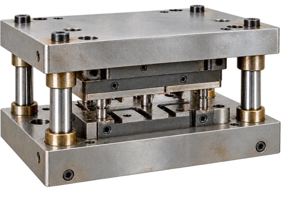
프레스 금형 이관: 도면 검토와 보수·개조가 먼저인 이유
보유한 프레스 금형을 다른 설비로 옮길 때 필요한 도면 대조, 금형 상태 조사, 보수·개조와 시타발을 살펴봅니다. 설비 차이와 남은 생산…
ID
19 10월 2026
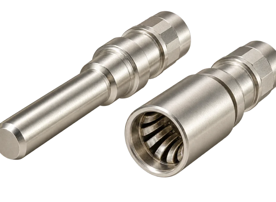
전기차 급속충전 커넥터 접점: 고전류를 받는 핀과 소켓의 구조
전기차 급속충전 커넥터 접점은 차량 인렛의 핀과 충전 플러그의 소켓이 만드는 고전류 인터페이스입니다. 눈에 잘 보이지 않는 접촉대, 도금과 케이블…
ID
18 10월 2026
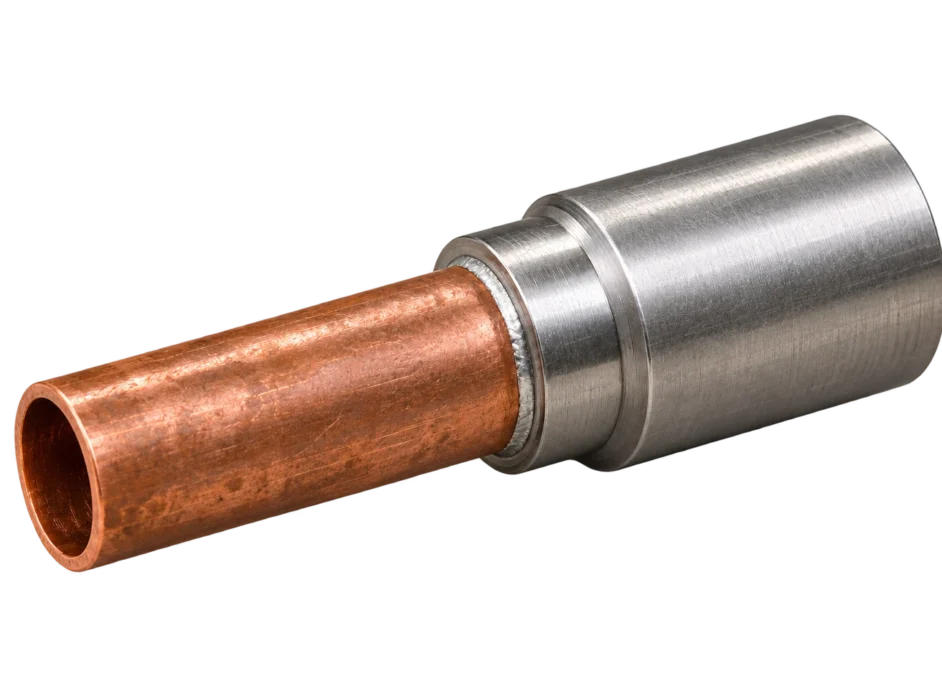
구리–스테인리스 이종 브레이징: 젖음·열간 간극·계면 내구성
구리–스테인리스 이종 브레이징 설계에서는 젖음, 열간 간극, 용가재와 공정 관리를 함께 검토해야 합니다.
ID
15 10월 2026

판금 루버 성형: 개구 형상·금형·압력손실을 연결하는 설계
루버는 판에 구멍을 많이 만드는 작업을 넘어, 절개한 재료를 원하는 방향으로 세워 공기의 통로와 패널의 구조를 함께 만드는 성형입니다.
ID
13 10월 2026
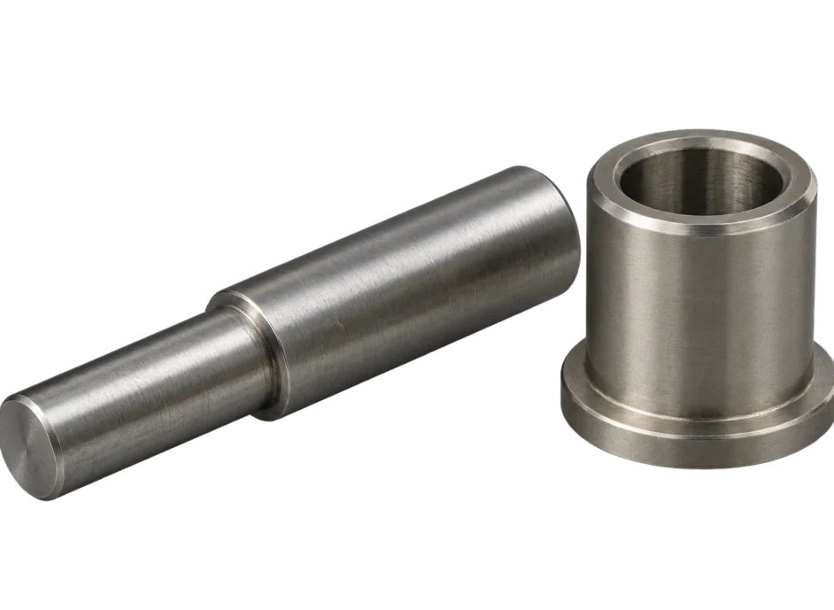
도금 공차 설계: 기능 치수·두께 분포·완성 검사
정밀 부품의 표면처리는 재료의 기능을 바꾸면서 조립 공간도 바꿉니다. 외경은 커지고 내경은 작아지며, 마스킹 경계와 국부 성장까지 상대 부품의 움직임에…