AEROSPACE MACHINING & QUALITY
항공 부품의 재료 이력·표면·해제 형상·초도품 검토
AEROSPACE MACHINING & QUALITY
얇은 벽의 지지와 표면 상태, 측정 조건을 함께 살펴봅니다.
TRACE · MACHINE · RELEASE · VERIFY
항공 부품의 가공 품질은 형상의 정확도와 그 형상을 설명할 근거를 함께 요구합니다. 재료 이력, 공정 중 강성, 해제 후 형상과 측정 조건을 연결하는 방법을 살펴봅니다.
난삭재의 가공성, 잔류응력, 표면 건전성과 초도품 검사의 적용 범위를 구분하고 실제 공정에서 확인할 항목을 정리합니다.
STRUCTURAL FEATURES / 얇은 프레임·클레비스·플랜지 슬리브
기능과 재료 이력
복잡한 형상보다 먼저 하중 전달과 요구사항의 연결을 확인합니다.
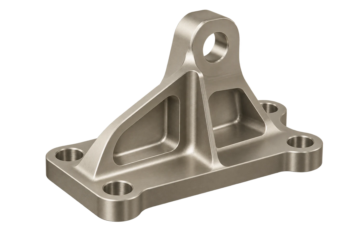
항공용 브래킷과 하우징, 링크 및 장착 부품은 외형이 비슷해도 하중 방향과 접촉 조건이 다를 수 있습니다. 얇은 리브는 무게를 줄이지만 지지 강성과 가공 중 변형에 영향을 주고, 작은 홀과 필렛은 체결 및 응력 전달의 일부가 됩니다. 도면의 중요 특성을 기능과 연결하여 어떤 형상이 가공과 검사 계획의 우선순위를 정하는지 확인합니다.
부품이 사용되는 분야만으로 공차나 검사 방식이 일률적으로 정해지지는 않습니다. 고객의 설계 자료와 계약 요구, 적용 규격과 변경 상태가 실제 판정 기준입니다. 형상 모델에는 보이지 않는 표면 처리, 모서리, 청정도와 추적 요구가 있을 수 있으므로 도면, 모델과 부가 사양을 하나의 통제된 입력으로 대조합니다.
공정 검토에서는 만들 수 있는 형상과 제출해야 할 근거를 동시에 계획합니다. 최종 단계에서 접근할 수 없는 포켓이나 교차 홀은 중간 검사가 필요할 수 있고, 처리 후 식별 표시가 사라지면 재료 이력을 유지할 대안이 필요합니다. 이러한 연결을 초기에 확인하면 제작이 끝난 뒤 검사 자료만 따로 복구하는 상황을 줄일 수 있습니다.
하중·접촉·조립 관계 · 중요 특성과 사용 조건 연결
형상 외의 요구사항 · 도면·모델·사양 개정 대조
후속 접근과 근거 · 중간 검사·추적 방법 결정
| 검토 항목 | 기술적 의미 | 검증·관리 기준 |
|---|---|---|
| 기능 형상 | 하중·접촉·조립 관계 | 중요 특성과 사용 조건 연결 |
| 설계 입력 | 형상 외의 요구사항 | 도면·모델·사양 개정 대조 |
| 검증 계획 | 후속 접근과 근거 | 중간 검사·추적 방법 결정 |
기능 형상
기술적 의미
하중·접촉·조립 관계
검증·관리 기준
중요 특성과 사용 조건 연결
설계 입력
기술적 의미
형상 외의 요구사항
검증·관리 기준
도면·모델·사양 개정 대조
검증 계획
기술적 의미
후속 접근과 근거
검증·관리 기준
중간 검사·추적 방법 결정
재질 명칭과 재료 로트의 증거는 서로 다른 정보입니다.
재료 검토는 합금 기호뿐 아니라 제품 형상, 공급 규격과 개정, 열처리 상태 및 필요한 시험 결과를 포함합니다. 같은 합금도 판재와 봉재, 단조품의 공급 조건이 다를 수 있으므로 한 자료의 값을 모든 소재에 대입하지 않습니다. 구매 요구와 재료 성적서가 일치하는지 확인하고 불일치 사항은 절삭 전에 해결하도록 관리합니다.
한 소재를 여러 블랭크로 절단하면 원래 표시와 개별 부품 사이의 연결이 끊어질 수 있습니다. 열 번호 또는 로트 식별을 절단 기록, 작업 지시와 용기 표시 등 승인된 방식으로 넘기고 혼입을 방지합니다. 식별을 위해 기능면에 임의 각인을 추가하면 표면이나 응력에 영향을 줄 수 있으므로 표시 위치와 방법도 요구사항에 맞춰 결정합니다.
추적 자료의 양이 많아도 실제 부품과 연결되지 않으면 의미가 약해집니다. 외주 처리와 재작업을 거칠 때에도 어느 제품이 어느 처리 로트를 통과했는지 확인할 수 있어야 합니다. 최종 제출 자료에는 요구된 범위의 식별 관계를 유지하고, 이 기사가 특정 업체의 재료 승인이나 공급망 자격을 보증하는 것으로 읽히지 않도록 적용 범위를 구분합니다.
합금·형상·공급 상태 · 구매 요구와 성적서 대조
절단 후 로트 연결 · 블랭크·작업 지시·용기 관리
외주와 재작업 경로 · 제품과 처리 로트 연결
재료 성적서의 존재만으로 해당 부품이 그 재료에서 제작되었다는 연결이 완성되지는 않습니다.
절단 수량과 잔여 소재, 폐기 및 재작업 수량이 기록상 연결되는지 확인합니다. 물리적 식별과 문서의 수량 관계를 함께 검토하면 혼입 조사에 도움이 됩니다.
| 검토 항목 | 기술적 의미 | 검증·관리 기준 |
|---|---|---|
| 소재 정의 | 합금·형상·공급 상태 | 구매 요구와 성적서 대조 |
| 식별 전달 | 절단 후 로트 연결 | 블랭크·작업 지시·용기 관리 |
| 처리 이력 | 외주와 재작업 경로 | 제품과 처리 로트 연결 |
소재 정의
기술적 의미
합금·형상·공급 상태
검증·관리 기준
구매 요구와 성적서 대조
식별 전달
기술적 의미
절단 후 로트 연결
검증·관리 기준
블랭크·작업 지시·용기 관리
처리 이력
기술적 의미
외주와 재작업 경로
검증·관리 기준
제품과 처리 로트 연결
난삭성과 얇은 벽
난삭재라는 한 단어로 절삭 기구를 설명할 수 없습니다.
알루미늄 합금은 얇은 구조와 큰 제거량에서 강성과 칩 배출의 균형이 중요하며, 절삭날의 용착도 표면과 치수에 영향을 줄 수 있습니다. 티타늄은 열 전달과 공구 접촉 조건을 별도로 살펴야 하고, 니켈계 합금은 소재 상태와 높은 절삭 부하에 맞는 공구 선택이 필요합니다. 재질별로 공구 등급과 날 형상, 냉각 전달 및 고정 조건을 구분해 검토합니다.
Ti-6Al-4V의 절삭 온도를 해석할 때에는 속도, 공구 상태와 관측 위치를 함께 고려합니다. 투명 공구를 이용한 직교 절삭 관찰과 실제 포켓 밀링은 형상과 공구·냉각 조건이 다르므로 한 시험의 결과를 생산용 회전수나 냉각 압력으로 직접 환산하지 않습니다. 열을 단일 대표값만으로 관리하지 않고 실제 가공 조건과 연결합니다.
티타늄 절삭에서는 채터와 공구 마모의 관계를 함께 평가합니다. 장비와 공구 조건이 바뀌면 과거의 설정을 직접 옮기지 않고 실제 재료·공구 조합으로 시험합니다. 시험 기록에는 가공 시간뿐 아니라 날 상태, 표면 흔적, 칩과 부하 변화를 함께 남겨 조건 선택의 근거를 확보합니다.
강성·칩·용착 · 구조와 공구 접촉 검토
열 전달·공구 상태 · 관측 조건과 실제 공정 구분
소재 상태·절삭 부하 · 공구 등급과 수명 시험
첫 시험에서는 재질 증명의 공급 상태와 실제 블랭크를 연결합니다. 재료 변경과 공구 변경이 겹치면 시험 구간을 구분해 결과의 원인을 추적합니다.
| 검토 항목 | 기술적 의미 | 검증·관리 기준 |
|---|---|---|
| 알루미늄 | 강성·칩·용착 | 구조와 공구 접촉 검토 |
| 티타늄 | 열 전달·공구 상태 | 관측 조건과 실제 공정 구분 |
| 니켈 합금 | 소재 상태·절삭 부하 | 공구 등급과 수명 시험 |
| 조건 검증 | 개별 조합의 재현성 | 날·칩·표면·부하 기록 |
알루미늄
기술적 의미
강성·칩·용착
검증·관리 기준
구조와 공구 접촉 검토
티타늄
기술적 의미
열 전달·공구 상태
검증·관리 기준
관측 조건과 실제 공정 구분
니켈 합금
기술적 의미
소재 상태·절삭 부하
검증·관리 기준
공구 등급과 수명 시험
조건 검증
기술적 의미
개별 조합의 재현성
검증·관리 기준
날·칩·표면·부하 기록
FILLET & WALL / 포켓 바닥과 내부 필렛, 얇은 리브
04 / THIN WALL DISTORTION
가공 중 치수와 해제 후 형상은 서로 다른 상태에서 측정됩니다.
얇은 벽을 만드는 과정에서는 소재가 제거될수록 절삭력과 고정력에 대한 구조의 응답이 달라집니다. 초기에는 단단한 블랭크였어도 마지막 리브를 정삭할 때는 지지되지 않은 판처럼 거동할 수 있습니다. 공정 순서는 최종 벽 두께만이 아니라 각 단계에 남아 있는 지지 재료와 공구 접근 방향을 고려하여 결정합니다.
알루미늄 7050 블록의 고세장비 벽을 가공할 때에는 초기 잔류응력과 가공 유발 응력의 비선형 상호작용, 공구 경로가 최종 변형에 미치는 영향을 함께 검토합니다. 특정 재료와 형상의 수치 모델을 모든 재질의 변형량으로 일반화하거나 단순한 응력 합산만으로 결과를 단정하지 않습니다.
실무에서는 대칭적인 재료 제거, 중간 안정화와 재측정, 지지 위치 또는 가공 여유 분배를 검토할 수 있습니다. 어느 방법이 유리한지는 소재 상태와 부품 형상, 설비에 따라 검증해야 하며 보편적인 대기 시간이나 절삭량 비율을 정답으로 제시하지 않습니다. 지그를 풀기 전과 후의 형상 차이를 기록하면 탄성 구속과 남은 변형을 분리하는 데 도움이 됩니다.
잔류응력 수치 모델은 실제 부품의 검사 성적서를 대신하지 않습니다.
| 검토 항목 | 기술적 의미 | 검증·관리 기준 |
|---|---|---|
| 중간 형상 | 단계별 강성 변화 | 남은 지지 재료와 경로 검토 |
| 잔류응력 | 제거에 따른 재평형 | 소재 상태와 변형 이력 연결 |
| 공구 경로 | 열·힘·제거 순서 | 시험 조건별 결과 비교 |
| 해제 상태 | 구속에서 벗어난 형상 | 고정 전후 측정 구분 |
중간 형상
기술적 의미
단계별 강성 변화
검증·관리 기준
남은 지지 재료와 경로 검토
잔류응력
기술적 의미
제거에 따른 재평형
검증·관리 기준
소재 상태와 변형 이력 연결
공구 경로
기술적 의미
열·힘·제거 순서
검증·관리 기준
시험 조건별 결과 비교
해제 상태
기술적 의미
구속에서 벗어난 형상
검증·관리 기준
고정 전후 측정 구분
절삭 위치 가까이의 지지와 공구 접근을 함께 확인합니다.
표면과 세부 형상
매끄러운 표면은 표면 아래 상태까지 설명하지 않습니다.
표면 거칠기는 형상의 미세한 높낮이를 특정 측정 조건으로 평가한 결과이며, 표면 건전성은 변형층과 잔류응력, 열 영향 및 손상 가능성까지 포함하는 더 넓은 검토입니다. 광택이 좋거나 Ra 값이 작아도 모든 기능 위험이 사라지는 것은 아닙니다. 도면과 사용 조건이 요구하는 표면 특성을 확인하고 가공 흔적, 균열 의심부와 열 변색을 구분해 조사합니다.
니켈계 구조 합금의 피로 거동을 평가할 때에는 가공으로 형성된 표면 상태를 함께 검토합니다. 특정 합금과 가공법의 결과를 다른 부품의 수명 증가율로 옮기지 않습니다. 외관이나 거칠기 하나만으로 피로와 관련된 모든 표면 상태를 대표할 수 없으므로 실제 적용 조건에 필요한 특성을 확인합니다.
공구 수명 말기에 생기는 문지름과 손상은 치수가 허용 범위 안에 있어도 추가 검토가 필요할 수 있습니다. 필요한 비파괴 검사나 금속학적 평가는 설계와 공정 요구에 따라 정의하고 자격과 방법을 확인합니다. 모든 항공 부품에 같은 검사를 추가하는 대신 어떤 결함을 어떤 단계에서 검출해야 하는지와 가공 변경의 영향을 연결합니다.
측정 조건별 표면 높낮이 · 방향·필터·평가 길이 확인
열·마찰·날 손상의 흔적 · 위치와 공구 이력 연결
변형층·잔류응력 가능성 · 요구된 평가 방법 검토
표면 이상을 발견하면 임의로 연마하여 흔적을 지우기 전에 위치와 상태를 기록합니다. 수정으로 형상이나 표면 상태가 바뀌는 범위를 승인된 절차에서 검토합니다.
| 검토 항목 | 기술적 의미 | 검증·관리 기준 |
|---|---|---|
| 거칠기 | 측정 조건별 표면 높낮이 | 방향·필터·평가 길이 확인 |
| 표면 손상 | 열·마찰·날 손상의 흔적 | 위치와 공구 이력 연결 |
| 표면 아래 | 변형층·잔류응력 가능성 | 요구된 평가 방법 검토 |
| 검사 선택 | 검출할 결함의 범위 | 사양·단계·자격 확인 |
거칠기
기술적 의미
측정 조건별 표면 높낮이
검증·관리 기준
방향·필터·평가 길이 확인
표면 손상
기술적 의미
열·마찰·날 손상의 흔적
검증·관리 기준
위치와 공구 이력 연결
표면 아래
기술적 의미
변형층·잔류응력 가능성
검증·관리 기준
요구된 평가 방법 검토
검사 선택
기술적 의미
검출할 결함의 범위
검증·관리 기준
사양·단계·자격 확인
작은 마무리 형상도 접촉과 조립 상태를 바꿀 수 있습니다.
체결 홀은 직경뿐 아니라 패턴의 위치와 축 방향, 유효 접촉 길이를 함께 검토합니다. 얇은 벽 가까이에 있는 홀은 주변 재료의 지지가 부족할 수 있고, 카운터보어의 깊이는 남은 벽 두께와 볼트 머리 안착에 영향을 줍니다. 홀 가공과 모서리 처리의 순서가 최종 접촉을 어떻게 바꾸는지 확인하고 후속 코팅의 영향도 포함합니다.
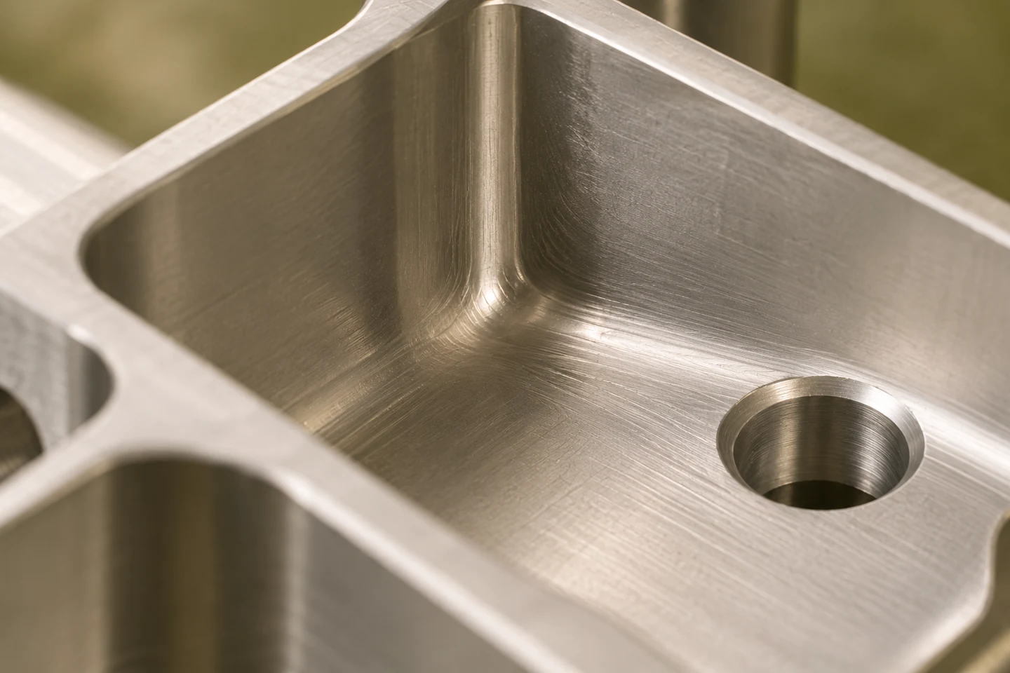
포켓 내부 필렛은 공구 접근과 구조적 전이를 함께 고려하는 형상입니다. 작은 반경을 요구하면 더 작은 공구와 긴 돌출이 필요해 가공 안정성이 달라질 수 있습니다. 설계 변경이 가능한지 문의할 때에는 단순히 가공이 어렵다는 이유보다 기능면과 여유 공간, 공구 경로 및 검사 접근의 차이를 명확히 제시합니다.
버 제거는 형상의 일부를 추가로 제거하는 작업이므로 날카로운 모서리를 모두 크게 둥글게 만드는 것과 같지 않습니다. 허용 모서리와 챔퍼, 잔류 버 기준을 확인하고 접근이 어려운 교차부는 검사 방법을 따로 정합니다. 과도한 수작업 연마는 접촉 길이와 홀 크기를 바꿀 수 있어 작업 후에도 요구 형상이 유지되는지 확인해야 합니다.
체결과 축의 관계 · 위치·방향·접촉 길이 확인
머리 안착과 잔여 벽 · 깊이·벽 두께·처리 영향 검토
구조 전이와 접근성 · 반경·공구 돌출·검사 비교
접근하기 어려운 부위는 최종 사진만으로 확인 가능한지 검토합니다. 시야가 막히기 전 검사와 후속 청정도 확인을 공정 순서에 배치합니다.
| 검토 항목 | 기술적 의미 | 검증·관리 기준 |
|---|---|---|
| 홀 패턴 | 체결과 축의 관계 | 위치·방향·접촉 길이 확인 |
| 카운터보어 | 머리 안착과 잔여 벽 | 깊이·벽 두께·처리 영향 검토 |
| 내부 필렛 | 구조 전이와 접근성 | 반경·공구 돌출·검사 비교 |
| 모서리 | 접촉과 잔류물 관리 | 허용 형상·버·수정 범위 확인 |
홀 패턴
기술적 의미
체결과 축의 관계
검증·관리 기준
위치·방향·접촉 길이 확인
카운터보어
기술적 의미
머리 안착과 잔여 벽
검증·관리 기준
깊이·벽 두께·처리 영향 검토
내부 필렛
기술적 의미
구조 전이와 접근성
검증·관리 기준
반경·공구 돌출·검사 비교
모서리
기술적 의미
접촉과 잔류물 관리
검증·관리 기준
허용 형상·버·수정 범위 확인
SUPPORTED PROBING / 두꺼운 기저부 지지와 측면 접촉 탐침
계측 지그와 제거율
검사 지그가 형상을 바꾸지 않는지 함께 확인합니다.
얇은 브래킷을 위치 결정할 때는 설계 기준을 재현하는 접촉과 측정 중 처짐을 제한하는 보조 지지를 구분합니다. 보조 지지의 높이를 잘못 맞추면 부품을 들어 올리거나 비틀 수 있고, 클램프 힘이 크면 자유 상태와 다른 형상을 만들 수 있습니다. 도면이 구속 상태를 요구하는지 자유 상태를 요구하는지 확인한 뒤 지지와 측정 조건을 정합니다.
CMM 탐침은 측정 면에 접근할 수 있어야 하고 가느다란 리브를 밀어 변형시키지 않도록 접촉 조건을 검토해야 합니다. 탐침 길이와 자세, 접촉 위치와 샘플링은 실제 형상에 맞춰 정하며 접근 가능한 몇 점이 표면 전체를 대표한다고 가정하지 않습니다. 검사 프로그램에는 기준 설정용 접촉과 평가 특성용 접촉의 역할을 구분합니다.
계측 지그의 3D 순서는 위치 결정, 지지 상태의 프로빙, 고정 해제 후 형상, 특성 검토의 네 상태를 보여줍니다. 이 구분은 실제 변형량이나 합격 결과를 표시하기 위한 것이 아니라 같은 부품도 구속 상태에 따라 측정의 의미가 달라짐을 설명합니다. 실제 검증에서는 상태 전환 전후의 식별과 동일한 평가 기준을 유지해야 비교가 가능합니다.
설계 기준의 재현 · 접촉 우선순위와 안착 확인
측정 중 처짐의 제한 · 높이·접촉·과구속 검토
실제 표면의 표본화 · 접촉력·접근·분포 확인
자유 상태 형상을 지그로 눌러 맞춘 뒤 측정하면 도면 의도와 다른 결과가 될 수 있습니다.
검사 지그의 사진과 설정값에는 보조 지지의 접촉 순서도 남깁니다. 측정 중 지지 위치를 바꾸었다면 해당 결과의 조건이 달라졌음을 기록합니다.
| 검토 항목 | 기술적 의미 | 검증·관리 기준 |
|---|---|---|
| 위치 결정 | 설계 기준의 재현 | 접촉 우선순위와 안착 확인 |
| 보조 지지 | 측정 중 처짐의 제한 | 높이·접촉·과구속 검토 |
| 프로빙 | 실제 표면의 표본화 | 접촉력·접근·분포 확인 |
| 해제 비교 | 구속 영향의 확인 | 같은 기준과 상태 기록 |
위치 결정
기술적 의미
설계 기준의 재현
검증·관리 기준
접촉 우선순위와 안착 확인
보조 지지
기술적 의미
측정 중 처짐의 제한
검증·관리 기준
높이·접촉·과구속 검토
프로빙
기술적 의미
실제 표면의 표본화
검증·관리 기준
접촉력·접근·분포 확인
해제 비교
기술적 의미
구속 영향의 확인
검증·관리 기준
같은 기준과 상태 기록
부품을 들어 올려 구속 해제 상태를 구분합니다. 이동량은 실제 변형값이 아닙니다.
많이 깎는 속도는 최종 형상과 표면의 보증값이 아닙니다.
밀링의 명목 제거율은 축 방향 절입 깊이와 반경 방향 절입 폭, 분당 이송을 곱해 계산할 수 있습니다. 이 관계는 절삭에 참여하는 단면이 일정한 구간의 생산성을 비교하는 데 유용하지만 포켓 진입, 코너와 가감속 구간에서는 순간 조건이 달라집니다. 전체 사이클 시간에는 공구 이동과 교환, 검사 및 세척도 포함하여 비교합니다.
가정한 절입 깊이 2 mm, 절입 폭 5 mm, 분당 이송 300 mm/min이면 명목 제거율은 3 cm³/min입니다. 이는 단위 환산을 보여주는 예일 뿐 항공 합금에 적합한 가공 조건을 권장하지 않습니다. 같은 제거율도 절입과 이송의 조합에 따라 날의 하중, 열 분포와 얇은 벽에 작용하는 힘이 달라질 수 있습니다.
제거율을 높이는 제안은 공구 수명과 표면 상태, 해제 후 변형 및 검사 결과를 함께 검증합니다. 황삭에서 유리한 조건이 마지막 얇은 벽 정삭에 적합하다고 가정하지 않습니다. 프로그램의 절삭 구간을 기능별로 나누고 소재 상태와 지지 조건이 바뀌는 위치에서 조건을 재검토하면 생산성과 형상 유지의 관계를 설명할 수 있습니다.
Q: 명목 재료 제거율 [cm³/min], a_p: 축 방향 절입 깊이 [mm], a_e: 반경 방향 절입 폭 [mm], v_f: 분당 이송 [mm/min]. 일정 단면의 정상 절삭 근사이며 진입·코너·가감속·공구 마모·열·변형과 전체 사이클 시간을 예측하지 않습니다.
견적 비교에서는 절삭 시간 감소와 추가 검사·공구 교환 시간을 함께 봅니다. 한 구간의 생산성 개선이 전체 제작 흐름에서 유지되는지 확인합니다.
| 검토 항목 | 기술적 의미 | 검증·관리 기준 |
|---|---|---|
| 절입 깊이 | 축 방향 참여 길이 | 실제 접촉 구간 확인 |
| 절입 폭 | 반경 방향 맞물림 | 코너와 진입 변화 검토 |
| 분당 이송 | 경로의 진행 속도 | 가감속과 유효 날 조건 확인 |
| 공정 검증 | 제거율 밖의 품질 | 수명·표면·해제 형상 평가 |
절입 깊이
기술적 의미
축 방향 참여 길이
검증·관리 기준
실제 접촉 구간 확인
절입 폭
기술적 의미
반경 방향 맞물림
검증·관리 기준
코너와 진입 변화 검토
분당 이송
기술적 의미
경로의 진행 속도
검증·관리 기준
가감속과 유효 날 조건 확인
공정 검증
기술적 의미
제거율 밖의 품질
검증·관리 기준
수명·표면·해제 형상 평가
측정과 초도품
계측 장비의 이름보다 측정 과정의 정의가 먼저입니다.
포켓 깊이와 벽 두께, 홀 위치와 면 윤곽은 서로 다른 접촉과 기준 정렬을 필요로 합니다. CMM 한 번으로 모든 요구를 검사할 수 있다고 가정하지 말고 거칠기, 모서리와 청정도 등 다른 방법이 필요한 항목을 식별합니다. 검사 계획은 각 특성을 어떤 상태에서 어떤 장비와 방법으로 평가하는지 명시하여 결과의 해석 범위를 분명히 합니다.
긴 부품이나 온도에 민감한 측정에서는 부품과 기준기, 장비의 온도 차이를 검토합니다. 열팽창 보정은 재질의 계수와 온도 측정의 불확실성을 포함하므로 실내가 정해진 온도라는 이유만으로 영향이 사라지지 않습니다. 가공 직후와 안정화 후의 자료를 섞지 않고 측정 당시의 조건을 부품 식별과 함께 남깁니다.
반복성과 재현성 검토는 측정기 표시 자릿수와 별개입니다. 탐침 교환이나 검사 프로그램 개정, 지그 변경이 결과를 바꿀 수 있으므로 변경 사건을 관리합니다. 샘플링 점이 적은 측정은 국부 형상 이상을 놓칠 수 있어 예상되는 오차 형태와 기능 영역을 고려하여 점 분포와 검사 밀도를 정합니다.
표본 점이 늘었다는 사실만으로 적절한 기준 정렬이나 측정 불확도가 확보되지는 않습니다.
검사 프로그램 검토에는 실제 탐침 경로와 접근 불가능한 영역을 표시합니다. 모델 전체를 검사한 것처럼 보고하지 않고 평가하지 않은 범위를 명확히 남깁니다.
| 검토 항목 | 기술적 의미 | 검증·관리 기준 |
|---|---|---|
| 특성별 방법 | 서로 다른 평가 대상 | 치수·형상·거칠기 구분 |
| 온도 조건 | 길이와 보정의 영향 | 부품·기준기·시간 기록 |
| 측정 변경 | 결과의 연속성 | 탐침·프로그램·지그 이력 |
| 표본 분포 | 국부 이상 검출 가능성 | 기능 영역과 오차 형태 반영 |
특성별 방법
기술적 의미
서로 다른 평가 대상
검증·관리 기준
치수·형상·거칠기 구분
온도 조건
기술적 의미
길이와 보정의 영향
검증·관리 기준
부품·기준기·시간 기록
측정 변경
기술적 의미
결과의 연속성
검증·관리 기준
탐침·프로그램·지그 이력
표본 분포
기술적 의미
국부 이상 검출 가능성
검증·관리 기준
기능 영역과 오차 형태 반영
초도품 검사는 고객과 적용 규격의 요구를 보완하는 검증 체계입니다.
AS9102C의 공식 공개 범위는 항공 분야 초도품 검사를 수행하고 문서화하기 위한 요구를 설명합니다. 공개 설명은 이 요구가 고객 및 적용 법규 요구의 대체가 아니라 보완임을 명확히 합니다. 유료 표준의 세부 조항을 열람하지 않은 상태에서 특정 양식이나 전면·부분 수행 조건을 임의로 단정하지 않고 계약에서 지정한 판본과 절차를 확인합니다.
FAI 준비에서는 승인된 설계 특성과 제작·검사 결과를 연결하고 자료의 개정 상태와 제품 식별이 일치하는지 확인합니다. 재료와 처리 증빙, 치수 결과 및 요구된 기능 시험은 서로 다른 증거이므로 각각의 출처와 평가 범위를 유지합니다. 문서가 완성되었다는 사실만으로 모든 생산품이 동일하게 적합하다고 결론내리지 않습니다.
공급망 전반에서 일관된 초도품 검증이 필요합니다. 실제 적용 범위와 제출 방식, 변경 시 재평가 여부는 계약과 적용 절차에 따라 정해야 합니다. 이 글에서 FAI를 설명하는 것은 아이디솔루텍의 항공 품질 인증이나 특정 고객 승인을 주장하는 것이 아니며 개별 프로젝트에서 필요한 검증 논의를 돕기 위한 것입니다.
계약과 규격의 관계 · 판본·절차·제출 요구 확인
설계와 결과의 대응 · 개정·식별·측정 근거 대조
재료·처리·치수·기능 · 각 자료의 출처와 범위 유지
초도품 검토 전에 미충족 또는 미확정 요구를 목록화하고 처리 책임과 완료 근거를 정합니다. 빈칸을 관행적으로 채우는 대신 설계 요구와 증거의 연결을 확인합니다.
| 검토 항목 | 기술적 의미 | 검증·관리 기준 |
|---|---|---|
| 적용 범위 | 계약과 규격의 관계 | 판본·절차·제출 요구 확인 |
| 특성 연결 | 설계와 결과의 대응 | 개정·식별·측정 근거 대조 |
| 증거 구분 | 재료·처리·치수·기능 | 각 자료의 출처와 범위 유지 |
| 변경 검토 | 재평가 필요성 | 계약과 승인 절차에 따라 판단 |
적용 범위
기술적 의미
계약과 규격의 관계
검증·관리 기준
판본·절차·제출 요구 확인
특성 연결
기술적 의미
설계와 결과의 대응
검증·관리 기준
개정·식별·측정 근거 대조
증거 구분
기술적 의미
재료·처리·치수·기능
검증·관리 기준
각 자료의 출처와 범위 유지
변경 검토
기술적 의미
재평가 필요성
검증·관리 기준
계약과 승인 절차에 따라 판단
변경 관리와 개발
같은 프로그램 번호라도 제작 조건이 바뀔 수 있습니다.
공구 공급처와 코팅, 날 형상 또는 재연마 상태가 바뀌면 공정의 열과 힘, 표면 상태가 달라질 수 있습니다. 지그 지지 위치와 클램프 순서, 냉각 전달이나 소재 공급 상태도 같은 수준으로 검토해야 합니다. 변경 전후에 무엇이 달라졌는지 기록하고 영향받는 특성 및 재검증 범위를 정해 좋은 결과만 선택적으로 비교하지 않습니다.
얇은 벽의 경우 공정 변경이 치수에는 작게 나타나도 해제 후 형상이나 표면 흔적에서 먼저 보일 수 있습니다. 공구 수명 순서와 가공 부하, 표면 관찰 및 측정을 연결하면 이런 변화를 놓치지 않는 데 도움이 됩니다. 관리 항목은 해당 부품의 위험과 변동 원인에 맞춰 정하고 모든 부품에 동일한 검사 간격을 일괄 적용하지 않습니다.
부적합을 발견하면 임의 보정과 재가공에 앞서 영향 제품을 식별하고 승인된 처리 경로를 따릅니다. 추가 절삭은 벽 두께와 필렛, 코팅 상태 및 검사 가능성을 바꿀 수 있으므로 원래 치수 하나만 맞추는 것으로 판단하지 않습니다. 변경 후 생산을 재개할 조건과 제출 자료의 개정 필요성을 공정 책임자와 검사 기준에 연결합니다.
열·힘·표면의 변화 · 등급·형상·수명 조건 대조
구속과 해제 형상 · 접촉·힘·순서 검증
영향 제품의 식별 · 변경 시점과 로트 연결
공구 품번이 같아도 조립 길이와 냉각 전달이 달라지면 동일한 절삭 조건으로 볼 수 없습니다.
변경 기록에는 승인 시점과 실제 적용 시점을 구별합니다. 첫 적용 제품을 식별하면 문서의 개정과 생산 현장의 전환 사이 공백을 확인할 수 있습니다.
| 검토 항목 | 기술적 의미 | 검증·관리 기준 |
|---|---|---|
| 공구 변경 | 열·힘·표면의 변화 | 등급·형상·수명 조건 대조 |
| 지지 변경 | 구속과 해제 형상 | 접촉·힘·순서 검증 |
| 이상 구간 | 영향 제품의 식별 | 변경 시점과 로트 연결 |
| 재작업 검토 | 남은 기능과 근거 | 벽·필렛·처리·재검사 확인 |
공구 변경
기술적 의미
열·힘·표면의 변화
검증·관리 기준
등급·형상·수명 조건 대조
지지 변경
기술적 의미
구속과 해제 형상
검증·관리 기준
접촉·힘·순서 검증
이상 구간
기술적 의미
영향 제품의 식별
검증·관리 기준
변경 시점과 로트 연결
재작업 검토
기술적 의미
남은 기능과 근거
검증·관리 기준
벽·필렛·처리·재검사 확인
가공 조건과 품질 자료는 같은 요구사항에서 출발해야 합니다.
개발 검토 자료에는 관리 도면과 모델, 소재 공급 규격과 상태, 기능 특성, 처리 요구와 수량·일정을 포함합니다. 얇은 벽이나 접근이 어려운 내부 형상은 설계 의도와 검사 허용 상태를 설명하면 검토가 구체적입니다. 미확정 요구를 빈칸으로 남기기보다 담당자와 확정 시점을 표시하여 공구와 지그를 만들기 전에 해결할 항목을 구분합니다.
공정 제안은 재료 식별, 기준 가공, 황삭과 정삭, 모서리 처리, 외주 공정 및 검사 자료의 흐름으로 비교합니다. 필요하면 중간 시제품으로 지지와 해제 형상, 표면 및 측정 접근을 확인하고 생산 전환에 필요한 근거를 정합니다. 시제품 한 개의 합격을 장기 생산 능력으로 확대 해석하지 않고 실제 조건 변화에 따른 재검토 범위를 합의합니다.
아이디솔루텍과 협의할 때에는 FAI 또는 별도 고객 양식, 추적 수준과 검사 제출물을 명확히 전달하면 일정과 검토 범위를 맞추기 쉽습니다. 여기의 기술 설명과 사진은 부품 형상과 검증 방법을 설명하며 특정 공장, 인증, 승인이나 성능 결과의 증거가 아닙니다. 실제 제작과 품질 보증의 범위는 계약과 승인된 기술 요구사항에 따라 확정합니다.
제작과 검증의 기준 · 도면·소재·처리·기능 정리
불확실한 공정 관계 · 지지·표면·측정 접근 확인
조건 변화의 관리 · 검증 범위와 변경 기준 합의
최종 검토에서는 제작 경로와 자료 제출 경로를 같은 제품 식별로 따라갑니다. 형상은 완성되었지만 증거가 끊어진 지점을 출하 이전에 찾을 수 있습니다.
| 검토 항목 | 기술적 의미 | 검증·관리 기준 |
|---|---|---|
| 개발 입력 | 제작과 검증의 기준 | 도면·소재·처리·기능 정리 |
| 시험 목적 | 불확실한 공정 관계 | 지지·표면·측정 접근 확인 |
| 생산 전환 | 조건 변화의 관리 | 검증 범위와 변경 기준 합의 |
| 제출 요구 | 일정과 근거의 연결 | FAI·추적·성적서 명시 |
개발 입력
기술적 의미
제작과 검증의 기준
검증·관리 기준
도면·소재·처리·기능 정리
시험 목적
기술적 의미
불확실한 공정 관계
검증·관리 기준
지지·표면·측정 접근 확인
생산 전환
기술적 의미
조건 변화의 관리
검증·관리 기준
검증 범위와 변경 기준 합의
제출 요구
기술적 의미
일정과 근거의 연결
검증·관리 기준
FAI·추적·성적서 명시
관리 도면과 모델, 소재 규격·상태, 기능·처리 조건, 수량·일정과 FAI·추적·검사 요구를 보내주세요. 제작 경로와 검증 근거를 함께 검토합니다.
Provide controlled drawings and models, stock specification and condition, function and finish, volume, schedule and FAI, traceability and inspection requirements. Review the route and evidence together.
AEROSPACE MACHINING & QUALITY
Review thin-wall support, surface state and measurement conditions together.
TRACE · MACHINE · RELEASE · VERIFY
ENGLISH EDITION
An engineering connection from material to final characteristics.
Aerospace machining quality connects accurate geometry with evidence explaining how it was produced and verified. Follow material identity, in-process stiffness, released shape and measurement conditions.
Define the applicable scope of machinability, residual stress, surface integrity and first article inspection, then identify the checks needed for the actual process.
STRUCTURAL FEATURES / Thin frame, clevis and flanged sleeve
Function and material identity
Connect load paths and requirements before focusing on geometric complexity.
Aerospace brackets, housings, links and mounts can look similar while carrying different loads and contacts. Thin ribs reduce mass but affect support and machining deformation; holes and fillets participate in fastening and stress transfer. Link significant drawing characteristics to function before prioritizing machining and inspection.
The application sector alone does not impose one tolerance or inspection method. Customer design data, contract requirements, applicable specifications and revision status govern acceptance. Compare drawings, models and supplemental requirements as controlled inputs, including finish, edges, cleanliness and traceability absent from geometry.
Plan manufacturable geometry and required evidence together. Inaccessible pockets or intersecting holes may need intermediate inspection; identification removed during processing needs a traceability alternative. Early coordination avoids trying to reconstruct an evidence package after manufacturing is complete.
Load, contact and assembly. Connect characteristics to service
Requirements beyond shape. Align drawing, model and specification
Later access and evidence. Plan intermediate checks and traceability
| Review item | Engineering significance | Verification or control |
|---|---|---|
| Functional geometry | Load, contact and assembly | Connect characteristics to service |
| Design inputs | Requirements beyond shape | Align drawing, model and specification |
| Validation plan | Later access and evidence | Plan intermediate checks and traceability |
Functional geometry
Engineering significance
Load, contact and assembly
Verification or control
Connect characteristics to service
Design inputs
Engineering significance
Requirements beyond shape
Verification or control
Align drawing, model and specification
Validation plan
Engineering significance
Later access and evidence
Verification or control
Plan intermediate checks and traceability
An alloy designation and evidence of material identity are different information.
Review product form, supply specification and revision, temper and required test results as well as alloy designation. Plate, bar and forgings of one alloy can have different supply conditions. Reconcile purchase requirements with material certification and resolve discrepancies before cutting.
Cutting one stock piece into several blanks can break the connection to its original identification. Transfer heat or lot identity through approved cutting records, travelers or containers and prevent mixing. Do not add arbitrary marks on functional surfaces; determine marking location and method against requirements.
Extensive records have limited value without a link to the actual part. Preserve that connection through outsourced processing and rework. Deliver the required identification relationships without implying that this article establishes a supplier’s material approval or supply-chain qualification.
Alloy, form and supply condition. Compare purchase and certification
Lot link after cutting. Control blanks, travelers and containers
Outsourcing and rework route. Link parts to treatment lots
A material certificate alone does not complete the link between that material and the finished part.
Reconcile cut quantities, remaining stock, scrap and rework with identification records to support investigations of possible material mixing.
| Review item | Engineering significance | Verification or control |
|---|---|---|
| Stock definition | Alloy, form and supply condition | Compare purchase and certification |
| Identity transfer | Lot link after cutting | Control blanks, travelers and containers |
| Process history | Outsourcing and rework route | Link parts to treatment lots |
Stock definition
Engineering significance
Alloy, form and supply condition
Verification or control
Compare purchase and certification
Identity transfer
Engineering significance
Lot link after cutting
Verification or control
Control blanks, travelers and containers
Process history
Engineering significance
Outsourcing and rework route
Verification or control
Link parts to treatment lots
Machinability and thin walls
One difficult-material label cannot describe every cutting mechanism.
For aluminum structures with thin walls and substantial removal, stiffness, chip evacuation and edge adhesion can govern outcomes. Titanium requires distinct attention to heat transfer and contact; nickel alloys require tooling suited to stock condition and cutting load. Review grade, geometry, fluid delivery and holding by alloy.
Interpret Ti-6Al-4V cutting temperature together with speed, tool condition and observation position. Transparent-tool orthogonal cutting and pocket milling have different geometry, tooling and cooling conditions, so one test does not establish production rpm or coolant pressure. Connect temperature assessment to the actual cutting conditions rather than a single context-free value.
Evaluate chatter and tool wear together in titanium cutting. When equipment or tooling changes, trial the actual material–tool combination rather than transferring historical settings directly. Retain edge condition, surface marks, chips and load alongside machining time.
Stiffness, chips and adhesion. Review structure and edge contact
Heat transfer and tool condition. Validate observations in the actual process
Stock condition and cutting load. Trial tool grade and life
Link certified stock condition to the trial blank and separate trial intervals when material and tooling changes overlap.
| Review item | Engineering significance | Verification or control |
|---|---|---|
| Aluminum | Stiffness, chips and adhesion | Review structure and edge contact |
| Titanium | Heat transfer and tool condition | Validate observations in the actual process |
| Nickel alloys | Stock condition and cutting load | Trial tool grade and life |
| Condition validation | Repeatability of the actual combination | Record edge, chip, surface and load |
Aluminum
Engineering significance
Stiffness, chips and adhesion
Verification or control
Review structure and edge contact
Titanium
Engineering significance
Heat transfer and tool condition
Verification or control
Validate observations in the actual process
Nickel alloys
Engineering significance
Stock condition and cutting load
Verification or control
Trial tool grade and life
Condition validation
Engineering significance
Repeatability of the actual combination
Verification or control
Record edge, chip, surface and load
FILLET & WALL / Pocket floor, internal fillet and thin rib
04 / THIN WALL DISTORTION
In-process size and released geometry are measured in different states.
As material is removed, a thin-wall structure responds differently to cutting and holding forces. A stiff blank can become an unsupported plate by the last rib finish. Plan each stage around remaining support material and cutter direction, not only final wall thickness.
When machining high-aspect-ratio walls in aluminum 7050 blocks, evaluate nonlinear interaction between inherent and machining-induced residual stresses together with the tool-path effect on final distortion. A model for one material and geometry does not provide universal deformation values or justify simple stress-superposition assumptions.
Potential strategies include balanced removal, intermediate stabilization and measurement, support changes and allowance distribution. Validate them for stock, geometry and equipment rather than prescribing one waiting time or removal ratio. Comparing held and released geometry helps separate elastic restraint from remaining distortion.
A residual-stress simulation does not replace inspection of the actual component.
| Review item | Engineering significance | Verification or control |
|---|---|---|
| Intermediate geometry | Changing stiffness by stage | Review support stock and paths |
| Residual stress | Redistribution during removal | Link stock condition and distortion history |
| Tool path | Heat, force and removal sequence | Compare results by trial conditions |
| Released state | Geometry outside restraint | Separate held and released readings |
Intermediate geometry
Engineering significance
Changing stiffness by stage
Verification or control
Review support stock and paths
Residual stress
Engineering significance
Redistribution during removal
Verification or control
Link stock condition and distortion history
Tool path
Engineering significance
Heat, force and removal sequence
Verification or control
Compare results by trial conditions
Released state
Engineering significance
Geometry outside restraint
Verification or control
Separate held and released readings
Review support near the cut together with tool access.
Surfaces and detailed features
A smooth appearance does not characterize the subsurface.
Roughness measures fine surface-height variation under specified conditions; surface integrity also considers affected layers, residual stress, thermal effects and damage. Shine or a low Ra does not remove every functional risk. Identify required characteristics and distinguish machining marks, suspected cracks and thermal discoloration.
Machining-related surface states can affect fatigue in nickel structural alloys. Effects established for particular alloys and processes do not support a life-improvement percentage for another part. Evaluate fatigue-related surface conditions beyond appearance and roughness alone.
Rubbing or damage near the end of tool life can require review even while dimensions remain within limits. Define any nondestructive or metallurgical evaluation from design and process requirements, including method and qualification. Connect the defect to detect, inspection stage and effect of process changes.
Surface height under defined conditions. Check direction, filtering and length
Evidence of heat, rubbing or edge damage. Link location and tool history
Affected layers and residual stress. Review required evaluation methods
Record the location and condition before polishing away a surface indication; review the geometric and surface effects of correction through the approved route.
| Review item | Engineering significance | Verification or control |
|---|---|---|
| Roughness | Surface height under defined conditions | Check direction, filtering and length |
| Surface damage | Evidence of heat, rubbing or edge damage | Link location and tool history |
| Subsurface state | Affected layers and residual stress | Review required evaluation methods |
| Inspection selection | Defect-detection scope | Check specification, stage and qualification |
Roughness
Engineering significance
Surface height under defined conditions
Verification or control
Check direction, filtering and length
Surface damage
Engineering significance
Evidence of heat, rubbing or edge damage
Verification or control
Link location and tool history
Subsurface state
Engineering significance
Affected layers and residual stress
Verification or control
Review required evaluation methods
Inspection selection
Engineering significance
Defect-detection scope
Verification or control
Check specification, stage and qualification
Small finishing features can change contact and assembly behavior.
Fastener holes require position, axis direction and effective contact length as well as diameter. Holes near thin walls can lack support, while counterbore depth affects remaining wall and head seating. Review the effect of hole and edge-operation sequence and subsequent coatings on final contact.
Internal fillets combine structural transition with cutter access. Smaller radii may require smaller tools and greater overhang, altering stability. When proposing a design change, explain effects on function, clearance, tool path and inspection rather than citing machining difficulty alone.
Deburring removes additional material and is not equivalent to rounding every edge generously. Establish permitted edges, chamfers and residual burr criteria, with separate methods for inaccessible intersections. Check that manual finishing preserves contact length and hole geometry.
Fastening and axis relationship. Check position, direction and contact length
Head seating and remaining wall. Review depth, wall and finishing effects
Structural transition and access. Compare radius, projection and inspection
Assess whether final photographs can actually reveal difficult areas and schedule inspection before access is obstructed, followed by required cleanliness checks.
| Review item | Engineering significance | Verification or control |
|---|---|---|
| Hole patterns | Fastening and axis relationship | Check position, direction and contact length |
| Counterbores | Head seating and remaining wall | Review depth, wall and finishing effects |
| Internal fillets | Structural transition and access | Compare radius, projection and inspection |
| Edges | Contact and residue control | Check permitted form, burrs and correction |
Hole patterns
Engineering significance
Fastening and axis relationship
Verification or control
Check position, direction and contact length
Counterbores
Engineering significance
Head seating and remaining wall
Verification or control
Review depth, wall and finishing effects
Internal fillets
Engineering significance
Structural transition and access
Verification or control
Compare radius, projection and inspection
Edges
Engineering significance
Contact and residue control
Verification or control
Check permitted form, burrs and correction
SUPPORTED PROBING / Thick-base support and lateral contact stylus
Inspection restraint and removal rate
Review whether the inspection fixture changes the geometry it measures.
For a thin bracket, distinguish contacts reproducing design datums from auxiliary supports limiting sag during measurement. Incorrect support height can lift or twist the part, and clamping can impose a shape different from the free state. Determine whether the drawing requires restrained or free-state evaluation before defining the setup.
Review CMM access and contact conditions so the stylus does not deflect a slender rib. Select length, orientation, locations and sampling for the actual geometry; a few accessible points do not automatically represent a whole surface. Separate datum-establishing contacts from evaluated-characteristic contacts.
The fixture model shows locating, supported probing, released geometry and characteristic review. These states explain how restraint changes measurement meaning, rather than displaying actual deformation or acceptance results. Preserve identity and evaluation criteria across state changes for a valid comparison.
Reproduction of design references. Check contact order and seating
Limiting sag during measurement. Review height, contact and overconstraint
Sampling the actual surface. Check force, access and distribution
Pressing a free-state feature into nominal shape for measurement can defeat the drawing intent.
Record auxiliary-support contact sequence with fixture photographs and settings; note any support changes that alter measurement conditions.
| Review item | Engineering significance | Verification or control |
|---|---|---|
| Location | Reproduction of design references | Check contact order and seating |
| Auxiliary support | Limiting sag during measurement | Review height, contact and overconstraint |
| Probing | Sampling the actual surface | Check force, access and distribution |
| Release comparison | Assessment of restraint effects | Retain common criteria and state records |
Location
Engineering significance
Reproduction of design references
Verification or control
Check contact order and seating
Auxiliary support
Engineering significance
Limiting sag during measurement
Verification or control
Review height, contact and overconstraint
Probing
Engineering significance
Sampling the actual surface
Verification or control
Check force, access and distribution
Release comparison
Engineering significance
Assessment of restraint effects
Verification or control
Retain common criteria and state records
The raised part distinguishes release from restraint; travel is not measured distortion.
A high removal rate does not guarantee final geometry or surface condition.
Nominal milling removal rate is axial depth multiplied by radial width and feed rate. It is useful for comparing steady engaged sections, but entry, corners and acceleration change instantaneous conditions. Include travel, tool changes, inspection and cleaning when comparing complete cycle time.
An illustrative depth of 2 mm, width of 5 mm and feed of 300 mm/min gives 3 cm³/min. This is a unit-conversion example, not a cutting recommendation for an aerospace alloy. Equal removal rates can produce different tooth loads, heat distributions and forces on thin walls.
Validate increased removal rate against tool life, surface state, released distortion and inspection. A useful roughing condition need not suit final thin-wall finishing. Separate program segments by function and revisit conditions where stock and support change.
Q: nominal material removal rate [cm³/min]; a_p: axial depth [mm]; a_e: radial width [mm]; v_f: feed rate [mm/min]. Approximation for steady engagement of constant section; it does not predict entry, corners, acceleration, wear, heat, distortion or total cycle time.
Compare reduced cutting time with added inspection and tool-change time to determine whether a local productivity gain survives across the full route.
| Review item | Engineering significance | Verification or control |
|---|---|---|
| Axial depth | Axial engagement length | Check actual cutting segment |
| Radial width | Radial immersion | Review corner and entry changes |
| Feed rate | Progress along the path | Check acceleration and tooth conditions |
| Process validation | Quality beyond removal rate | Evaluate life, surface and released shape |
Axial depth
Engineering significance
Axial engagement length
Verification or control
Check actual cutting segment
Radial width
Engineering significance
Radial immersion
Verification or control
Review corner and entry changes
Feed rate
Engineering significance
Progress along the path
Verification or control
Check acceleration and tooth conditions
Process validation
Engineering significance
Quality beyond removal rate
Verification or control
Evaluate life, surface and released shape
Measurement and first article
Define the measurement process before relying on an instrument name.
Pocket depth, wall thickness, hole location and surface profile require different contacts and alignments. Do not assume one CMM routine covers roughness, edges and cleanliness. Define the state, instrument and method for each characteristic so the scope of a reported result is clear.
For long parts or temperature-sensitive measurements, consider differences between part, reference and machine temperatures. Expansion correction includes uncertainty in coefficient and temperature; a room setpoint does not eliminate the effect. Keep freshly machined and stabilized data distinct and record conditions with part identity.
Repeatability and reproducibility are separate from display digits. Control stylus replacement, program revisions and fixture changes that can affect results. Sparse sampling can miss local form deviations, so plan point distribution around expected error modes and functional regions.
More sampled points do not by themselves establish correct alignment or adequate uncertainty.
Review actual probe paths and inaccessible areas and retain the unevaluated scope rather than implying coverage of the entire model.
| Review item | Engineering significance | Verification or control |
|---|---|---|
| Method by characteristic | Different evaluation targets | Separate size, form and roughness |
| Thermal conditions | Length and correction effects | Record part, reference and time |
| Measurement changes | Continuity of results | Track stylus, program and fixture |
| Sampling distribution | Potential to detect local deviations | Reflect function and expected error modes |
Method by characteristic
Engineering significance
Different evaluation targets
Verification or control
Separate size, form and roughness
Thermal conditions
Engineering significance
Length and correction effects
Verification or control
Record part, reference and time
Measurement changes
Engineering significance
Continuity of results
Verification or control
Track stylus, program and fixture
Sampling distribution
Engineering significance
Potential to detect local deviations
Verification or control
Reflect function and expected error modes
First article inspection complements the applicable customer and specification requirements.
The official public scope of AS9102C describes requirements for performing and documenting aerospace FAI. It states that these complement customer and applicable statutory requirements. Without licensed clauses, do not invent detailed form or full/partial applicability rules; verify the contracted edition and procedure.
Prepare FAI by linking approved design characteristics to manufacturing and inspection evidence and checking revision and part identity. Material, processing, dimensional and required functional-test records represent different evidence with distinct sources and scopes. Completed documentation does not establish conformity of every subsequent production part.
Consistent first-article verification is needed across the supply chain. Contract and applicable procedures determine submission scope and reassessment after changes. Explaining FAI here supports project review and does not claim ID SOLUTECH aerospace certification or customer approval.
Relationship to contract and specification. Verify edition, procedure and submission
Design-to-result correspondence. Compare revision, identity and evidence
Material, process, dimension and function. Retain each source and scope
List unresolved requirements before first-article review and assign ownership and closure evidence, checking actual requirement-to-evidence linkage.
| Review item | Engineering significance | Verification or control |
|---|---|---|
| Applicability | Relationship to contract and specification | Verify edition, procedure and submission |
| Characteristic linkage | Design-to-result correspondence | Compare revision, identity and evidence |
| Evidence types | Material, process, dimension and function | Retain each source and scope |
| Change review | Need for reassessment | Follow contract and approved procedure |
Applicability
Engineering significance
Relationship to contract and specification
Verification or control
Verify edition, procedure and submission
Characteristic linkage
Engineering significance
Design-to-result correspondence
Verification or control
Compare revision, identity and evidence
Evidence types
Engineering significance
Material, process, dimension and function
Verification or control
Retain each source and scope
Change review
Engineering significance
Need for reassessment
Verification or control
Follow contract and approved procedure
Change control and development
Manufacturing conditions can change even when a program number stays the same.
A change in tool supplier, coating, geometry or regrind can alter heat, force and surface state. Support position, clamp sequence, fluid delivery and stock condition also deserve review. Record what changed and identify affected characteristics and revalidation scope rather than selecting only favorable results.
In thin walls, a change may first appear in released geometry or surface marks even when dimensional shifts are small. Connect tool-life order, load, observation and measurement. Set controls from part-specific risk and variation mechanisms rather than applying one inspection interval universally.
Before offset changes or rework, identify affected products and follow the approved disposition route. Further cutting can alter wall thickness, fillets, coating and inspectability, so one recovered dimension is insufficient. Connect restart conditions and evidence revisions to responsible process and inspection requirements.
Changes in heat, force and surface. Compare grade, geometry and life
Restraint and released shape. Validate contact, force and sequence
Identification of impacted parts. Link change time and lots
The same tool part number does not imply identical cutting conditions when projection or fluid delivery changes.
Separate approval time from actual implementation and identify the first affected part to expose gaps between document revision and production transition.
| Review item | Engineering significance | Verification or control |
|---|---|---|
| Tool changes | Changes in heat, force and surface | Compare grade, geometry and life |
| Support changes | Restraint and released shape | Validate contact, force and sequence |
| Affected interval | Identification of impacted parts | Link change time and lots |
| Rework review | Remaining function and evidence | Check wall, fillet, finish and reinspection |
Tool changes
Engineering significance
Changes in heat, force and surface
Verification or control
Compare grade, geometry and life
Support changes
Engineering significance
Restraint and released shape
Verification or control
Validate contact, force and sequence
Affected interval
Engineering significance
Identification of impacted parts
Verification or control
Link change time and lots
Rework review
Engineering significance
Remaining function and evidence
Verification or control
Check wall, fillet, finish and reinspection
Process conditions and quality evidence should originate from the same requirements.
Provide controlled drawings and models, stock specification and condition, functional characteristics, finishing requirements, volume and schedule. Explain design intent and permitted inspection restraint for thin walls or inaccessible internal features. Assign unresolved requirements an owner and resolution date before committing tools and fixtures.
Compare routes through material identity, datum preparation, roughing, finishing, edges, outsourced processing and inspection evidence. Intermediate prototypes can verify support, release, surface and measurement access. Do not extend one conforming prototype into a long-term capability claim; agree when changing conditions require review.
When discussing a project with ID SOLUTECH, specify FAI or customer forms, traceability and inspection deliverables to align schedule and scope. The technical text and photographs describe geometry and verification methods, not a particular factory, certification, approval or performance result. Define manufacturing and quality assurance through the contract and approved requirements.

Basis for making and verifying. Define drawing, stock, finish and function
Uncertain process relationships. Check support, surface and measurement access
Management of changing conditions. Agree validation and change criteria
At final review, follow manufacturing and evidence paths under the same part identity to identify missing links before release.
| Review item | Engineering significance | Verification or control |
|---|---|---|
| Development inputs | Basis for making and verifying | Define drawing, stock, finish and function |
| Trial purpose | Uncertain process relationships | Check support, surface and measurement access |
| Production transition | Management of changing conditions | Agree validation and change criteria |
| Deliverables | Connection between schedule and evidence | Specify FAI, traceability and reports |
Development inputs
Engineering significance
Basis for making and verifying
Verification or control
Define drawing, stock, finish and function
Trial purpose
Engineering significance
Uncertain process relationships
Verification or control
Check support, surface and measurement access
Production transition
Engineering significance
Management of changing conditions
Verification or control
Agree validation and change criteria
Deliverables
Engineering significance
Connection between schedule and evidence
Verification or control
Specify FAI, traceability and reports
재료의 출처에서 최종 특성까지 이어지는 연결이 항공 부품 검토의 중심입니다. 얇은 벽의 강성과 해제 후 형상, 거칠기와 표면 건전성의 차이, 측정 상태와 FAI 적용 범위를 구분하여 공정과 제출 근거를 함께 계획합니다.
01 / 기능 특성과 관리 도면을 먼저 연결합니다.
02 / 재질·공급 상태·로트 식별을 부품까지 유지합니다.
03 / 합금별 열과 공구 마모 반응을 구별합니다.
04 / 제거 순서와 얇은 벽의 지지 변화를 검토합니다.
05 / 거칠기와 표면 건전성의 평가 범위를 구분합니다.
06 / 구속 상태와 해제 상태의 측정 의미를 확인합니다.
07 / FAI·변경 관리·검사 근거를 계약 요구에 연결합니다.
기능과 설계 및 계약 요구에 따라 다릅니다. 분야 이름만으로 허용차를 정하지 않습니다.
실제 블랭크와 완성 부품, 처리 로트까지 식별 관계가 이어져야 합니다.
실험 기하와 공구, 냉각 및 소재 상태가 달라 실제 공정 시험이 필요합니다.
도면이 요구하는 구속 또는 자유 상태를 확인해야 합니다. 해제 후 형상이 달라질 수 있습니다.
아닙니다. 잔류응력과 변형층, 손상 등은 거칠기만으로 설명되지 않습니다.
설계·계약·공정 요구와 검출할 결함에 따라 방법과 범위를 정합니다.
아닙니다. 초도품 검증의 수행과 문서화 범위이며 고객 요구와 후속 생산 관리를 대체하지 않습니다.
도면·모델, 소재 규격과 상태, 처리·기능 요구, 수량·일정 및 FAI·추적·검사 제출 요구를 준비합니다.
소재 이력과 가공 중 변화를 연결합니다.
얇은 벽과 표면 상태를 기능으로 검토합니다.
측정 상태와 초도품 자료의 범위를 명확히 합니다.
항공 부품 가공CNC 밀링재료 추적티타늄 가공얇은 벽잔류응력표면 건전성FAIAS9102CMM 측정공정 변경
Aerospace review depends on a connection from material origin to final characteristics. Plan processes and evidence by separating thin-wall stiffness and released shape, roughness and surface integrity, measurement state and FAI applicability.
01 / Connect functional characteristics to controlled design data.
02 / Maintain grade, supply condition and lot identity through the part.
03 / Distinguish alloy-specific heat and wear behavior.
04 / Review removal sequence and changing thin-wall support.
05 / Separate roughness from surface-integrity scope.
06 / Clarify restrained and released measurement states.
07 / Connect FAI, change control and evidence to contract requirements.
No; function, design and contract requirements govern the permitted variation.
Identity must connect the actual blank, finished part and processing lots.
Test geometry, tools, cooling and stock can differ; validate the actual process.
Check the drawing’s restrained or free-state requirement; released shape can differ.
No; residual stress, affected layers and damage are not fully described by roughness.
Select method and scope from design, contract, process and target defects.
No; it concerns first-article verification and documentation and does not replace customer requirements or ongoing control.
Provide drawings and models, stock specification and condition, finish and function, volume, schedule and FAI, traceability and inspection deliverables.
Connect stock identity to changes during machining.
Review thin walls and surface condition by function.
Clarify measurement state and first-article scope.
aerospace machiningCNC millingmaterial traceabilitytitanium machiningthin wallsresidual stresssurface integrityFAIAS9102CMM measurementprocess change
연결 준비 중입니다. 현재 전화 연결을 이용하실 수 있습니다.