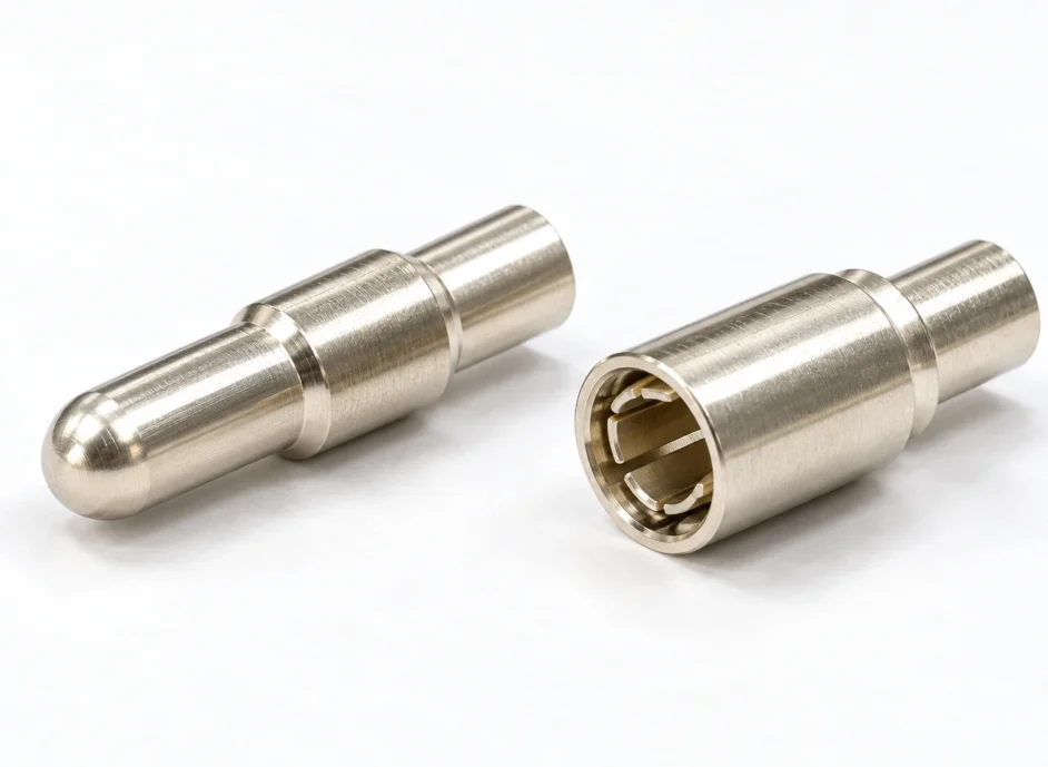
IMMERSION COOLING CONTACTS
접촉 계면부터 도금·수지·냉각유의 적합성 시험까지
IMMERSION COOLING CONTACTS
접촉력과 도금, 하우징 수지와 케이블을 실제 냉각유 조건으로 검토해 전기적 성능과 재료 변화를 함께 확인합니다.
CONTACT FORCE · PLATING · MATERIAL COMPATIBILITY · SOAK TEST
액침냉각 커넥터 접점 설계는 냉각 방식과 함께 달라지는 재료 환경에서 출발합니다. AI 서버처럼 발열 밀도가 높은 장비를 탱크에 넣으면 메모리 슬롯과 확장 카드, 전원 커넥터가 절연성 유체에 장시간 노출됩니다. 접점은 전류를 안정적으로 흘려야 하면서도, 하우징과 케이블에서 나온 성분이 냉각유의 상태를 바꾸지 않아야 합니다.
공기 냉각용 커넥터를 그대로 담가도 되는지, 하우징이나 케이블이 부풀지 않는지, 금도금이 여전히 필요한지 같은 질문은 결국 하나로 모입니다. 액침냉각 커넥터 접점, 그리고 그 주변 재료가 사용할 냉각유와 맞는가입니다. 이 글에서는 접촉 계면에서 일어나는 일부터 도금과 피막, 하우징 수지·씰·케이블, 침지 적합성 시험과 결과 해석까지 차례로 살펴봅니다.
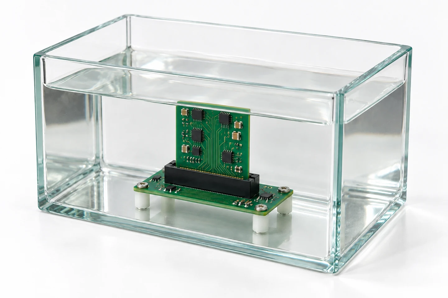
IMMERSION TANK / 냉각유 속에서 결합된 카드 엣지 커넥터
액침냉각은 절연성 유체가 장비와 직접 접촉해 열을 옮기는 방식입니다. 단상 시스템은 유체가 액체 상태를 유지하고, 2상 시스템은 비등과 응축을 이용합니다. 이 구분만으로 재료 적합성을 판단할 수는 없습니다. 같은 단상 방식이라도 유체의 조성과 첨가제, 점도, 사용 온도가 다르므로 제품명과 등급을 특정해야 합니다.
공기와 다른 환경이 생겼다고 해서 산화와 부식이 자동으로 사라지는 것은 아닙니다. 유체의 수분과 오염물, 부품에서 용출된 성분, 정비 중 공기 노출이 함께 작용합니다. 냉각 성능이 좋아져도 접점의 도금이나 절연 재료 검증을 생략할 근거가 되지는 않습니다.
하우징 수지와 래치, 씰, 케이블 피복, 라벨은 같은 유체에 계속 노출됩니다. 성분이 유체로 빠져나가거나 유체를 흡수하면 치수와 강성, 절연 특성이 달라질 수 있습니다. 고속 신호 커넥터는 주변 매질의 변화까지 고려해야 합니다.
정비에서는 탱크에서 꺼낸 부품에 남아 있는 유체가 중요합니다. 공기 중 건조 상태, 유체가 묻은 상태, 완전히 잠긴 상태를 구분해 결합력과 접촉저항을 비교합니다. 절연성 냉각유를 사용한다는 사실만으로 통전 중 분리·결합이 허용되지는 않으므로, 커넥터 사양과 장비의 정비 절차도 함께 정합니다.
맞닿은 금속면은 넓게 붙어 보여도 실제로는 표면 돌기의 작은 점들에서 금속끼리 닿습니다. 액침 환경에서는 이 접촉점 주변의 틈을 냉각유가 채울 수 있습니다. 카드가 들어오며 접점 빔을 벌리는 동안 유체도 이동하지만, 접촉력만으로 유막이 충분히 배제된다고 단정할 수는 없습니다. 전류가 흐르는 미세 접촉점이 안정적으로 유지되는지를 실제 유체 속 측정으로 확인합니다.
유막의 영향은 신호용과 전원용이라는 분류만으로 정해지지 않습니다. 접촉력과 접촉부 곡률, 표면 거칠기, 유체 점도, 결합 속도와 온도가 함께 작용합니다. 특히 하중이 작은 접점은 유체가 개입한 상태의 저레벨 접촉저항을 확인해야 합니다. 윤활유를 바른 접점의 미동 시험 결과를 서로 다른 냉각유에 그대로 적용하거나, 그 결과만으로 최소 접촉력을 정해서는 안 됩니다.
유체는 미동 마모의 양상도 바꿉니다. 온도 변화나 진동으로 접촉점이 미세하게 움직일 때, 유체가 마찰면을 적셔 산화 마모 부스러기가 쌓이는 과정을 늦출 수 있습니다. 다만 이 효과를 설계 여유로 계산하기보다는, 실제 냉각유 속에서 온도 순환과 진동을 준 뒤 저항 추이를 보는 편이 안전합니다.
고속 신호 커넥터는 유체의 유전율과 손실 특성이 주파수·온도에 따라 어떻게 달라지는지 봅니다. 공기 중에 맞춘 임피던스와 삽입 손실이 침지 후에도 유지되는지는 실제 유체와 결합 상태에서 S-파라미터와 아이 다이어그램으로 확인합니다. 정비 후에는 캐비티의 잔류 유체와 젖은 상태의 결합·분리력이 반복 결합에 주는 영향도 함께 평가합니다.
| 변화 | 접점에서 생기는 일 | 확인할 것 |
|---|---|---|
| 접촉면 사이 유막 | 접촉 초기 저항에 영향, 접촉력이 낮을수록 민감 | 유체 속 저레벨 접촉저항, 설계 접촉력 |
| 미동과 윤활 | 유체가 마찰면을 적셔 미동 마모 양상이 달라짐 | 온도 순환·진동 뒤 저항 추이 |
| 주변 매질의 유전율 | 고속 신호의 임피던스·삽입 손실 변화 | 유체 속 S-파라미터, 아이 다이어그램 |
| 유체에 섞인 오염물 | 황·할로겐·유기산이 금속 부식을 부를 수 있음 | 유체 분석, 노출 금속면 외관 |
| 정비 때 인출·재결합 | 젖은 상태의 분리·결합, 캐비티 잔류 유체 | 젖은 상태 결합·분리력과 저항 |
접점에서 생기는 일 · 확인할 것
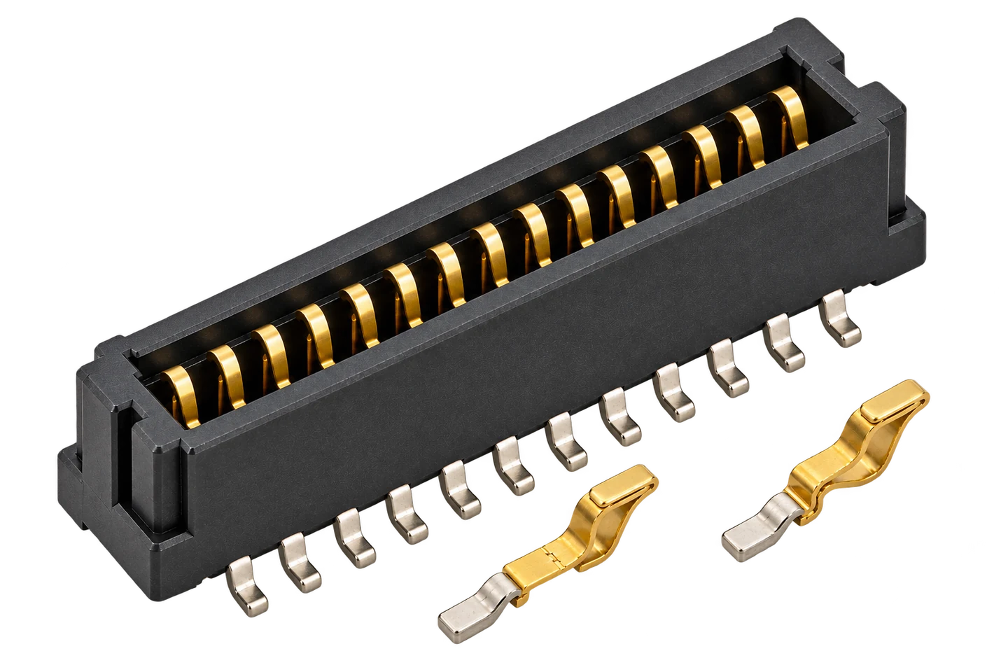
접촉점에서는 접촉력이 유막을 밀어내고, 금속끼리 닿은 미세한 점이 전류 경로가 됩니다. 확대 그림처럼 동합금 모재 위에 니켈 하지와 금 도금이 있고 카드 패드도 금으로 마감합니다. 접촉력이 낮은 신호 접점은 유체 속에서 접촉저항을 다시 확인합니다.
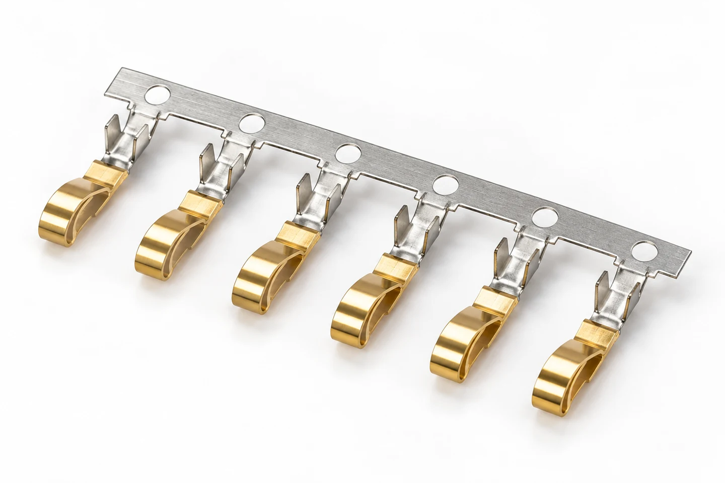
카드 엣지나 메모리 슬롯의 신호 접점은 보통 동합금 모재에 니켈 하지 도금을 올리고, 접촉부에 금 도금을 둡니다. 금은 표면 피막이 거의 생기지 않아 작은 접촉력에서도 저항이 안정적이기 때문입니다. 비용을 줄이려고 접촉부에만 금을 올리고, 납땜이나 압입되는 꼬리부는 주석 같은 다른 마감으로 나누는 부분 도금이 흔합니다.
냉각유에 잠긴다는 이유만으로 금도금 두께를 줄일 수는 없습니다. 접점은 조립과 출하, 정비 과정에서 공기에 노출되고, 침지 중에도 도금의 기공이나 절단면으로 모재가 드러날 수 있습니다. 금 두께와 니켈 하지, 표면 상태, 결합 마모를 함께 보고 건조·침지·인출 후 조건에서 성능을 비교합니다.
유체 자체보다 유체에 섞여 드는 오염물이 금속을 상하게 하는 경우도 있습니다. 케이블 피복이나 라벨, 납땜 플럭스 잔사에서 녹아 나온 황과 할로겐, 유기산은 노출된 동이나 은, 주석 표면의 부식을 부를 수 있습니다. 그래서 도금의 핀홀이나 절단면처럼 모재가 드러난 곳과 은 도금의 변색 여부를 시험 뒤에 따로 살핍니다.
공기 냉각용 커넥터에 쓰던 접점 윤활제나 표면 처리제도 냉각유에 씻겨 나갈 수 있습니다. 윤활제로 삽입력이나 미동 마모를 관리하던 설계라면, 유체 속에서 결합력과 저항을 다시 재어 보는 것이 좋습니다. 전원 접점의 은·주석 도금도 같은 이유로 실제 유체와 온도 조건에서 다시 확인합니다.
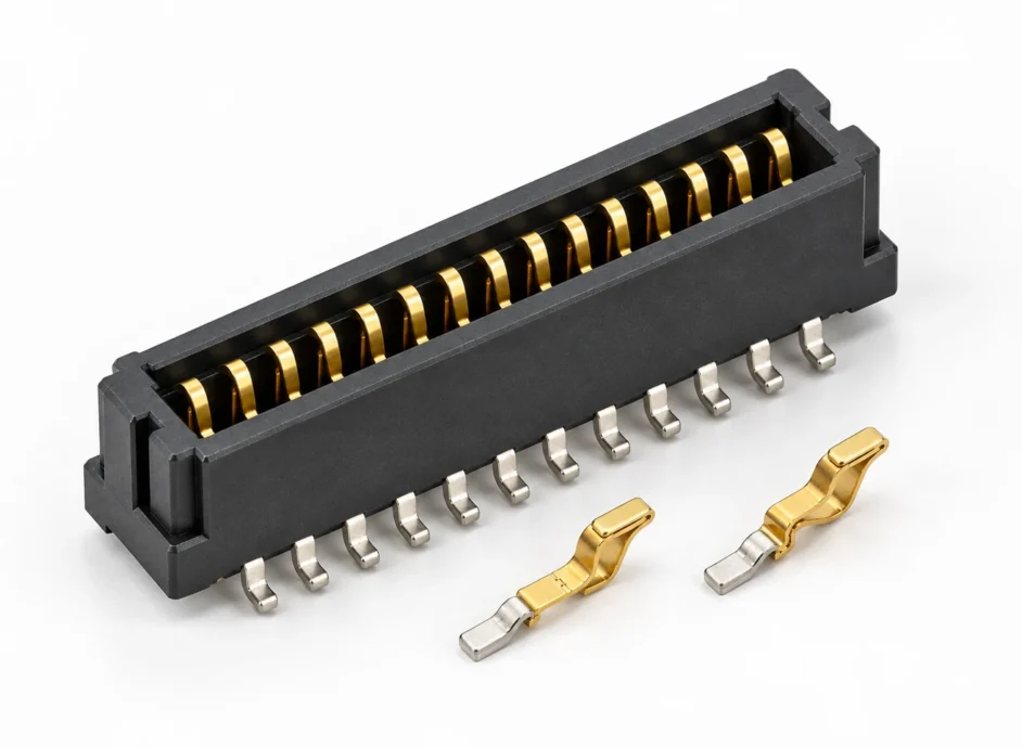
SELECTIVE PLATING / 접촉부와 꼬리부의 표면 마감을 나눈 접점 스트립
접점의 위치와 접촉력을 붙잡는 것은 하우징 수지입니다. 수지가 유체를 흡수해 부풀거나 성분이 빠져 줄어들면 접점 사이 간격과 고정 위치가 달라집니다. 래치가 굳거나 갈라질 수도 있습니다. 커넥터와 소켓, 클립에서는 팽윤에 따른 치수 변화와 래치의 경화·균열이 대표적인 위험입니다.
씰은 고무의 계열명만으로 선택하기 어렵습니다. 같은 계열이라도 배합과 가교 방식에 따라 팽윤과 경도 변화가 다릅니다. 하우징 수지도 정확한 등급과 충전재·첨가제, 성형 이력을 확인해야 합니다. 원재료 시편의 변화가 작더라도, 응력이 걸린 래치와 얇은 격벽을 가진 실제 부품에서는 유지력이나 균열을 별도로 살핍니다.
케이블 피복은 유체에 노출된 뒤의 유연성과 치수도 확인합니다. 예를 들어 PVC 피복의 가소제가 특정 냉각유로 추출되면 피복이 뻣뻣해지고 유체의 조성이 달라질 수 있습니다. 변화의 정도는 피복 배합과 유체, 온도, 노출 시간에 따라 달라집니다. 정비 때 구부리는 부위의 균열과 절연 성능을 살피고, 유체가 도체를 따라 커넥터 안쪽으로 스며드는 모세관 현상도 확인합니다.
추출된 성분은 한 부품에만 머물지 않고 유체를 통해 다른 부품으로 이동할 수 있습니다. 2상 시스템에서는 비휘발성 잔류물이 열을 전달하는 표면에 쌓이는 문제도 검토합니다. 재료별 침지 시험으로 원인을 좁힌 다음 조립체 시험으로 상호 영향을 확인합니다. 속슬렛 추출은 용출 경향을 보는 방법 중 하나이며, 그 결과만으로 작동 중 커넥터의 전기적 성능을 판정하지 않습니다.
| 재료 | 나타날 수 있는 변화 | 측정할 것 |
|---|---|---|
| 하우징·래치 수지 | 팽윤·수축에 따른 치수 변화, 래치 경화·균열 | 치수, 질량, 래치 유지력 |
| 씰·패킹 고무 | 팽윤, 경도 변화 | 부피 변화, 쇼어 경도 |
| 케이블 피복 | 가소제 용출로 경화, 유체 오염, 도체를 따라 스며듦 | 굽힘·당김, 모세관 침투, 유체 속 가소제 |
| 라벨·접착제·잉크 | 접착 약화와 탈락, 유체 변색 | 외관, 유체 색 |
| 수축 튜브·코팅 | 고온에서 분해, 부착력 저하 | 외관, 부착 상태, 유체 분석 |
나타날 수 있는 변화 · 측정할 것
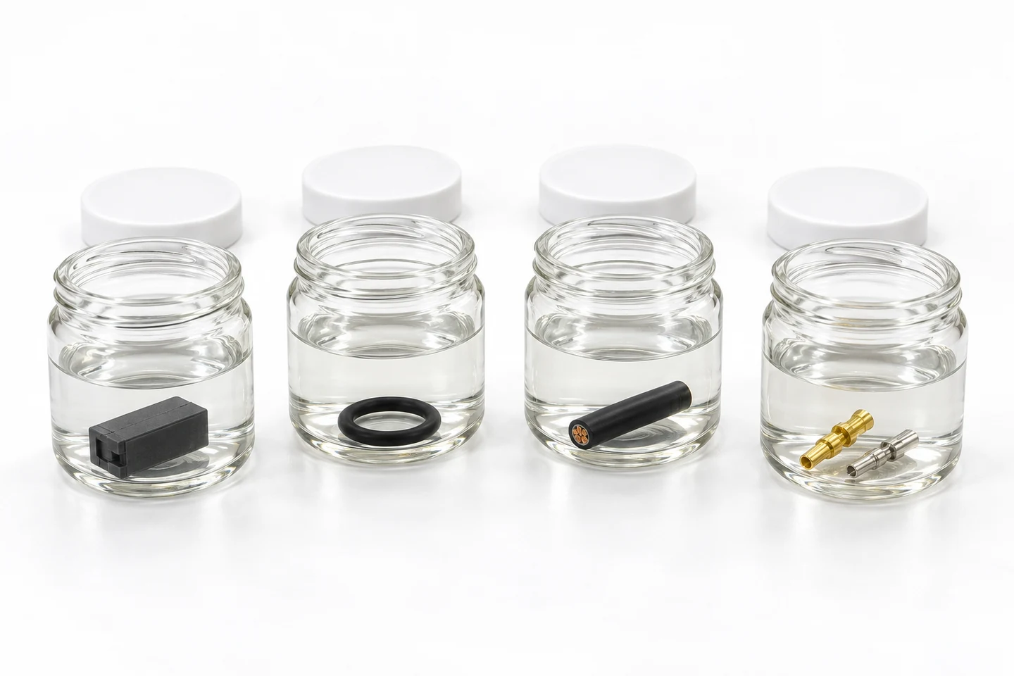
COMPATIBILITY SOAK / 수지·씰·케이블·금속 시편의 침지 평가
침지 적합성 시험은 부품과 유체를 함께 평가합니다. 시험 전에 접촉저항, 결합·분리력, 절연 성능과 치수 등 기능별 허용 범위를 정하고 초기값을 기록합니다. 전후 비교에서는 건조·젖은 상태·침지 상태를 섞지 않아야 합니다. 배액·닦음·건조 방법과 측정까지의 시간도 일정하게 맞춰야 재료 변화와 측정 조건의 영향을 구분할 수 있습니다.
시편은 보관 시편, 가열만 한 시편, 유체에 담가 가열한 시편으로 나눕니다. 유체도 받은 상태의 시료, 시편 없이 같은 조건으로 가열한 대조 시료, 시편과 함께 가열한 시료를 남깁니다. 시편 수와 유체량, 표면적 또는 질량 대비 유체 비율, 용기·뚜껑·지그 재질을 기록해 비교 조건을 맞춥니다.
재료의 열 노화 비교, 유체에 대한 침지 적합성 평가, 용출 성분을 살피는 추출 시험은 목적이 다릅니다. 속슬렛 추출의 시간이나 재료 선별용 가열 조건을 조립된 커넥터의 운전 시험 조건으로 옮겨 쓰지 않습니다. 시험 온도와 시간, 개방·밀폐 방식은 유체와 부품의 한계 및 장비 조건에 맞춰 정합니다. 단기 시험에서 변화가 작더라도 장기 수명이나 조립체의 전기적 성능이 입증된 것은 아닙니다.
인출 직후에는 외관과 유체 잔류 상태를 기록하고, 정해진 전처리 뒤 질량·부피·치수·경도를 비교합니다. 접촉저항은 낮은 전압·전류의 4단자법으로 측정합니다. 여기서 드라이 회로는 유체가 없는 건조 환경을 뜻하지 않습니다. 측정 자체가 접촉 계면의 피막이나 미세 접촉점을 변화시키지 않도록 전압과 전류를 제한하는 조건입니다.
접촉저항 측정 뒤에는 결합력, 절연저항·내전압, 실제 통전 조건의 온도 상승과 필요한 신호 특성을 각 시험에 맞는 조건으로 확인합니다. 유체는 색과 탁도·침전뿐 아니라 필요에 따라 수분, 산성 성분, 금속 이온과 용출 성분까지 분석합니다. 전기적 변화와 유체 분석 결과를 함께 보면 원인을 좁히는 데 도움이 됩니다.
재료 선별을 통과한 뒤에도 실제 조립체의 열 순환과 반복 결합, 진동, 통전 시험을 이어갑니다. 변화율만 작다고 판정하지 않고 최종 치수와 저항이 기능 허용 범위 안에 있는지 봅니다. 유체 교환이나 부품 등급 변경이 예정되어 있다면 변경 전후 조합을 같은 기준으로 비교할 수 있도록 시험 이력을 남깁니다.
꺼낸 시편은 유체를 빼고 닦기 전에 외관부터 봅니다. 그다음 질량·부피·치수·경도를 처음 값과 비교합니다. 유체도 색·탁도·침전과 녹아 나온 성분을 대조 시료와 비교합니다.
시험 결과를 읽을 때는 먼저 무엇을 시험했는지 구분해야 합니다. 수지 시편의 질량 변화가 작았다는 결과는 그 재료와 유체의 상호작용을 보여 줍니다. 그러나 접점이 장착된 하우징의 유지력이나 전기적 성능까지 설명하지는 않습니다. 재료 시편의 결과와 실제 결합된 커넥터의 결과를 연결해 판단해야 합니다.
접촉저항은 평균값과 함께 개별 접점의 변화도 봅니다. 평균이 거의 같아도 일부 접점에서만 저항이 커지거나 측정값이 불안정할 수 있기 때문입니다. 전후 비교에서는 온도와 결합 상태, 측정 위치를 맞추고, 유체가 묻은 상태와 배액 후 상태를 구분해 기록합니다. 비교 조건이 달라지면 그 차이를 재료 열화로 해석하기 어렵습니다.
시험 결과는 시험한 부품과 유체, 노출 조건의 조합에 연결해 남깁니다. 냉각유 등급이나 접점 도금, 하우징 재질이 바뀌면 이전 결과를 그대로 적용하기보다 변경된 부분이 접촉·절연·유지력에 미치는 영향을 확인합니다. 외관에 변화가 없다는 사실과 필요한 기능을 유지한다는 판단은 구분해야 합니다.
액침냉각 커넥터의 평가는 접점, 하우징, 냉각유를 함께 보는 일입니다. 실제 사용 조건에서 전기적 성능과 기계적 기능이 유지되는지 확인할 때 재료 적합성 시험의 의미가 분명해집니다.
궁금한 사항은 아래 문의 양식으로 남겨 주세요.
Please use the form below to send your enquiry.
IMMERSION COOLING CONTACTS
Review contact force, plating, housing resin and cables in the intended coolant to verify electrical performance alongside material changes.
CONTACT FORCE · PLATING · MATERIAL COMPATIBILITY · SOAK TEST
ENGLISH EDITION
An immersed connector brings metal, polymer and coolant into one design decision.
Immersion cooling changes the connector environment as well as the thermal design of high-density equipment such as AI servers. Memory slots, add-in cards and power connectors placed inside the tank are exposed to dielectric fluid for extended periods. Immersion cooling connector contacts must maintain stable conduction while the housing and cable materials must not adversely alter the coolant.
Can an air-cooled connector simply be submerged? Will housings or cables swell? Is gold plating still needed? These questions come down to one point. Do the immersion cooling connector contacts and the materials around them suit the coolant that will be used? This article starts with what happens at the contact interface. It then covers plating and coatings, housing resin, seals and cables, compatibility testing and interpretation of the results.
IMMERSION TANK / A mated card-edge connector submerged in coolant
Immersion cooling transfers heat through direct contact between equipment and a dielectric fluid. Single-phase systems retain the liquid phase; two-phase systems use boiling and condensation. This distinction alone does not establish material compatibility. Even within single-phase systems, chemistry, additives, viscosity and operating temperature differ, so the fluid product and grade must be identified.
Replacing air with fluid does not automatically eliminate oxidation or corrosion. Water content, contaminants, substances extracted from components and exposure to air during service can act together. Improved cooling does not remove the need to qualify contact plating and insulating materials.
Housing resin, latches, seals, cable jackets and labels remain exposed to the same fluid. Extraction of constituents or absorption of coolant can alter dimensions, stiffness and insulation properties. High-speed connectors also require assessment of the changed dielectric environment.
Fluid retained after lift-out matters during service. Dry-in-air, wet-in-air and fully immersed conditions are distinguished when comparing mating force and contact resistance. A dielectric coolant does not itself permit live mating or unmating; the connector rating and equipment service procedure determine that practice.
Mating metal surfaces appear broadly in contact, but current passes through small metal-to-metal asperity spots. Coolant can occupy the gaps around these spots in an immersed connector. Fluid moves as the card enters and spreads the contact beams, yet contact force alone does not establish adequate displacement of the film. Measurements in the actual fluid are needed to confirm stable conducting contact spots.
Signal or power classification alone does not determine the influence of the fluid film. Contact force and curvature, surface roughness, fluid viscosity, mating speed and temperature act together. Low-force contacts particularly require low-level contact resistance measurements with the fluid present. Fretting results from lubricated contacts cannot be transferred directly to different coolants or used alone to define a minimum contact force.
Fluid also changes how fretting proceeds. Temperature changes or vibration can move the contact point slightly. The fluid then wets the sliding surfaces and can slow the build-up of oxidised wear debris. It is safer not to count this as design margin. Apply thermal cycling and vibration in the actual coolant and watch the resistance trend.
For high-speed connectors, fluid permittivity and dielectric loss are considered at the relevant frequency and temperature. S-parameters and eye diagrams in the intended fluid and mated condition establish whether impedance and insertion loss remain acceptable after immersion. Retained fluid in cavities and wet mating and unmating forces are also assessed for repeated service cycles.
| Change | What happens at the contact | What to check |
|---|---|---|
| Fluid film between surfaces | Affects initial resistance; more sensitive at low force | Low-level contact resistance in fluid, design contact force |
| Micromotion and lubrication | Fluid wets sliding surfaces and changes fretting behaviour | Resistance trend after thermal cycling and vibration |
| Permittivity of the medium | Impedance and insertion loss of high-speed signals shift | S-parameters and eye diagrams in fluid |
| Contaminants in the fluid | Sulfur, halides and organic acids can corrode metals | Fluid analysis, appearance of exposed metal |
| Lift-out and re-mating | Unmating and mating while wet, fluid left in cavities | Wet mating and unmating force and resistance |
What happens at the contact · What to check
At the contact point, contact force pushes the fluid film aside, and tiny metal-to-metal spots carry the current. As the magnified view shows, nickel underplate and gold plating sit on the copper-alloy base, and the card pad is also gold-finished. For low-force signal contacts, contact resistance is checked again in the fluid.
Signal contacts in card-edge connectors and memory slots usually have a copper-alloy base with a nickel underplate. Gold plating is applied at the contact zone. Gold forms almost no surface film, so its resistance stays stable even at low contact force. Selective plating is common to control cost. Gold goes only on the contact zone, and tails that are soldered or press-fitted get another finish such as tin.
Immersion alone does not justify reducing gold thickness. Contacts are exposed to air during assembly, shipping and service, and pores or sheared edges can expose the base metal even while submerged. Gold thickness, nickel underplate, surface condition and mating wear are reviewed together across dry, immersed and post-lift-out conditions.
Sometimes contaminants carried into the fluid, rather than the fluid itself, attack the metal. Cable jackets, labels and solder flux residue can release sulfur, halides and organic acids. These can promote corrosion of exposed copper, silver or tin. After testing, exposed base metal such as plating pinholes and sheared edges is therefore examined separately. Silver plating is checked for tarnish.
Contact lubricants or surface treatments used on air-cooled connectors can also be washed away by the coolant. Some designs rely on a lubricant to control insertion force or fretting. Their mating force and resistance should be measured again in the fluid. For the same reason, silver or tin plating on power contacts is re-checked under the actual fluid and temperature conditions.
SELECTIVE PLATING / Contact strip with distinct contact-zone and tail finishes
The housing resin holds the contacts in position and maintains their contact force. If the resin absorbs fluid and swells, or loses constituents and shrinks, contact spacing and retention positions change. Latches can harden or crack. For connectors, sockets and clips, dimensional change from swelling and hardening or cracking of latches are the typical risks.
The elastomer family name alone is insufficient for seal selection. Formulation and cure system can change swelling and hardness behaviour within the same family. Housing resins likewise require the exact grade, fillers, additives and processing history. Even if a material coupon shows little change, stressed latches and thin partitions in the actual component need separate retention and crack assessments.
Cable jackets also need flexibility and dimensional checks after fluid exposure. For example, extraction of plasticizer from a PVC jacket by a particular coolant can stiffen the jacket and alter the fluid composition. The extent depends on jacket formulation, fluid, temperature and exposure time. Check cracking at service flex points and insulation performance, together with capillary transport of fluid along conductors into the connector.
Extracted constituents can travel through the fluid from one component to another. Two-phase systems also require attention to non-volatile residues on heat-transfer surfaces. Individual material soaks help isolate causes; assembly-level tests then assess interactions. Soxhlet extraction is one way to examine extractable constituents, but its result alone does not qualify the electrical performance of an operating connector.
| Material | Possible change | What to measure |
|---|---|---|
| Housing and latch resin | Dimensional change from swelling or shrinkage, latch hardening or cracking | Dimensions, mass, latch retention |
| Seal and gasket elastomers | Swelling, change in hardness | Volume change, Shore hardness |
| Cable jackets | Stiffening from plasticizer loss, fluid contamination, wicking along conductors | Flex and pull, capillarity, plasticizer in fluid |
| Labels, adhesives and inks | Weakened adhesion and detachment, fluid discolouration | Appearance, fluid colour |
| Heat-shrink tubing and coatings | Breakdown at high temperature, loss of adhesion | Appearance, adhesion, fluid analysis |
Possible change · What to measure
COMPATIBILITY SOAK / Polymer, seal, cable and metal specimens for immersion evaluation
An immersion compatibility programme evaluates the component and fluid together. Functional acceptance limits for contact resistance, mating forces, insulation and dimensions are defined before recording baseline values. Dry, wet and immersed measurement states must not be mixed in before-and-after comparisons. Drainage, wiping, drying and the interval before measurement are controlled to separate material change from measurement-condition effects.
Specimens include an unexposed control, a heated-only reference and a heated-and-immersed group. Fluid samples include the as-received fluid, a blank heated under the same conditions without specimens and fluid heated with specimens. Record specimen count, fluid quantity, the surface-area or mass-to-fluid ratio, and the materials of containers, lids and fixtures so that comparisons are reproducible.
Thermal ageing comparisons, fluid compatibility soaks and extraction tests address different questions. A Soxhlet extraction duration or a material-screening heat exposure should not be reused as an operating test for an assembled connector. Select temperature, duration and open or closed arrangements to suit the fluid, component and equipment limits. Small changes in a short test do not establish service life or the electrical performance of the assembly.
Record appearance and retained fluid immediately after lift-out, then compare mass, volume, dimensions and hardness after the specified conditioning. Measure contact resistance by a four-wire method at low voltage and current. In this context, a dry circuit does not mean a physically dry environment. It limits voltage and current so that the measurement does not alter surface films or microscopic contact spots.
Follow resistance measurements with mating force, insulation resistance and dielectric withstand, temperature rise under the intended load, and relevant signal tests under their respective conditions. Fluid checks may extend beyond colour, haze and sediment to water content, acidic species, metal ions and extractable constituents. Comparing electrical changes with fluid analysis helps narrow down the cause.
After material screening, the actual assembly still requires the relevant thermal cycling, repeated mating, vibration and powered tests. A small percentage change alone is insufficient; final dimensions and resistance must remain within functional limits. Retain test histories so that a replacement coolant or material-grade change can be compared against the same acceptance criteria.
After removal and draining, appearance is checked before the coupons are wiped. Mass, volume, dimensions and hardness are then compared with the starting values. The fluid is also compared with the control for colour, haze, sediment and extracted substances.
Start by identifying what was tested. A small mass change in a polymer coupon describes the interaction between that material and the fluid. It does not establish contact retention or electrical performance in an assembled housing. Material results therefore need to be considered alongside tests on the actual mated connector.
Review individual contacts as well as the average resistance. An unchanged average can conceal a rise or unstable readings at a small number of contacts. Before-and-after measurements should use consistent temperature, mating state and measurement locations, with wet and drained conditions recorded separately. Otherwise, a measurement-condition difference may be mistaken for material degradation.
Keep each result linked to the tested component, fluid and exposure conditions. A change in coolant grade, contact finish or housing material calls for review of its effects on contact performance, insulation and retention before earlier results are reused. An unchanged appearance and continued functional performance are separate findings.
Evaluating an immersion-cooled connector means considering its contacts, housing and coolant together. Material compatibility results become meaningful when electrical and mechanical performance are verified under the intended operating conditions.

액침냉각 커넥터의 적합성은 금속 접점만으로 결정되지 않습니다. 실제 냉각유에서 도금과 접촉력이 전기적 성능을 유지하는지, 하우징·씰·케이블의 변화가 조립과 절연에 영향을 주는지, 용출 성분이 유체를 바꾸는지를 함께 평가합니다. 재료 선별 결과를 조립체의 전기·기계 시험과 연결해 실제 사용 조건에서의 적합성을 판단합니다.
01 / 유체 특정 — 단상·2상 구분에 더해 제품명, 등급, 조성 정보, 운전 온도와 교환 계획을 확보합니다.
02 / 접촉 계면 — 접촉력과 곡률, 표면 상태, 유체 점도 및 결합 속도를 함께 검토합니다.
03 / 도금 구성 — 접촉부·꼬리부·절단면을 구분하고 니켈 하지, 금 또는 기타 마감, 기공과 마모를 확인합니다.
04 / 수지·씰·케이블 — 계열명이 아닌 실제 등급과 배합을 기준으로 치수·경도·유지력·절연 변화를 봅니다.
05 / 시험 대조군 — 열만 가한 시편과 유체만 가열한 시료를 두고 시편 대 유체 비율과 용기 재질을 기록합니다.
06 / 측정 상태 — 건조·젖은 상태·침지 상태와 배액·건조 시간을 구분해 전후 데이터를 비교합니다.
07 / 조립체 검증 — 재료 침지 후에도 반복 결합, 열 순환, 통전 온도 상승과 필요한 고속 신호 시험을 연결합니다.
외형과 정격이 같다는 이유로 적용을 확정하기 어렵습니다. 사용할 냉각유의 정확한 제품·등급과 온도에서 하우징, 도금, 씰과 케이블을 검토하고 결합력·접촉저항·절연 성능을 확인한 뒤 판단합니다.
단상·2상은 열을 옮기는 방식의 구분입니다. 유체 조성과 온도, 비등·응축 조건이 다르면 추출과 팽윤, 잔류물의 거동도 달라집니다. 다른 유체나 운전 방식으로 바뀌면 해당 조합을 별도로 검토합니다.
침지만으로 금도금의 두께나 범위를 줄일 근거는 생기지 않습니다. 접촉력, 기공과 마모, 상대 접점의 마감, 정비 중 공기 노출을 함께 고려해 기존 사양과 변경 사양을 비교합니다.
재질명 외에도 등급, 충전재와 첨가제, 성형 조건이 필요합니다. 같은 계열의 수지라도 결과가 다를 수 있으며, 평판 시편과 응력이 걸린 실제 래치·격벽의 결과도 같다고 볼 수 없습니다.
단기 시험은 재료와 유체의 조합을 비교하고 변화의 원인을 좁히는 데 쓰입니다. 장기 수명이나 제품 인증을 뜻하지 않습니다. 실제 온도와 통전 조건, 열 순환, 정비와 반복 결합을 반영해 조립체의 기능이 유지되는지 확인합니다.
전후 측정의 온도와 결합 상태, 시험 전압·전류, 건조·젖음·침지 조건을 맞춥니다. 4단자 측정으로 리드선 영향을 줄이고 배액·닦음·건조 절차를 기록합니다. 평균값과 함께 개별 접점의 변화와 불안정 여부도 봅니다.
접촉저항은 필요한 항목 중 하나입니다. 주변 유전체가 달라지므로 목표 주파수와 온도에서 임피던스, 삽입·반사 손실, 누화와 아이 다이어그램 등 인터페이스에 맞는 지표를 평가합니다.
시험한 부품과 유체의 조합을 먼저 확인해야 합니다. 형상이 비슷해도 도금, 수지 등급, 접촉력과 운전 조건이 다르면 결과가 달라질 수 있습니다. 변경된 항목을 확인하고 필요한 기능을 같은 기준으로 비교합니다.
접촉 영역과 꼬리부, 절단면의 마감이 다른 경우 각 표면의 유체 노출과 실제 결합 위치, 기공·마모에 따른 변화를 구분해 봅니다.
탱크 인출 후의 배액과 캐비티 잔류 유체가 결합력·유지력·접촉저항에 주는 영향을 정비 횟수와 함께 봅니다.
개별 재료의 침지 결과를 하우징, 래치, 케이블을 포함한 조립체의 전기·기계 시험과 연결합니다.
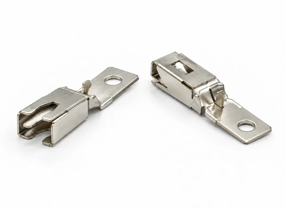
서버 PDU 콘센트 접점 — 전원 접점의 결합과 접촉 특성
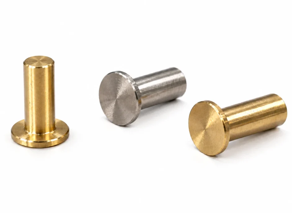
리벳 접점 조립품 — 스프링 접점의 접촉력과 품질관리
액침냉각커넥터 접점카드 엣지접촉력접촉저항부분 도금하우징 수지유체 적합성침지 시험용출 성분신호 무결성
Immersion compatibility depends on more than the metal contacts. Evaluate electrical performance of the finish and contact system in the actual coolant, changes in housing, seals and cables, and the effect of extracted constituents on the fluid. Connect material screening to electrical and mechanical tests on the assembly under the intended operating conditions.
01 / Identify the fluid — Obtain the product and grade, chemistry information, operating temperature and replacement plan as well as the single-phase or two-phase classification.
02 / Contact interface — Review force and curvature, surface condition, fluid viscosity and mating speed together.
03 / Plating system — Distinguish contact zones, tails and sheared edges; assess underplate, finish, porosity and wear.
04 / Polymers and cables — Evaluate dimensional, hardness, retention and insulation changes for the actual grades and formulations.
05 / Test controls — Include heated-only specimens and fluid blanks; record specimen-to-fluid ratio and vessel materials.
06 / Measurement state — Separate dry, wet and immersed conditions and control drainage and drying intervals.
07 / Assembly validation — Follow material screening with repeated mating, thermal cycling, powered temperature-rise and relevant high-speed signal tests.
Matching dimensions and ratings are insufficient to confirm suitability. Review the housing, plating, seals and cables in the exact intended fluid grade and temperature, then verify mating forces, contact resistance and insulation performance.
The phase classification describes heat transfer. Different fluid chemistry, temperature and boiling or condensation conditions change extraction, swelling and residue behaviour. A different fluid or operating mode requires review of that specific combination.
Immersion alone does not justify reducing gold thickness or coverage. Consider contact force, porosity, wear, the mating finish and air exposure during service, and compare the existing specification with the proposed change.
The grade, fillers, additives and processing conditions are also needed. Grades within one polymer family can differ, and flat coupons do not reproduce the stresses in an actual latch or thin partition.
A short soak compares material and fluid combinations and helps identify causes of change. It does not establish service life or product certification. Verify assembly functions with the relevant temperature, electrical load, thermal cycling, service and repeated-mating conditions.
Match temperature, mating state, test voltage and current, and dry, wet or immersed conditions. Use a four-wire measurement to reduce lead resistance and document drainage, wiping and drying. Review individual contact changes and instability as well as the average.
It is only one required measurement. The changed dielectric environment also calls for interface-appropriate impedance, insertion and return loss, crosstalk and eye-diagram evaluation at the target frequency and temperature.
First identify the component and fluid combination that was tested. Similar geometry does not ensure equivalent results when the finish, polymer grade, contact force or operating conditions differ. Review the changes and compare the relevant functions against consistent acceptance criteria.
Distinguish the contact zone, tail and cut edges when their finishes differ. Review fluid exposure, actual mating location, porosity and wear for each surface.
Evaluate how drainage and fluid left in cavities after lift-out affect mating force, retention and contact resistance across service cycles.
Connect individual material-soak results to electrical and mechanical tests of assemblies containing the housing, latches and cables.
Server PDU Receptacle Contacts — Mating and contact behaviour in power connections
Riveted Contact Assemblies — Contact force and quality control for spring contacts
Immersion coolingConnector contactsCard edgeContact forceContact resistanceSelective platingHousing resinFluid compatibilitySoak testingExtractablesSignal integrity
연결 준비 중입니다. 현재 전화 연결을 이용하실 수 있습니다.