CONNECTOR SYSTEM / 밀봉 하우징과 단자 결합 구조

AUTOMOTIVE CONTACT RELIABILITY

자동차 전기접점
신뢰성을 설계하다

진동·열 이력·프레팅·접촉저항을 연결하는 검증 기준

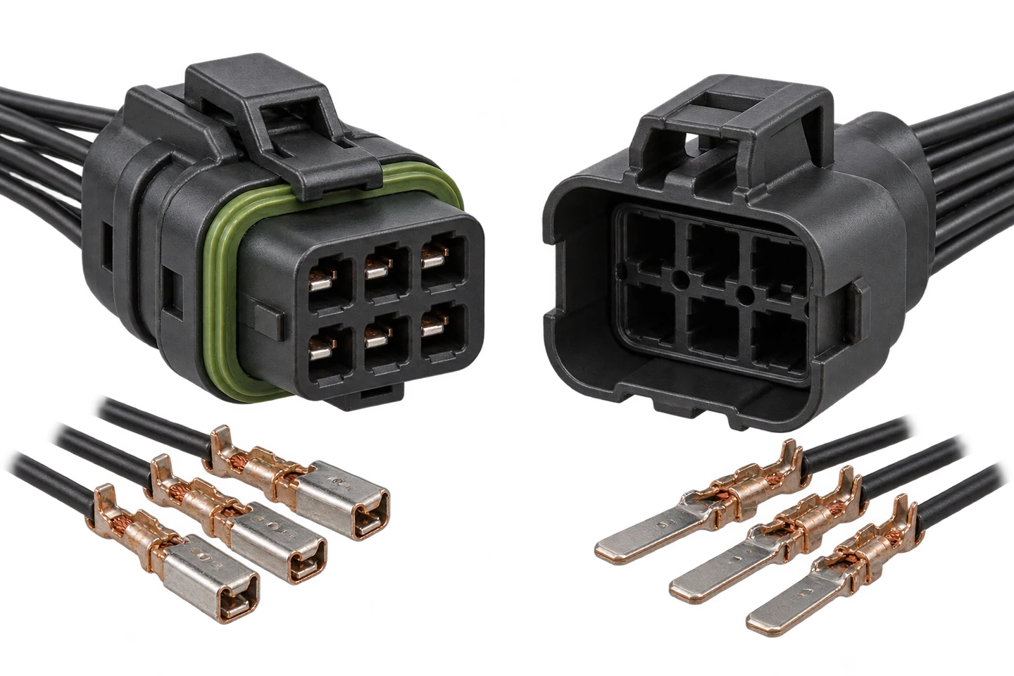
CONNECTOR SYSTEM / 밀봉 하우징과 단자 결합 구조

Contact.
Cycle.
Trust.

AUTOMOTIVE CONTACT RELIABILITY

CONNECTOR SYSTEM / 밀봉 하우징과 단자 결합 구조

Reliable Connections.

작은 접촉면의 안정성을 하네스·환경·조립 조건까지 연결합니다.

VIBRATION · THERMAL · FRETTING · TEST

Overview.

Stable contact.
Through every cycle.

자동차 전기 연결의 문제는 정지 상태에서 드러나지 않을 수 있습니다. 짧은 단속, 고온 이후의 접촉력 감소, 미세 운동에 의한 표면 변화가 정상과 고장 사이를 오가며 회로 기능을 흔들 수 있습니다.

이 글은 단자 형상과 소재에서 하우징·실·크림프·하네스 지지까지 연결하고, 실제 설계 및 시험 계획에 필요한 판단 기준을 정리합니다. 전압 등급·장착 위치·측정 조건을 분명히 하여 초기 저항부터 복합 환경 후 상태까지 검증하는 기준을 제시합니다.

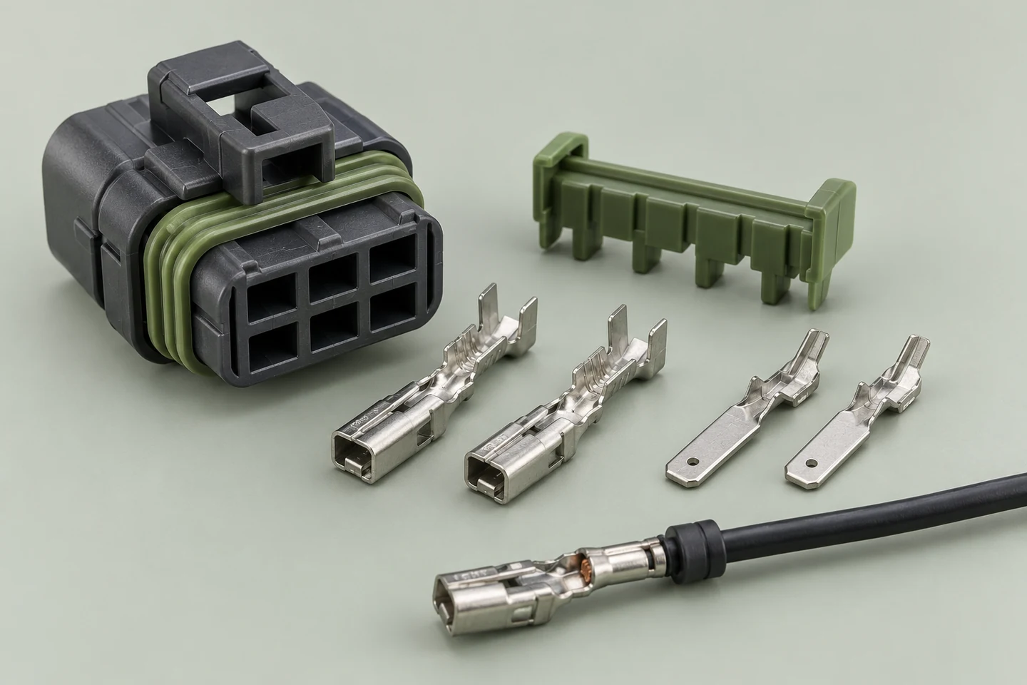
COMPONENTS / 하우징·잠금·암단자·수단자

COMPONENTS / 하우징·잠금·암단자·수단자

System.

실제 장착 조건을 시험과 설계의 공통 기준으로 만듭니다.

01 / SYSTEM BOUNDARY

접점 신뢰성은 단자부터 하네스 지지까지의 문제입니다

자동차의 진동·온도·습기는 접촉면에 서로 다른 경로로 전달됩니다.

자동차 커넥터의 전기 연결은 단자 접촉면, 크림프와 전선, 하우징과 잠금, 실과 배선 지지가 함께 유지합니다. 접촉면만 확대해 관찰하면 하우징 유격이나 케이블 움직임이 만든 원인을 놓칠 수 있습니다. 검토 범위는 센서·전원·통신 등 회로 기능과 실제 장착 위치에서 시작합니다.

엔진 근처와 실내, 도어와 차체 하부는 온도 이력과 진동 입력, 물질 노출이 다릅니다. 같은 단자를 사용하더라도 하네스 길이와 지지점, 장착 방향이 달라지면 접촉면 상대 운동이 달라질 수 있습니다. 부품 번호와 설치 구성을 하나의 시험 정의로 묶습니다.

이 글은 분리 가능한 자동차 전기 접속의 접촉 안정성을 다룹니다. 저전압 커넥터 기준을 고전압 구동계에 그대로 확대하지 않으며, 고속 통신의 신호 무결성과 고전압 절연 요구는 해당 시스템의 별도 검증을 연결해야 합니다.

연결 경계

단자·크림프·전선·하우징·실을 연결합니다.

장착 환경

온도·진동·배선 지지의 실제 조건을 기록합니다.

회로 기능

신호·전력·전압 등급에 맞는 판정을 정합니다.

접점 신뢰성은 단자부터 하네스 지지까지의 문제입니다 — 검토 항목

검토 항목영향·조건설계·검증 연결
전기 경로접촉면·크림프·전선측정 구간과 기능 정의
기계 경로하우징·잠금·하네스상대 운동과 유지력
환경 경로실·통기·온도·노출장착 위치 기반 시험

전기 경로

영향·조건
접촉면·크림프·전선

설계·검증 연결
측정 구간과 기능 정의

기계 경로

영향·조건
하우징·잠금·하네스

설계·검증 연결
상대 운동과 유지력

환경 경로

영향·조건
실·통기·온도·노출

설계·검증 연결
장착 위치 기반 시험

02 / ELECTRICAL FAILURE

평균 저항과 순간 단속은 다른 문제를 보여줍니다

측정기의 시간 분해능이 기능 실패를 볼 수 있는지를 먼저 확인합니다.

정지 상태의 저항이 낮아도 진동 중 매우 짧은 단속이나 저항 상승이 발생할 수 있습니다. 저항 측정의 평균화와 데이터 저장 간격이 사건보다 길면 문제가 사라진 것처럼 보일 수 있으므로, 회로가 허용하는 중단 시간과 검출 조건을 시험 전에 정합니다.

전압 강하에는 단자 접촉뿐 아니라 크림프와 전선의 저항이 포함될 수 있습니다. 전류 인가점과 전압 검출점을 구분하는 4선 방식도 측정 구간을 잘못 잡으면 원인을 분리하지 못합니다. 접촉면 비교와 전체 연결 성능 평가를 서로 다른 채널이나 시험으로 정의합니다.

시험 중 사건은 가진축·주파수·온도·통전 상태와 동기화해 남깁니다. 한 번 커넥터를 다시 끼워 정상값이 나왔다면 복구가 아니라 상태 변화일 수 있으므로, 분리·재결합 전에 원래 상태의 데이터를 보존합니다.

정적 값

정의된 구간의 기준 저항을 측정합니다.

동적 사건

시간 분해능·문턱값·지속시간을 지정합니다.

상태 보존

재결합 전에 파형과 설치 상태를 기록합니다.

측정기의 시간 분해능이 기능 실패를 볼 수 있는지를 먼저 확인합니다.

검출 회로를 함께 검증합니다

발생 가능한 사건보다 느린 계측은 이상을 놓칠 수 있습니다. 알려진 시험 신호로 검출 지연과 저장 방식을 확인하고, 필터와 평균화 설정을 보고서에 남깁니다.

평균 저항과 순간 단속은 다른 문제를 보여줍니다 — 검토 항목

검토 항목영향·조건설계·검증 연결
접촉저항전류·전압 검출 위치계면과 크림프 분리
순간 단속문턱·샘플링·대역폭회로 기능과 대응
사건 이력온도·가진·통전원인 재현과 동기 분석

접촉저항

영향·조건
전류·전압 검출 위치

설계·검증 연결
계면과 크림프 분리

순간 단속

영향·조건
문턱·샘플링·대역폭

설계·검증 연결
회로 기능과 대응

사건 이력

영향·조건
온도·가진·통전

설계·검증 연결
원인 재현과 동기 분석

Interface.

표면 변화와 기계적 움직임을 하나의 원인 사슬로 봅니다.

03 / FRETTING MECHANISM

작은 반복 운동이 접촉면을 지속적으로 바꿉니다

프레팅은 진동 크기만이 아니라 접촉면의 실제 상대 변위로 설명합니다.

프레팅은 접촉한 표면 사이의 작은 반복 운동으로 마모와 표면 변화가 누적되는 현상입니다. 주석계 접점에서는 마모 잔해와 산화가 전도 경로를 불안정하게 만들 수 있습니다. 귀금속 표면도 마모되어 하부층이 노출되면 초기 상태와 다른 계면으로 작동할 수 있습니다.

시험대의 이동량과 접촉점의 미끄럼량은 같지 않습니다. 하우징과 단자의 탄성 변형, 마찰과 구속이 운동을 나누어 흡수하므로, 가능한 경우 단자 부근의 상대 운동을 확인합니다. 실제 계면의 이동을 관찰할 수 있는 계측 위치와 해상도를 정합니다.

마모 자국이 보인다는 사실만으로 전기 실패를 확정하지는 않습니다. 저항 사건, 잔해 분포, 도금 노출 위치와 접촉력 변화를 함께 연결하면 운동 억제·표면 변경·하네스 지지 중 어떤 조치가 원인에 맞는지 판단할 수 있습니다.

상대 운동

하우징과 접촉점의 움직임을 구분합니다.

표면 변화

마모·산화·하부층 노출을 확인합니다.

고장 연결

저항 사건과 마모 위치를 함께 해석합니다.

운동이 멈춘 뒤의 저항

진동이 멈추면 접촉점이 안정되어 저항이 다시 낮아질 수 있습니다. 시험 종료 후 값과 시험 중 파형을 서로 다른 관찰로 보관해야 간헐 현상을 놓치지 않습니다.

작은 반복 운동이 접촉면을 지속적으로 바꿉니다 — 검토 항목

검토 항목영향·조건설계·검증 연결
운동 입력진동·열팽창·배선 반력계면 변위 확인
마모 잔해생성·이동·축적표면 관찰과 성분 분석
도금 노출주석·귀금속·하부층최종 접촉 상태
전기 변화일시 상승·단속·회복파형과 손상 대응

운동 입력

영향·조건
진동·열팽창·배선 반력

설계·검증 연결
계면 변위 확인

마모 잔해

영향·조건
생성·이동·축적

설계·검증 연결
표면 관찰과 성분 분석

도금 노출

영향·조건
주석·귀금속·하부층

설계·검증 연결
최종 접촉 상태

전기 변화

영향·조건
일시 상승·단속·회복

설계·검증 연결
파형과 손상 대응

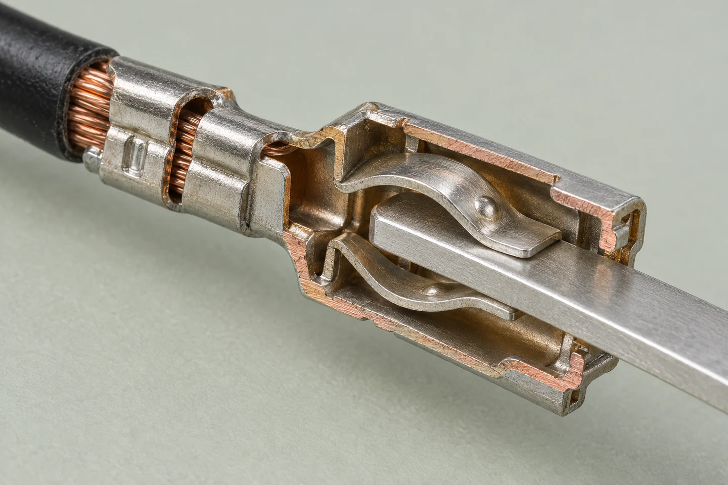
CONTACT INTERFACE / 스프링 빔과 블레이드의 접촉 구조

CONTACT INTERFACE / 스프링 빔과 블레이드의 접촉 구조

04 / SPRING CONTACT DESIGN

접촉력은 형상·조질·작동 변위의 결과입니다

힘을 키우는 선택은 삽입력·마모·응력 여유와 함께 검토합니다.

암단자의 빔은 수단자가 들어오며 변형되어 접촉력을 만듭니다. 빔 길이와 두께, 굽힘부 반경, 재료 상태와 실제 삽입 치수가 함께 힘–변위 관계를 결정합니다. 도면의 공칭 간극만으로 힘을 추정하기보다 공차 조합의 최소·최대 상태를 검토합니다.

접촉력을 높이면 일부 조건에서 전기적 안정성과 운동 억제에 도움이 되지만, 삽입 하중과 접촉면 마모, 빔 응력이 커질 수 있습니다. 조립 시 과변위나 비스듬한 삽입으로 발생한 영구 변형은 정상 작동 중 변위와 구분하여 평가합니다.

접촉 스프링과 위치 유지 구조의 역할을 분리하면 배선 또는 하우징 운동을 접촉점 밖에서 흡수하는 설계가 가능합니다. TE의 별도 위치 스프링 사례처럼 운동 경로를 조절하는 접근이 있으나, 다른 단자 형상으로 성능을 그대로 옮기려면 실물 검증이 필요합니다.

힘을 키우는 선택은 삽입력·마모·응력 여유와 함께 검토합니다.

접촉력은 형상·조질·작동 변위의 결과입니다 — 검토 항목

검토 항목영향·조건설계·검증 연결
빔 형상길이·두께·곡률힘–변위·응력
상대 단자두께·위치·삽입 길이공차 조합 평가
조립 조건각도·과변위·속도손상과 삽입력
위치 유지스프링·잠금·지지계면 상대 운동

빔 형상

영향·조건
길이·두께·곡률

설계·검증 연결
힘–변위·응력

상대 단자

영향·조건
두께·위치·삽입 길이

설계·검증 연결
공차 조합 평가

조립 조건

영향·조건
각도·과변위·속도

설계·검증 연결
손상과 삽입력

위치 유지

영향·조건
스프링·잠금·지지

설계·검증 연결
계면 상대 운동

3D · 자동차 단자의 압착·접촉 구조

STRUCTURE & INTERFACE
ID SOLUTECH / 01
인터랙티브 3D를 준비하고 있습니다.
압착·결합

압착 높이·폭·단면 상태를 규정 공구와 실제 도체로 확인합니다.

드래그·방향키: 회전 / + −: 확대·축소 / Home: 초기화자동차 단자의 압착·접촉 구조

정지 상태의 정상값이
주행 중 안정성을
보증하지는 않습니다.

Thermal.

열 이력과 접촉력 유지의 관계를 검증합니다.

05 / THERMAL RELAXATION

고온 유지 후 남아 있는 힘을 확인합니다

초기 경도와 강도만으로 장기 접촉력 유지를 설명할 수 없습니다.

응력 이완은 구속된 스프링이 시간과 온도의 영향을 받으며 힘을 잃는 현상입니다. 구리합금의 종류뿐 아니라 조질·초기 응력·방향과 제조 열 이력이 중요하므로, 합금명 하나로 잔류 접촉력을 예측하지 않습니다. 실제 굽힘과 성형 조건을 반영한 자료를 사용합니다.

재료 데이터의 일정 온도 노출과 차량의 온도 변화는 같은 이력이 아닙니다. 주위 온도에 통전 발열이 더해지고, 냉각 상태와 부하 주기가 달라질 수 있습니다. 사용 온도 범위를 소재 표의 최고 온도와만 비교하지 말고 시간 이력과 설치 상태를 함께 정의합니다.

열 노출 전후에 접촉력과 영구 변형, 삽입·분리력 및 저항을 함께 확인합니다. 고온에서 측정한 값과 상온 복귀 후 값을 혼합하면 가역적인 열 변화와 잔류 열화를 구분하기 어려우므로 측정 상태를 보고서에 명시합니다.

소재 상태

합금·조질·방향·열 이력을 확인합니다.

온도 이력

주위 온도와 통전 발열을 함께 봅니다.

잔류 기능

열 노출 후 힘·변형·저항을 평가합니다.

단품 자료와 조립체 자료

평탄한 재료 시편의 응력 이완 자료는 소재 후보 선별에 유용합니다. 실제 단자는 성형·도금·삽입 이력이 있으므로 조립체의 힘 유지 시험으로 최종 판단을 보완합니다.

고온 유지 후 남아 있는 힘을 확인합니다 — 검토 항목

검토 항목영향·조건설계·검증 연결
초기 응력성형·삽입 변위재료 시험과 대응
노출 조건온도·시간·통전실제 열 이력
측정 상태고온·상온 복귀가역·잔류 변화 분리
종료 기준최소 힘·저항·손상기능 요구 연결

초기 응력

영향·조건
성형·삽입 변위

설계·검증 연결
재료 시험과 대응

노출 조건

영향·조건
온도·시간·통전

설계·검증 연결
실제 열 이력

측정 상태

영향·조건
고온·상온 복귀

설계·검증 연결
가역·잔류 변화 분리

종료 기준

영향·조건
최소 힘·저항·손상

설계·검증 연결
기능 요구 연결

06 / PLATING AND LUBRICATION

도금과 윤활은 계면 조합으로 승인합니다

도금명이나 도포 여부만으로 프레팅 대책이 완성되지는 않습니다.

주석·은·금 등 표면 선택은 전류, 신호 수준, 삽입 횟수와 환경에 맞추어야 합니다. 동일 표면명에도 두께·경도·하부층·기공·가공 후 노출부가 다를 수 있습니다. 상대 단자까지 포함한 도금 조합과 실제 접촉 위치를 도면에 연결합니다.

윤활은 마찰과 마모, 산화 및 잔해 이동을 바꿀 수 있습니다. Swingler의 실험은 정해진 접촉 조건에서 윤활 효과를 관찰했지만, 이를 모든 그리스와 단자에 동일하게 적용할 수는 없습니다. 재료 호환성·도포량·이동·노화와 밀봉재 영향을 함께 검증합니다.

도금 또는 윤활 변경이 삽입력을 낮췄더라도 접촉 안정성의 전체 개선을 의미하지는 않습니다. 조립력·내구·환경 후 저항을 같이 비교하고, 공정에서 실제로 접촉부에 남는 상태가 승인 시편과 일치하는지 확인합니다.

도금 조합

상대면·하부층·접촉 위치를 지정합니다.

윤활 조건

종류·도포량·노화·호환성을 확인합니다.

공정 재현

승인 시편과 양산 잔류 상태를 비교합니다.

도포 공정의 균일성

윤활 효과는 제품명만이 아니라 접촉부에 실제 남는 양과 분포에 달려 있습니다. 도포 장비·취급·보관과 삽입 후 이동까지 포함하여 승인 상태를 재현합니다.

도금과 윤활은 계면 조합으로 승인합니다 — 검토 항목

검토 항목영향·조건설계·검증 연결
표면층재료·두께·경도마모와 전기 기능
하부층확산·부식·노출손상 후 상태
윤활제점도·호환성·이동온도·환경 후 비교
공정 상태세정·도포·포장실제 접촉부 재현

표면층

영향·조건
재료·두께·경도

설계·검증 연결
마모와 전기 기능

하부층

영향·조건
확산·부식·노출

설계·검증 연결
손상 후 상태

윤활제

영향·조건
점도·호환성·이동

설계·검증 연결
온도·환경 후 비교

공정 상태

영향·조건
세정·도포·포장

설계·검증 연결
실제 접촉부 재현

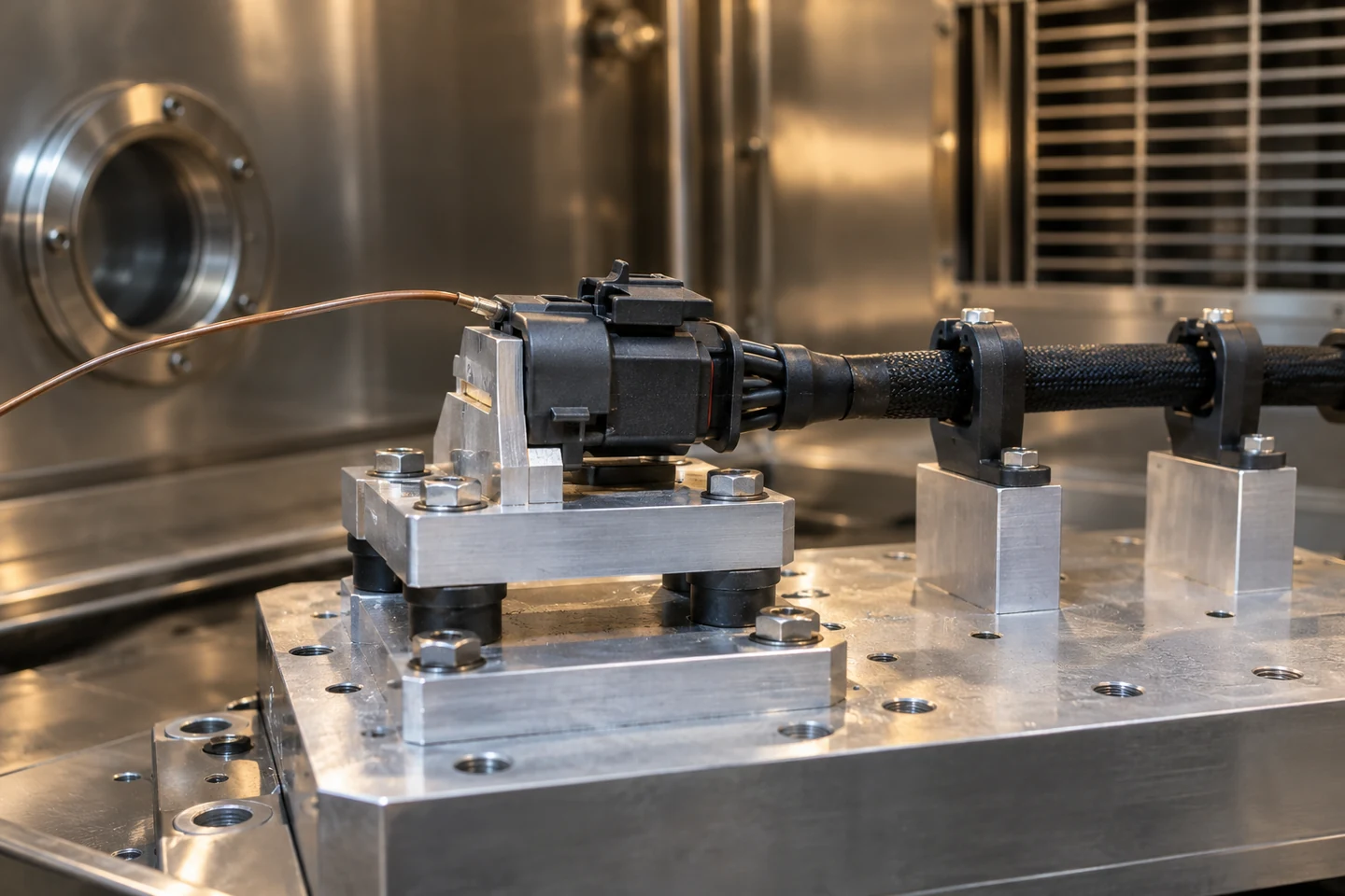
VALIDATION / 장착 지그·배선 지지·환경 시험

VALIDATION / 장착 지그·배선 지지·환경 시험

Motion.

시험 입력이 접촉면에서 무엇으로 바뀌는지 확인합니다.

07 / VIBRATION TRANSFER

하네스와 지그가 접점에 전달하는 운동을 확인합니다

커넥터 몸체에 같은 가속도를 주어도 접점의 응답은 달라질 수 있습니다.

케이블의 자유 길이와 질량, 굽힘과 클램프 위치는 커넥터에 전달되는 힘을 바꿉니다. 시험에서 케이블을 지나치게 짧게 고정하면 현장의 반력을 놓칠 수 있고, 과도하게 길게 두면 대표성이 없는 공진을 만들 수 있습니다. 실제 장착 도면에 맞춘 지지 조건을 명시합니다.

가진 제어점과 시편의 응답점은 다릅니다. 지그의 강성·공진·체결 상태가 입력을 증폭하거나 약화할 수 있으므로, 제어 가속도와 단자 부근의 응답을 함께 점검합니다. 필요하면 축별 전달 특성과 상대 운동을 계측하여 시험의 대표성을 확인합니다.

진동 중 저항 사건이 특정 주파수나 배선 방향에 집중된다면 표면 재료 변경 전에 운동 경로를 조사합니다. 잠금 유격·단자 유지력·하네스 지지를 수정한 후 같은 시험을 반복하면 원인에 맞는 개선인지 판단하기 쉽습니다.

하네스

자유 길이·클램프·굽힘을 재현합니다.

지그

체결·강성·공진과 제어점을 확인합니다.

계면 응답

저항 사건과 국부 상대 운동을 연결합니다.

커넥터 몸체에 같은 가속도를 주어도 접점의 응답은 달라질 수 있습니다.

케이블 교체의 영향

전선 단면이나 외피가 바뀌면 하네스 강성과 질량도 달라질 수 있습니다. 전기 사양이 같아도 진동 입력 전달이 바뀌는 변경인지 검토합니다.

하네스와 지그가 접점에 전달하는 운동을 확인합니다 — 검토 항목

검토 항목영향·조건설계·검증 연결
배선 지지위치·길이·질량현장 반력 재현
시편 장착방향·고정·체결경계조건 일치
가진 전달제어점·응답점증폭·공진 확인
원인 재현주파수·축·배선 방향구조 개선 전후 비교

배선 지지

영향·조건
위치·길이·질량

설계·검증 연결
현장 반력 재현

시편 장착

영향·조건
방향·고정·체결

설계·검증 연결
경계조건 일치

가진 전달

영향·조건
제어점·응답점

설계·검증 연결
증폭·공진 확인

원인 재현

영향·조건
주파수·축·배선 방향

설계·검증 연결
구조 개선 전후 비교

3D · 미동·접촉력·저항의 연결

PROCESS & VALIDATION
ID SOLUTECH / 02
인터랙티브 3D를 준비하고 있습니다.
마모 트랙

접촉 트랙에서 마모·산화막·파편이 축적될 수 있습니다.

드래그·방향키: 회전 / + −: 확대·축소 / Home: 초기화미동·접촉력·저항의 연결
08 / COUPLED DEGRADATION

발열·힘 저하·미세 운동을 함께 추적합니다

서로 연결된 열화 경로를 하나의 단순 가속계수로 줄이지 않습니다.

저항 상승은 같은 전류에서 손실을 증가시키고 온도 변화를 만들 수 있습니다. 고온 노출은 스프링의 잔류 힘과 수지·실의 상태를 바꿀 수 있어 계면 운동과 다시 연결됩니다. 다만 실제 열화의 방향과 크기는 방열, 하중과 소재 조합에 달려 있으므로 단정적인 수명 식을 적용하지 않습니다.

온도 사이클은 서로 다른 재료의 열팽창 차이를 통해 상대 운동을 만들 수 있습니다. 진동·열·습도를 별도로 통과한 결과만으로 복합 노출을 자동 합격 처리하지 않고, 사용 이력에서 동시에 또는 순차로 발생하는 조건을 시험 계획에 반영합니다.

시험 순서도 결과의 일부입니다. 먼저 마모된 표면에 환경을 가하는 경우와 먼저 부식된 계면을 움직이는 경우는 같은 상태에서 출발하지 않습니다. 비교 시험은 전처리와 순서를 일치시키고 실제 제품의 위험한 경로를 따로 검토합니다.

P = I²R

정의한 저항 구간의 손실 관계입니다. R과 온도·접촉력은 상태에 따라 변할 수 있으며 이 식 하나로 커넥터 온도나 수명을 예측하지 않습니다.

복합 시험의 목적

복합 시험은 무조건 더 가혹하게 만드는 절차가 아닙니다. 실제로 만나는 열·운동·습기 이력과 고장 기전을 재현하도록 수준과 순서를 정해야 원인과 개선을 설명할 수 있습니다.

발열·힘 저하·미세 운동을 함께 추적합니다 — 검토 항목

검토 항목영향·조건설계·검증 연결
전류와 열손실·방열·주기온도 응답 기록
열과 힘이완·팽창·수지 변화잔류 힘과 위치
운동과 표면마모·노출·잔해저항 사건 대응
복합 시험순서·동시성·회복사용 이력과 연결

전류와 열

영향·조건
손실·방열·주기

설계·검증 연결
온도 응답 기록

열과 힘

영향·조건
이완·팽창·수지 변화

설계·검증 연결
잔류 힘과 위치

운동과 표면

영향·조건
마모·노출·잔해

설계·검증 연결
저항 사건 대응

복합 시험

영향·조건
순서·동시성·회복

설계·검증 연결
사용 이력과 연결

계면의 움직임을 줄여야
표면의 변화를
제어할 수 있습니다.

Assembly.

단자 밖의 계면과 공정 변동도 연결 품질에 포함합니다.

09 / SEALING AND TERMINATION

밀봉과 크림프는 접촉면 밖의 실패 경로를 막습니다

완전 결합·실 압축·전선 고정을 함께 확인해야 합니다.

하우징 실과 전선 실은 물과 오염물의 유입 경로를 제어합니다. 실의 위치·압축과 전선 외경이 어긋나면 소재 자체가 적합해도 조립체의 밀봉 기능이 달라질 수 있습니다. 단자 삽입과 후방 잠금 상태를 확인하고 손상·비틀림·이물질을 검사합니다.

크림프는 도체와 단자를 연결하는 별도의 계면입니다. 압착 높이와 폭, 도체 가닥 상태와 절연 지지는 서로 다른 정보를 주므로 인장 시험 하나로 전기적 품질을 대신하지 않습니다. 단자·전선·공구 조합별 승인 조건과 작업 기록이 필요합니다.

습기·세정제·오일 등 실제 노출을 고려하되 모든 조건을 같은 염수분무 시간으로 대표하지 않습니다. 인공 부식시험은 정의한 조건의 비교 자료이며 현장 사용 연수로 자동 환산할 수 없습니다. 밀봉 상태와 전기 기능은 환경 노출 전후 같은 방법으로 확인합니다.

완전 결합·실 압축·전선 고정을 함께 확인해야 합니다.

삽입 완료를 확인합니다

하우징 잠금과 단자 후방 잠금은 서로 다른 기능일 수 있습니다. 외부 래치가 닫혀 있어도 단자가 뒤로 밀리는 상태가 없는지 유지력과 삽입 위치로 확인합니다.

밀봉과 크림프는 접촉면 밖의 실패 경로를 막습니다 — 검토 항목

검토 항목영향·조건설계·검증 연결
하우징 실위치·압축·완전 결합누설·외관·치수
전선 실외경·손상·삽입후방 유입 경로
도체 크림프가닥·압착 형상·공구단면·인장·전압 강하
환경 노출물·염·유체·온도밀봉과 회로 기능

하우징 실

영향·조건
위치·압축·완전 결합

설계·검증 연결
누설·외관·치수

전선 실

영향·조건
외경·손상·삽입

설계·검증 연결
후방 유입 경로

도체 크림프

영향·조건
가닥·압착 형상·공구

설계·검증 연결
단면·인장·전압 강하

환경 노출

영향·조건
물·염·유체·온도

설계·검증 연결
밀봉과 회로 기능

10 / CURRENT AND TEMPERATURE

전류 용량은 배선과 장착 상태에서 확인합니다

같은 단자라도 전선·주위 온도·인접 회로의 발열에 따라 온도가 달라집니다.

단자 데이터의 전류값은 정해진 조건에서 얻은 결과입니다. 실제 하우징의 사용 회로 수, 전선 단면과 길이, 인접 단자의 동시 통전과 주위 온도는 발열과 방열 조건을 바꿉니다. 단자 하나의 시험값을 다극 하우징 전체의 연속 사용 전류로 그대로 옮기지 않습니다.

온도 측정 위치는 접촉부·크림프·전선과 하우징에서 각각 다른 정보를 줍니다. 센서 부착이 열 흐름이나 움직임을 지나치게 바꾸지 않도록 하고, 열 안정 상태의 정의와 부하 주기를 지정합니다. 외부 표면 온도가 낮다고 내부 접촉부의 최고 온도까지 낮다고 단정할 수 없습니다.

전기적 가열 시험 후에는 접촉력과 실·수지의 상태, 전압 강하를 다시 확인합니다. 연결부의 사용 한계는 도체만이 아니라 단자·도금·하우징·실의 허용 조건이 함께 결정하므로, 온도와 기능을 모두 만족하는 장착 구성을 승인합니다.

배선 조건

단면·길이·하우징 사용 회로를 기록합니다.

온도 계측

측정 위치·안정화·센서 영향을 정의합니다.

기능 확인

열 노출 후 힘·밀봉·저항을 재평가합니다.

다극 통전 조건

사용하지 않는 회로가 많은 시험 시편과 모든 회로가 통전되는 실제 장치는 방열 조건이 다를 수 있습니다. 회로별 전류와 인접 열원을 시험 정의에 포함합니다.

전류 용량은 배선과 장착 상태에서 확인합니다 — 검토 항목

검토 항목영향·조건설계·검증 연결
전선 구성단면·길이·피복열 경로와 허용 조건
회로 구성동시 통전·인접 발열다극 하우징 조건
온도 측정접촉부·크림프·외면위치별 차이와 안정화
사용 한계소재·도금·수지·실온도와 기능 동시 판정

전선 구성

영향·조건
단면·길이·피복

설계·검증 연결
열 경로와 허용 조건

회로 구성

영향·조건
동시 통전·인접 발열

설계·검증 연결
다극 하우징 조건

온도 측정

영향·조건
접촉부·크림프·외면

설계·검증 연결
위치별 차이와 안정화

사용 한계

영향·조건
소재·도금·수지·실

설계·검증 연결
온도와 기능 동시 판정

Validation.

실패의 재현성과 개선의 효과를 같은 조건에서 확인합니다.

11 / TEST SCOPE

규격의 이름보다 판본·범위·시험 구성을 명확히 합니다

시험 표준은 장착 조건과 합격 기준을 대신 정해주지 않습니다.

SAE/USCAR-2는 자동차 전기 접속 시스템을 평가하는 대표 자료이며 공식 범위는 저전압 도로 차량용 단자·커넥터를 구분합니다. 인용할 때에는 적용 판본과 커넥터 종류를 명시하고, 범위 밖의 고전압·다른 단자 형식으로 자동 확장하지 않습니다.

ISO 16750-3과 -4는 차량의 기계적·기후 하중 검토에 유용합니다. 장착 위치에 따른 환경과 시스템 범위를 다루므로 모든 커넥터에 같은 진동 레벨이나 온도를 요구한다고 읽지 않습니다. 구체적인 수치와 시험 순서는 정식 적용 규격 및 고객 요구로 확정합니다.

검증 표에는 시편 수, 배선·장착, 통전·측정, 전처리·순서, 사건 판정과 종료 후 검사를 함께 적습니다. 서로 다른 규격의 가장 높은 숫자만 조합하면 실제 사용과 무관한 시험이 될 수 있어, 기능과 고장 기전에 근거해 시험을 선택합니다.

범위

전압·단자 형식·장착 위치를 확인합니다.

판본

적용 개정과 고객 요구를 기록합니다.

시험 정의

시편·배선·순서·판정을 하나로 묶습니다.

공개 규격 범위와 적용 판본을 확인했으며, 상세 유료 규정의 시험 수치나 합격값을 임의로 재현하지 않습니다.

공식 범위와 상세 요구

공개 규격 설명은 적용 범위를 확인하는 자료입니다. 실제 시험의 수치·순서·합격값은 적용 판본의 정식 문서와 고객 사양에서 확인하고 시험 의뢰서에 명시합니다.

규격의 이름보다 판본·범위·시험 구성을 명확히 합니다 — 검토 항목

검토 항목영향·조건설계·검증 연결
USCAR-2적용 전압·커넥터 형식범위 밖 확장 금지
ISO 16750-3기계적 하중·장착 위치진동·충격 계획
ISO 16750-4기후 하중·설치 환경열·환경 계획
고객 사양기능·순서·합격 한계승인 기준 확정

USCAR-2

영향·조건
적용 전압·커넥터 형식

설계·검증 연결
범위 밖 확장 금지

ISO 16750-3

영향·조건
기계적 하중·장착 위치

설계·검증 연결
진동·충격 계획

ISO 16750-4

영향·조건
기후 하중·설치 환경

설계·검증 연결
열·환경 계획

고객 사양

영향·조건
기능·순서·합격 한계

설계·검증 연결
승인 기준 확정

12 / ROOT CAUSE

재결합 전의 증거로 고장 원인을 좁힙니다

전기 데이터와 기계·표면 관찰을 같은 시편 이력에서 연결합니다.

간헐 고장은 커넥터를 만지거나 분리하는 과정에서 잠시 사라질 수 있습니다. 고장 발생 위치와 온도, 배선 자세, 전압·전류 파형을 우선 기록하고, 외부 하네스 손상과 잠금 상태를 보존한 채 비파괴 확인을 진행합니다. 원인을 보기 전에 원래 상태를 바꾸지 않는 순서가 중요합니다.

전기 경로를 구간별로 나누어 접촉면, 크림프와 전선의 기여를 비교합니다. 이후 접촉력·유지력·마모 자국·도금과 오염·단면을 확인하면 시험 중 사건과 물리적 흔적이 연결됩니다. 같은 현상을 만들 수 있는 여러 원인을 한 장의 표면 사진으로 단정하지 않습니다.

재료·도금·공구·하네스 지지·잠금 형상을 변경한 뒤에는 해당 고장 경로를 대표하는 시험으로 효과를 확인합니다. 아이디솔루텍 검토에는 커넥터 도면, 단자·전선 조합, 실제 설치 사진과 하중 이력, 실패 파형·시편 및 승인 기준을 함께 제공하면 분석과 개선 범위를 명확히 정할 수 있습니다.

증거 보존

재결합 전 설치·파형·사건을 남깁니다.

구간 분석

접촉면·크림프·전선의 기여를 나눕니다.

개선 승인

변경한 원인 경로를 재현하여 검증합니다.

시편 이력의 연속성

전기 사건을 기록한 시편과 단면 분석 시편의 관계가 끊기면 원인을 단정하기 어렵습니다. 시편 식별, 시험 이력과 분해 순서를 유지하고 재시험품을 원래 시편과 구분합니다.

재결합 전의 증거로 고장 원인을 좁힙니다 — 검토 항목

검토 항목영향·조건설계·검증 연결
현장 기록온도·자세·발생 조건재현 가능한 사건 정의
비파괴 검사잠금·배선·구간 저항상태 보존과 원인 분리
분해 분석힘·표면·도금·크림프물리 흔적과 파형 연결
변경 검증소재·공정·지지·잠금원인별 재시험과 추적

현장 기록

영향·조건
온도·자세·발생 조건

설계·검증 연결
재현 가능한 사건 정의

비파괴 검사

영향·조건
잠금·배선·구간 저항

설계·검증 연결
상태 보존과 원인 분리

분해 분석

영향·조건
힘·표면·도금·크림프

설계·검증 연결
물리 흔적과 파형 연결

변경 검증

영향·조건
소재·공정·지지·잠금

설계·검증 연결
원인별 재시험과 추적

고장 원인은
재결합 전의 증거에
남아 있습니다.

Start a
Project.

단자·하네스의 설계와 신뢰성 검증 조건을 함께 검토합니다.

Review terminal and harness design together with reliability validation conditions.

개발 상담 · Contact

기술 협의 · Engineering Consultation
도면과 사양을 기준으로 소재·가공·표면처리,
주요 품질 항목과 공급 조건을 함께 검토합니다.


We review drawings and specifications to define materials, manufacturing methods, surface finishes, key quality requirements, and supply conditions.

개발 의뢰하기 · Development Inquiry

    도면 및 기술자료
    Drawings & Technical Documents

    도면 번호와 개정 이력이 표시된 2D·3D 도면을 첨부해 주세요.
    사양서와 검사 기준도 함께 전달할 수 있습니다.
    Attach your 2D or 3D drawings with their drawing numbers and revisions.
    Include specifications and inspection criteria as needed.

    파일을 이곳에 놓아주세요Drag & drop your files here

    선택된 파일 없음 / No files attached

    최대 5개 · 파일당 5MB · 총 15MB / Up to 5 files · 5MB each · 15MB total
    PDF · DWG · DXF · STEP/STP · IGS/IGES · JPG · PNG · ZIP

    * 필수 입력 / Required fields

    AUTOMOTIVE CONTACT RELIABILITY

    CONNECTOR SYSTEM / 밀봉 하우징과 단자 결합 구조

    Reliable Connections.

    Connect interface stability with harness, environment and assembly conditions.

    VIBRATION · THERMAL · FRETTING · TEST

    ENGLISH EDITION

    Automotive Contacts
    Engineered for Reliability

    Connecting vibration, thermal history, fretting and resistance verification

    Stable contact.
    Through every cycle.

    An automotive connection problem may remain invisible at rest. Brief interruptions, force loss after heat exposure and micromotion-driven surface changes can disturb circuit function intermittently.

    This article connects terminal geometry and material with housing, seals, crimps and harness restraint to support design and validation decisions. It defines voltage class, mounting location and measurement conditions to follow the connection from initial resistance through combined exposure.

    COMPONENTS / 하우징·잠금·암단자·수단자

    COMPONENTS / Housing, locking, receptacles and blades

    System.

    Use actual installation as the common basis for design and testing.

    01 / SYSTEM BOUNDARY

    Contact Reliability Extends from Terminals to Harness Support

    Vehicle vibration, temperature and moisture reach the interface through different paths.

    An automotive connection is maintained by the terminal interface, crimp and wire, housing and latch, seals and harness restraint. Looking only at the contact spot can miss causes introduced by housing clearance or cable motion. Begin with circuit function—sensor, power or communication—and the actual installation location.

    Engine-adjacent, cabin, door and underbody locations have different temperature histories, vibration inputs and exposures. Even with identical terminals, harness length, support positions and orientation can change relative motion at the interface. Treat part number and installation arrangement as one test definition.

    This article addresses contact stability in separable automotive connections. Low-voltage connector requirements cannot simply be extended to high-voltage propulsion systems. High-speed signal integrity and high-voltage insulation need their own system-specific verification.

    Connection boundary

    Connect terminal, crimp, wire, housing and seal.

    Installation

    Record actual temperature, vibration and harness support.

    Circuit function

    Select acceptance for signal, power and voltage class.

    Contact Reliability Extends from Terminals to Harness Support — Review Items

    Review itemInfluence or conditionDesign and verification
    Electrical pathInterface, crimp and wireDefine measurement span and function
    Mechanical pathHousing, locking and harnessRelative motion and retention
    Environmental pathSeals, venting, temperature and exposureInstallation-specific testing

    Electrical path

    Influence or condition
    Interface, crimp and wire

    Design and verification
    Define measurement span and function

    Mechanical path

    Influence or condition
    Housing, locking and harness

    Design and verification
    Relative motion and retention

    Environmental path

    Influence or condition
    Seals, venting, temperature and exposure

    Design and verification
    Installation-specific testing

    02 / ELECTRICAL FAILURE

    Mean Resistance and Intermittency Reveal Different Problems

    First establish whether measurement timing can resolve a functional failure.

    Low static resistance can coexist with brief interruptions or resistance excursions during vibration. Averaging and logging intervals longer than the event can hide it, so define permissible interruption duration and detection conditions before the test.

    Voltage drop may include crimp and wire resistance as well as the terminal interface. A four-wire arrangement with separate current and voltage connections still cannot isolate causes if its sensing span is inappropriate. Define interface comparison and whole-connection evaluation as distinct channels or tests.

    Synchronize events with excitation axis, frequency, temperature and electrical loading. A normal value after remating may represent an altered interface rather than demonstrated recovery. Preserve original-state evidence before disconnecting and reconnecting.

    Static value

    Measure baseline resistance over a defined span.

    Dynamic event

    Specify timing, threshold and duration.

    Preserve condition

    Record waveform and installation before remating.

    First establish whether measurement timing can resolve a functional failure.

    Validate the detection chain

    Measurement slower than the events of interest can miss abnormalities. Check detection delay and storage with known test signals and document filters and averaging settings.

    Mean Resistance and Intermittency Reveal Different Problems — Review Items

    Review itemInfluence or conditionDesign and verification
    Contact resistanceCurrent and voltage pickup positionsSeparate interface and crimp
    InterruptionThreshold, sampling and bandwidthRelate to circuit function
    Event historyTemperature, excitation and powerReproduction and synchronized diagnosis

    Contact resistance

    Influence or condition
    Current and voltage pickup positions

    Design and verification
    Separate interface and crimp

    Interruption

    Influence or condition
    Threshold, sampling and bandwidth

    Design and verification
    Relate to circuit function

    Event history

    Influence or condition
    Temperature, excitation and power

    Design and verification
    Reproduction and synchronized diagnosis

    Interface.

    Connect surface change and mechanical motion in one causal chain.

    03 / FRETTING MECHANISM

    Small Repeated Motion Continuously Changes the Interface

    Fretting is governed by actual interface motion, not vibration amplitude alone.

    Fretting accumulates wear and surface changes through small repeated motion between contacting surfaces. In tin-based interfaces, debris and oxidation can destabilize conductive paths. Noble finishes can also wear through and expose underlayers, creating an interface different from its initial condition.

    Test-table displacement is not necessarily the slip at the contact spot. Housing and terminal elasticity, friction and restraint distribute motion, so inspect relative movement near the terminals where practicable. Select measurement locations and resolution that reveal movement at the actual interface.

    A visible wear scar alone does not establish electrical failure. Connect resistance events with debris distribution, exposed plating locations and force changes to decide whether motion control, a surface change or harness restraint addresses the cause.

    Relative motion

    Distinguish housing motion from contact-spot motion.

    Surface change

    Examine wear, oxidation and exposed underlayers.

    Failure link

    Interpret resistance events with wear location.

    Resistance after motion stops

    Once vibration stops, contact spots can stabilize and resistance may decrease again. Retain end-of-test readings and in-test waveforms as distinct observations to capture intermittent behavior.

    Small Repeated Motion Continuously Changes the Interface — Review Items

    Review itemInfluence or conditionDesign and verification
    Motion inputVibration, expansion and wire reactionVerify interface displacement
    Wear debrisFormation, movement and accumulationSurface and compositional examination
    Finish exposureTin, noble finish and underlayerFinal interface state
    Electrical changeExcursions, interruption and recoveryRelate waveform and damage

    Motion input

    Influence or condition
    Vibration, expansion and wire reaction

    Design and verification
    Verify interface displacement

    Wear debris

    Influence or condition
    Formation, movement and accumulation

    Design and verification
    Surface and compositional examination

    Finish exposure

    Influence or condition
    Tin, noble finish and underlayer

    Design and verification
    Final interface state

    Electrical change

    Influence or condition
    Excursions, interruption and recovery

    Design and verification
    Relate waveform and damage

    CONTACT INTERFACE / 스프링 빔과 블레이드의 접촉 구조

    CONTACT INTERFACE / Spring beams and mating blade

    04 / SPRING CONTACT DESIGN

    Contact Force Results from Geometry, Temper and Working Travel

    Increasing force must be weighed against insertion effort, wear and stress margin.

    A receptacle beam develops normal force as the blade deflects it during insertion. Beam length, thickness, bend radii, material condition and actual insertion geometry jointly determine force–travel behavior. Review minimum and maximum tolerance combinations rather than inferring force from nominal clearance alone.

    Greater force may support electrical stability and motion restraint under some conditions, but it can also increase insertion load, wear and beam stress. Permanent deformation from overtravel or angled assembly should be distinguished from normal operating deflection.

    Separating contact-spring and locating functions can allow wire or housing movement to be absorbed away from the contact spot. TE’s separate positioning-spring example illustrates motion-path control, but performance cannot be transferred to another geometry without physical validation.

    Increasing force must be weighed against insertion effort, wear and stress margin.

    Contact Force Results from Geometry, Temper and Working Travel — Review Items

    Review itemInfluence or conditionDesign and verification
    Beam geometryLength, thickness and curvatureForce–travel and stress
    Mating terminalThickness, position and engagementTolerance combinations
    AssemblyAngle, overtravel and rateDamage and insertion effort
    Location controlSpring, latch and supportInterface relative movement

    Beam geometry

    Influence or condition
    Length, thickness and curvature

    Design and verification
    Force–travel and stress

    Mating terminal

    Influence or condition
    Thickness, position and engagement

    Design and verification
    Tolerance combinations

    Assembly

    Influence or condition
    Angle, overtravel and rate

    Design and verification
    Damage and insertion effort

    Location control

    Influence or condition
    Spring, latch and support

    Design and verification
    Interface relative movement

    3D · Crimp and contact architecture of an automotive terminal

    STRUCTURE & INTERFACE
    ID SOLUTECH / 01
    Preparing interactive 3D.
    Crimp and mate

    Check crimp height, width and cross-section with the specified tooling and actual conductor.

    Drag / arrow keys: rotate · + −: zoom · Home: resetCrimp and contact architecture of an automotive terminal

    A normal static reading
    does not establish
    in-service stability.

    Thermal.

    Validate the link between thermal history and retained force.

    05 / THERMAL RELAXATION

    Verify the Force Remaining after Thermal Exposure

    Initial hardness and strength do not establish long-term force retention.

    Stress relaxation reduces the force of a constrained spring with time and temperature. Copper-alloy family, temper, initial stress, orientation and manufacturing thermal history all matter; the alloy name alone cannot predict retained force. Use evidence representative of the actual formed condition.

    Constant-temperature material exposure and a vehicle’s varying thermal history are not equivalent. Ambient heat combines with electrical self-heating, cooling conditions and duty cycle. Define time history and installation rather than comparing only the service maximum with a material-table temperature.

    Measure force, permanent set, insertion and withdrawal response and resistance before and after exposure. Mixing hot measurements with values after return to room temperature obscures reversible temperature effects and permanent degradation, so identify the measurement state in the report.

    Material condition

    Verify alloy, temper, orientation and thermal history.

    Temperature history

    Combine ambient exposure with self-heating.

    Retained function

    Assess force, set and resistance after exposure.

    Material coupons and assemblies

    Stress-relaxation data from material coupons help screen alloys. Formed terminals also carry shaping, plating and insertion histories, so use assembly force-retention testing to complete the decision.

    Verify the Force Remaining after Thermal Exposure — Review Items

    Review itemInfluence or conditionDesign and verification
    Initial stressForming and insertion travelRelate to material test
    ExposureTemperature, time and electrical loadRepresent thermal history
    Measurement stateHot or returned to ambientSeparate reversible and retained changes
    End pointMinimum force, resistance and damageLink to function

    Initial stress

    Influence or condition
    Forming and insertion travel

    Design and verification
    Relate to material test

    Exposure

    Influence or condition
    Temperature, time and electrical load

    Design and verification
    Represent thermal history

    Measurement state

    Influence or condition
    Hot or returned to ambient

    Design and verification
    Separate reversible and retained changes

    End point

    Influence or condition
    Minimum force, resistance and damage

    Design and verification
    Link to function

    06 / PLATING AND LUBRICATION

    Qualify Plating and Lubrication as an Interface System

    A finish name or the presence of lubricant is not a complete fretting strategy.

    Tin, silver or gold finishes should be selected for current, signal level, mating cycles and environment. Identical finish names can conceal different thickness, hardness, underlayers, pores and exposed edges. Connect the mating finish combination and actual contact location to the drawing.

    Lubrication can alter friction, wear, oxidation and debris movement. Swingler’s experiments observed benefits under defined interface conditions, not for every grease and terminal. Validate compatibility, quantity, migration, ageing and effects on seals together.

    Lower insertion effort after a finish or lubricant change does not establish better overall contact reliability. Compare assembly effort, endurance and post-environment resistance, and confirm that production leaves the approved condition at the actual contact region.

    Finish pair

    Specify mating face, underlayer and contact location.

    Lubrication

    Verify type, quantity, ageing and compatibility.

    Process repeatability

    Compare approved and production interface condition.

    Application-process uniformity

    Lubrication depends on the amount and distribution actually retained at the interface, not only the product name. Reproduce the approved state through dispensing, handling, storage and migration during mating.

    Qualify Plating and Lubrication as an Interface System — Review Items

    Review itemInfluence or conditionDesign and verification
    Top finishMaterial, thickness and hardnessWear and electrical function
    UnderlayerDiffusion, corrosion and exposureState after damage
    LubricantRheology, compatibility and migrationCompare after thermal/environmental exposure
    Process conditionCleaning, application and packagingReproduce actual contact region

    Top finish

    Influence or condition
    Material, thickness and hardness

    Design and verification
    Wear and electrical function

    Underlayer

    Influence or condition
    Diffusion, corrosion and exposure

    Design and verification
    State after damage

    Lubricant

    Influence or condition
    Rheology, compatibility and migration

    Design and verification
    Compare after thermal/environmental exposure

    Process condition

    Influence or condition
    Cleaning, application and packaging

    Design and verification
    Reproduce actual contact region

    VALIDATION / 장착 지그·배선 지지·환경 시험

    VALIDATION / Fixture, harness restraint and environment

    Motion.

    Identify how the test input becomes motion at the interface.

    07 / VIBRATION TRANSFER

    Verify Motion Transmitted through Harness and Fixture

    Equal housing acceleration can produce different contact responses.

    Free cable length, mass, bends and clamp positions change forces transmitted to a connector. An excessively short restraint can suppress field reactions, while an unrealistic free span can introduce irrelevant resonances. Specify supports from the actual installation drawing.

    Excitation control and specimen response are different measurement locations. Fixture stiffness, resonance and fastening can amplify or attenuate input, so examine control acceleration and response near the terminals. Where needed, measure axis-dependent transfer and relative motion to establish representativeness.

    If resistance events cluster at a frequency or cable orientation, investigate the motion path before changing the finish. Repeating the same test after changes to latch clearance, terminal retention or harness support helps determine whether the remedy addresses the cause.

    Harness

    Reproduce free length, clamps and bends.

    Fixture

    Review fastening, stiffness, resonance and control point.

    Interface response

    Connect resistance events with local relative motion.

    Equal housing acceleration can produce different contact responses.

    Effects of cable substitution

    Changing conductor section or insulation can alter harness stiffness and mass. Even if electrical requirements remain the same, review whether the substitution changes vibration transfer.

    Verify Motion Transmitted through Harness and Fixture — Review Items

    Review itemInfluence or conditionDesign and verification
    Cable supportPosition, length and massReproduce service reaction
    MountingOrientation, restraint and fasteningMatch boundary conditions
    Excitation transferControl and response pointsCheck amplification and resonance
    Cause reproductionFrequency, axis and cable directionCompare before/after structural changes

    Cable support

    Influence or condition
    Position, length and mass

    Design and verification
    Reproduce service reaction

    Mounting

    Influence or condition
    Orientation, restraint and fastening

    Design and verification
    Match boundary conditions

    Excitation transfer

    Influence or condition
    Control and response points

    Design and verification
    Check amplification and resonance

    Cause reproduction

    Influence or condition
    Frequency, axis and cable direction

    Design and verification
    Compare before/after structural changes

    3D · Micromotion, normal force and resistance

    PROCESS & VALIDATION
    ID SOLUTECH / 02
    Preparing interactive 3D.
    Wear track

    Wear, oxide films and debris can develop within the contact track.

    Drag / arrow keys: rotate · + −: zoom · Home: resetMicromotion, normal force and resistance
    08 / COUPLED DEGRADATION

    Track Heating, Force Loss and Micromotion Together

    Do not reduce coupled degradation to one assumed acceleration factor.

    A resistance rise increases dissipation at the same current and can change temperature. Thermal exposure can alter retained spring force, polymer and seal condition, feeding back into interface motion. The direction and magnitude depend on cooling, loading and material combinations, so avoid a universal life equation.

    Thermal cycling can create relative motion through differential expansion. Passing separate vibration, thermal and humidity tests does not automatically qualify combined exposure. Reflect conditions occurring simultaneously or sequentially in the service history.

    Test order is part of the result. Environmental exposure after wear and motion after corrosion do not start from the same surface state. Align preconditioning and sequence in comparisons, and review the damaging paths relevant to the product separately.

    P = I²R

    This is the dissipation relation for a defined resistive span. Resistance, temperature and force can change with state; this equation alone does not predict connector temperature or life.

    Purpose of combined testing

    Combined testing is not simply a way to maximize severity. Set levels and sequence to reproduce relevant heat, motion, moisture and failure mechanisms so that causes and improvements remain interpretable.

    Track Heating, Force Loss and Micromotion Together — Review Items

    Review itemInfluence or conditionDesign and verification
    Current and heatDissipation, cooling and dutyRecord thermal response
    Heat and forceRelaxation, expansion and polymer changeRetained force and position
    Motion and surfaceWear, exposure and debrisRelate to resistance events
    Combined testingOrder, simultaneity and recoveryConnect to service history

    Current and heat

    Influence or condition
    Dissipation, cooling and duty

    Design and verification
    Record thermal response

    Heat and force

    Influence or condition
    Relaxation, expansion and polymer change

    Design and verification
    Retained force and position

    Motion and surface

    Influence or condition
    Wear, exposure and debris

    Design and verification
    Relate to resistance events

    Combined testing

    Influence or condition
    Order, simultaneity and recovery

    Design and verification
    Connect to service history

    Control interface motion
    to manage
    surface change.

    Assembly.

    Include interfaces and process variation beyond the mating terminals.

    09 / SEALING AND TERMINATION

    Sealing and Termination Control Failures Outside the Mating Interface

    Verify full mating, seal compression and wire restraint together.

    Housing and wire seals control ingress paths for water and contamination. Misaligned seals, inappropriate compression or mismatched wire diameter can change sealing even when the material itself is suitable. Verify terminal insertion and secondary locking and inspect damage, twisting and foreign material.

    A crimp is a separate interface between conductor and terminal. Crimp height and width, strand condition and insulation support provide different evidence; a pull test alone cannot replace electrical qualification. Approved terminal–wire–tool combinations and process records are needed.

    Consider actual moisture, cleaners and oils rather than representing every exposure with one salt-spray duration. Artificial corrosion tests compare defined conditions and cannot automatically predict field years. Verify sealing and electrical function by matching methods before and after exposure.

    Verify full mating, seal compression and wire restraint together.

    Verify completed insertion

    Housing latching and terminal secondary locking may serve different functions. Even with the external latch closed, verify insertion position and retention to exclude terminal pushback.

    Sealing and Termination Control Failures Outside the Mating Interface — Review Items

    Review itemInfluence or conditionDesign and verification
    Housing sealPosition, compression and full matingLeakage, appearance and geometry
    Wire sealDiameter, damage and insertionRear ingress path
    Conductor crimpStrands, crimp form and toolingSection, pull and voltage drop
    ExposureWater, salt, fluids and temperatureSeal and circuit function

    Housing seal

    Influence or condition
    Position, compression and full mating

    Design and verification
    Leakage, appearance and geometry

    Wire seal

    Influence or condition
    Diameter, damage and insertion

    Design and verification
    Rear ingress path

    Conductor crimp

    Influence or condition
    Strands, crimp form and tooling

    Design and verification
    Section, pull and voltage drop

    Exposure

    Influence or condition
    Water, salt, fluids and temperature

    Design and verification
    Seal and circuit function

    10 / CURRENT AND TEMPERATURE

    Verify Current Capability in the Installed Wiring Configuration

    Terminal temperature changes with wire, ambient conditions and neighboring loaded circuits.

    A terminal current value represents defined test conditions. The number of loaded cavities, conductor section and length, neighboring powered terminals and ambient temperature change heating and cooling. Do not transfer a single-terminal test value directly to continuous operation of a populated multipole housing.

    Temperature at the contact, crimp, wire and housing provides different information. Attach sensors without unduly changing heat flow or movement, and define thermal stabilization and load duty. A modest external surface temperature does not establish the peak temperature inside the contact region.

    After electrical heating, recheck force, seals, polymer condition and voltage drop. Operating limits depend on the allowable conditions of terminal, finish, housing and seal as well as the conductor. Qualify an installation that meets both temperature and functional requirements.

    Wiring conditions

    Record section, length and populated circuits.

    Temperature measurement

    Define location, stabilization and sensor effects.

    Functional check

    Reassess force, sealing and resistance after heating.

    Populated-circuit loading

    A specimen with few powered cavities can cool differently from an assembly with many loaded circuits. Include per-circuit currents and nearby heat sources in the test definition.

    Verify Current Capability in the Installed Wiring Configuration — Review Items

    Review itemInfluence or conditionDesign and verification
    Wire arrangementSection, length and insulationThermal path and allowable conditions
    Circuit arrangementSimultaneous current and nearby heatPopulated housing conditions
    Temperature sensingContact, crimp and outer surfaceLocation effects and stabilization
    Operating limitMetal, finish, polymer and sealTemperature and function together

    Wire arrangement

    Influence or condition
    Section, length and insulation

    Design and verification
    Thermal path and allowable conditions

    Circuit arrangement

    Influence or condition
    Simultaneous current and nearby heat

    Design and verification
    Populated housing conditions

    Temperature sensing

    Influence or condition
    Contact, crimp and outer surface

    Design and verification
    Location effects and stabilization

    Operating limit

    Influence or condition
    Metal, finish, polymer and seal

    Design and verification
    Temperature and function together

    Validation.

    Verify failure reproduction and improvement under comparable conditions.

    11 / TEST SCOPE

    Specify Edition, Scope and Configuration before the Standard Name

    A test standard does not replace product-specific configuration and acceptance.

    SAE/USCAR-2 is a principal reference for automotive electrical connection testing, with an official scope distinguishing low-voltage road-vehicle terminals and connectors. Identify the applicable revision and connector type, and do not automatically extend it to high voltage or excluded terminal formats.

    ISO 16750-3 and -4 support review of vehicle mechanical and climatic loads. They address environmental conditions by mounting location and system scope rather than prescribing one vibration level or temperature for every connector. Obtain detailed levels and sequences from the formally applicable specification and customer requirements.

    A validation matrix should include specimen count, wiring and mounting, electrical load and measurement, preconditioning and order, event criteria and final inspection. Combining the largest numbers from unrelated standards can create an unrepresentative test; select tests from function and failure mechanism.

    Scope

    Verify voltage, terminal type and location.

    Revision

    Record applicable edition and customer requirements.

    Test definition

    Unite specimens, wiring, sequence and acceptance.

    The public standard scopes and revisions were checked; detailed test levels and acceptance values must come from the applicable authorized specification.

    Public scope and detailed requirements

    Public standard descriptions establish scope. Confirm actual levels, sequence and acceptance from the formally applicable edition and customer specification, then state them in the test request.

    Specify Edition, Scope and Configuration before the Standard Name — Review Items

    Review itemInfluence or conditionDesign and verification
    USCAR-2Applicable voltage and connector typeRespect scope boundaries
    ISO 16750-3Mechanical loads and mounting locationVibration and shock planning
    ISO 16750-4Climatic loads and installationThermal/environmental planning
    Customer specificationFunction, sequence and limitsFinalize approval criteria

    USCAR-2

    Influence or condition
    Applicable voltage and connector type

    Design and verification
    Respect scope boundaries

    ISO 16750-3

    Influence or condition
    Mechanical loads and mounting location

    Design and verification
    Vibration and shock planning

    ISO 16750-4

    Influence or condition
    Climatic loads and installation

    Design and verification
    Thermal/environmental planning

    Customer specification

    Influence or condition
    Function, sequence and limits

    Design and verification
    Finalize approval criteria

    12 / ROOT CAUSE

    Preserve Evidence before Remating to Resolve the Cause

    Connect electrical data with mechanical and surface observations from the same specimen history.

    Intermittency can temporarily disappear when a connector is touched or disconnected. First record location, temperature, cable pose and voltage/current waveforms, then perform nondestructive checks while preserving harness damage and locking state. The sequence should avoid altering the original condition before it is understood.

    Divide the electrical path into interface, crimp and wire contributions. Follow with force, retention, wear marks, plating, contamination and sections to connect test events with physical evidence. Several causes can produce similar symptoms, so one surface image cannot settle the diagnosis.

    After changing material, finish, tooling, harness support or locking geometry, validate the remedy with tests representing the failure path. For an ID SOLUTECH review, provide connector drawings, terminal–wire combinations, actual installation and load history, failed waveforms and samples, and approval criteria to define the investigation.

    Preserve evidence

    Record installation, waveform and events before remating.

    Segment analysis

    Separate interface, crimp and wire contributions.

    Approve improvement

    Reproduce and validate the changed causal path.

    Continuity of specimen history

    Diagnosis becomes uncertain if electrical events cannot be linked to the examined sections. Preserve specimen identification, test history and teardown order, and distinguish retested samples from their original state.

    Preserve Evidence before Remating to Resolve the Cause — Review Items

    Review itemInfluence or conditionDesign and verification
    Field recordTemperature, pose and triggerDefine reproducible event
    Nondestructive checkLocking, wire and segmented resistancePreserve state and isolate cause
    TeardownForce, surfaces, plating and crimpConnect physical evidence with waveforms
    Change validationMaterial, process, support and lockingCause-specific retest and traceability

    Field record

    Influence or condition
    Temperature, pose and trigger

    Design and verification
    Define reproducible event

    Nondestructive check

    Influence or condition
    Locking, wire and segmented resistance

    Design and verification
    Preserve state and isolate cause

    Teardown

    Influence or condition
    Force, surfaces, plating and crimp

    Design and verification
    Connect physical evidence with waveforms

    Change validation

    Influence or condition
    Material, process, support and locking

    Design and verification
    Cause-specific retest and traceability

    Root-cause evidence
    must be preserved
    before remating.

    Electrical Contacts

    Electrical Contacts

    Electrical Contacts

    Electrical Contacts

    Electrical Contacts

    ADDITIONAL INFORMATION

    추가 정보

    핵심 요약

    자동차 접점 신뢰성은 재료와 도금, 접촉력, 하우징·하네스의 운동 전달과 환경 밀봉이 함께 만드는 성능입니다. 정적 저항과 순간 단속을 구분하고 실제 장착·열 이력·측정 범위를 정의한 다음 복합 노출과 원인 분석을 연결해야 합니다.

    핵심 설계·검증 포인트

    01 / 전압 등급·회로 기능·장착 위치와 연결 경계를 먼저 정의합니다.

    02 / 정적 저항과 동적 단속을 구분하고 측정 시간 분해능을 확보합니다.

    03 / 시험대 운동과 접촉점 상대 운동을 동일시하지 않습니다.

    04 / 합금·조질·작동 변위와 열 노출 후 잔류 접촉력을 검증합니다.

    05 / 상대 단자 도금·하부층·윤활을 하나의 조합으로 승인합니다.

    06 / 하네스 지지·밀봉·크림프를 포함한 복합 환경 시험을 계획합니다.

    07 / 재결합 전에 증거를 보존하고 변경한 고장 경로를 재시험합니다.

    FAQ · 자주 묻는 기술 질문

    진동 중 단속이나 열 노출 후 힘 변화가 정지 측정에 나타나지 않을 수 있습니다. 회로가 허용하는 사건 시간에 맞는 계측 대역폭과 문턱값을 정하고 가진·온도·통전 이력과 동기화합니다.

    그렇지 않습니다. 주파수 성분·축·시간과 시편 장착, 하네스 자유 길이·클램프, 지그 응답이 다르면 접촉면 운동이 달라집니다. 제어점과 실제 응답점도 구분해야 합니다.

    일부 조건에서 도움이 되지만 삽입력·마모·스프링 응력과 과변위 손상이 커질 수 있습니다. 힘을 늘리는 접근과 함께 하우징 유격·단자 위치 유지·배선 지지 등 운동 전달 경로를 검토합니다.

    도금 두께·경도·하부층과 접촉 조건에 따라 마모 관통이나 하부층 노출이 발생할 수 있습니다. 귀금속이라는 명칭보다 실제 도금 조합과 환경 후 표면·저항 결과로 판단합니다.

    승인된 단자·도금·수지·실과의 호환성이 필요합니다. 도포량과 위치, 고온에서의 이동·노화 및 잔해 거동을 검증하고 기존 양산 조건을 임의로 변경하지 않습니다.

    적용 범위가 다릅니다. 공식 USCAR-2의 저전압 커넥터 범위를 확인하고 고전압 절연·안전·온도와 기계 요구는 해당 제품에 적용하는 별도 규격 및 고객 사양으로 검증해야 합니다.

    고장 기전과 가속 모델이 검증된 경우에만 그 범위에서 논의할 수 있습니다. 염수분무·진동·온도 시간을 하나의 비율로 사용 연수에 환산하지 않고 실제 조건과 기능 변화의 관계를 확보합니다.

    고장 분석 시에는 재결합이 표면과 잠금 상태를 바꿀 수 있습니다. 먼저 원래 설치 상태·온도·파형·구간별 저항을 기록하고 비파괴 확인 후 정해진 순서로 분해하는 편이 원인 규명에 유리합니다.

    함께 검토할 기술 주제

    접점 프레팅과 표면 시스템

    미세 운동·도금 마모·잔해와 전기적 사건을 함께 해석합니다.

    구리합금 스프링의 힘 유지

    성형 상태·응력·온도·시간이 잔류 접촉력에 미치는 영향을 검증합니다.

    하네스 조립과 환경 검증

    실·크림프·클램프의 설치 상태를 실제 기능 시험과 연결합니다.

    관련 사업분야와 개발 문의

    관련 키워드

    자동차 전기접점커넥터 신뢰성접촉저항순간 단속프레팅 부식응력 이완접촉력진동 전달온도 사이클하네스 지지USCAR-2

    Technical Overview

    Automotive contact reliability emerges from material and plating, normal force, motion transfer through housing and harness, and environmental sealing. Distinguish static resistance from intermittency, define mounting, thermal history and sensing boundaries, then connect combined exposure with root-cause analysis.

    Key Design and Validation Points

    01 / Define voltage class, circuit function, location and connection boundary.

    02 / Separate static resistance from dynamic interruption and provide adequate timing resolution.

    03 / Do not equate table motion with contact-spot relative movement.

    04 / Validate alloy, temper, travel and retained force after thermal exposure.

    05 / Qualify mating finish, underlayer and lubricant as one system.

    06 / Plan combined exposures including harness support, sealing and crimps.

    07 / Preserve evidence before remating and retest the altered failure path.

    FAQ · Technical Questions and Answers

    Vibration-induced interruptions or force changes after heat exposure may not appear in a static reading. Choose bandwidth and thresholds for the circuit’s permissible event duration and synchronize monitoring with excitation, temperature and power.

    No. Frequency content, axis, duration, mounting, free harness length, clamps and fixture response change interface motion. Distinguish the control point from the actual response point.

    It may help under some conditions but can increase insertion effort, wear, spring stress and overtravel damage. Also review housing clearance, terminal location and harness support to control motion transfer.

    Wear-through or underlayer exposure can occur depending on thickness, hardness, underlayer and duty. Judge the actual finish combination and post-exposure surface and resistance evidence, not the noble-metal name alone.

    Compatibility with the approved terminal, finish, polymer and seals is necessary. Validate quantity, location, high-temperature migration, ageing and debris behavior, and control changes to approved production conditions.

    The scopes differ. Check the official low-voltage connector scope and validate high-voltage insulation, safety, thermal and mechanical requirements against the applicable product specifications and customer requirements.

    Only within a validated failure-mechanism and acceleration model. Do not use one ratio to convert salt-spray, vibration or thermal duration into years; establish the relationship between exposure and functional degradation.

    For failure analysis, remating can change surface and locking condition. First preserve installation, temperature, waveforms and segmented resistance; nondestructive checks followed by a controlled teardown sequence better support diagnosis.

    Related Engineering Topics

    Contact fretting and surface systems

    Interpret micromotion, finish wear and debris with electrical events.

    Force retention of copper-alloy springs

    Validate effects of formed state, stress, temperature and time on retained force.

    Harness assembly and environmental validation

    Connect seal, crimp and clamp installation with functional testing.

    Related Capabilities and Development Inquiry

    Related Keywords

    Automotive contactsConnector reliabilityContact resistanceIntermittencyFretting corrosionStress relaxationNormal forceVibration transferThermal cyclingHarness supportUSCAR-2

    Showing 1-6 of 110 results
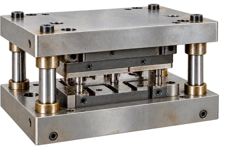
    프레스 금형의 상하형·가이드 포스트·펀치 조립 구조

    프레스 금형 이관: 도면 검토와 보수·개조가 먼저인 이유

    보유한 프레스 금형을 다른 설비로 옮길 때 필요한 도면 대조, 금형 상태 조사, 보수·개조와 시타발을 살펴봅니다. 설비 차이와 남은 생산…
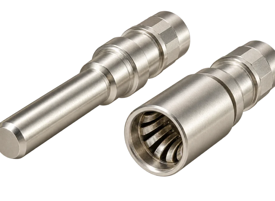
    전기차 급속충전 커넥터의 은색 수핀과 내부 다점 접촉 소켓

    전기차 급속충전 커넥터 접점: 고전류를 받는 핀과 소켓의 구조

    전기차 급속충전 커넥터 접점은 차량 인렛의 핀과 충전 플러그의 소켓이 만드는 고전류 인터페이스입니다. 눈에 잘 보이지 않는 접촉대, 도금과 케이블…
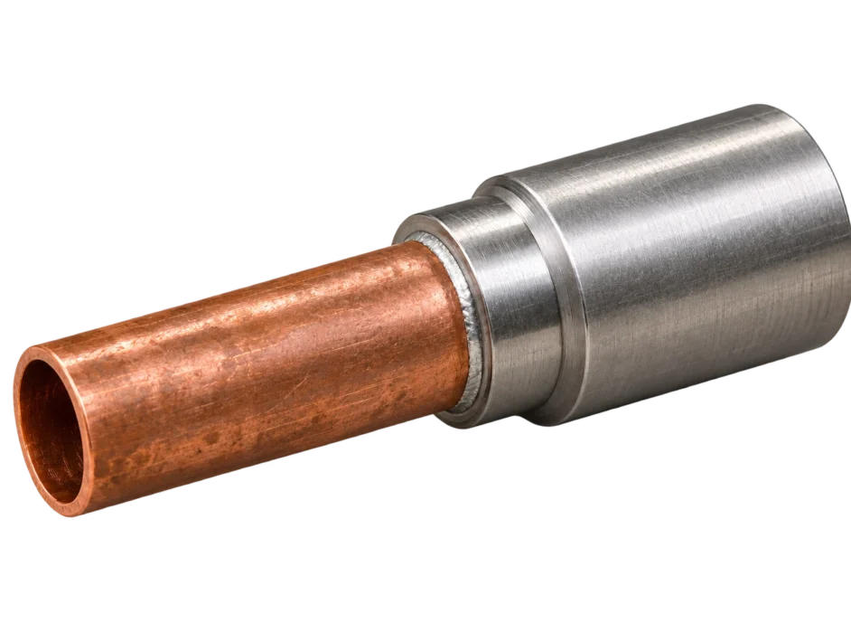
    구리관과 스테인리스 소켓이 은계 브레이징 접합층으로 연결된 조립 구조

    구리–스테인리스 이종 브레이징: 젖음·열간 간극·계면 내구성

    구리–스테인리스 이종 브레이징 설계에서는 젖음, 열간 간극, 용가재와 공정 관리를 함께 검토해야 합니다.
    LOUVER PANEL / 연결된 후드와 열린 통로

    판금 루버 성형: 개구 형상·금형·압력손실을 연결하는 설계

    루버는 판에 구멍을 많이 만드는 작업을 넘어, 절개한 재료를 원하는 방향으로 세워 공기의 통로와 패널의 구조를 함께 만드는 성형입니다.
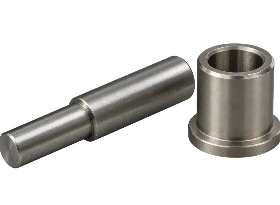
    PLATED INTERFACES / 단계 축과 플랜지 부시

    도금 공차 설계: 기능 치수·두께 분포·완성 검사

    정밀 부품의 표면처리는 재료의 기능을 바꾸면서 조립 공간도 바꿉니다. 외경은 커지고 내경은 작아지며, 마스킹 경계와 국부 성장까지 상대 부품의 움직임에…
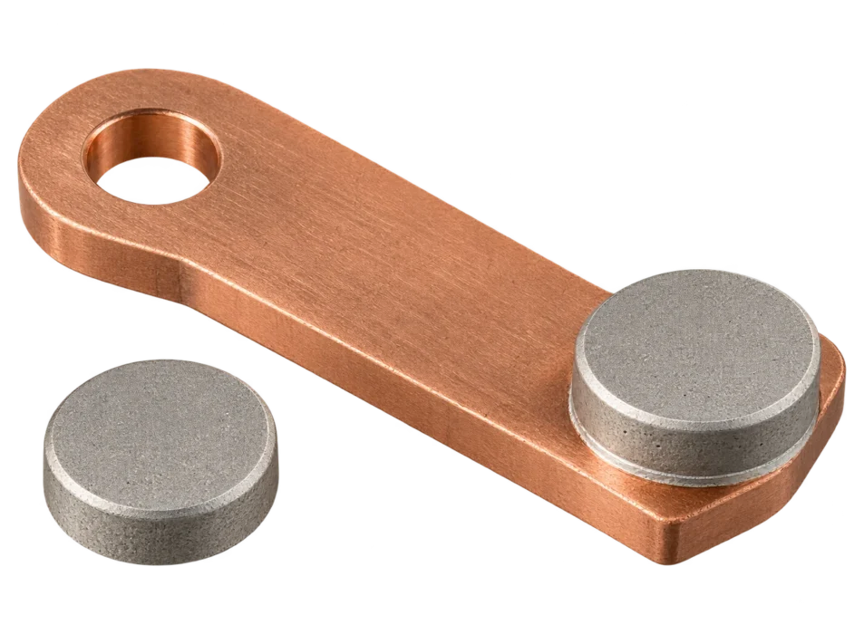
    AgW CONTACT / 구리 지지체에 접합된 복합 접점

    은·텅스텐 접점: 복합 조직·침투 제조·접합 품질의 설계

    두 상의 연결이 접점의 성능을 만듭니다.

    연결 준비 중입니다. 현재 전화 연결을 이용하실 수 있습니다.

    ID SOLUTECH
    LET’S TALK ENGINEERING

    무엇을
    도와드릴까요?

    아이디솔루텍의 제품과 제조 공정,
    기술자료에 대해 질문해 주세요.