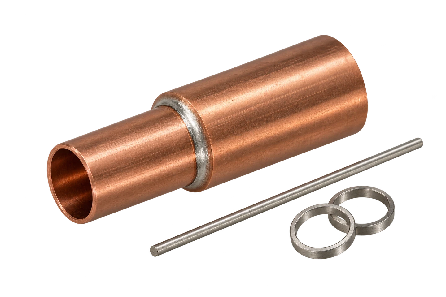
BRAZED JOINT / 동관·슬리브와 브레이징 프리폼

BRAZING FILLER SELECTION

간극을 읽고,
접합을 설계하다.

BCuP·BAg 용가재와 브레이징 품질의 연결

BRAZED JOINT / 동관·슬리브와 브레이징 프리폼

Select.
Heat.
Join.

BRAZING FILLER SELECTION

BRAZED JOINT / 동관·슬리브와 브레이징 프리폼

하나의 이음,
연결된 조건.

모재 적합성에서 고온 간극, 공급량과 검증까지 용가재 선정의 판단 기준을 정리합니다.

모재 · 간극 · 젖음 · 검증

Overview.

좋은 접합은 모재와 열이력을 함께 보는 데서 시작됩니다.

브레이징 용가재는 접합할 두 금속, 가열 중의 간극과 최종 사용 환경이 만나는 위치에서 선택해야 합니다. 은 함량이나 재료 가격만으로 등급을 정하면 젖음 부족, 취성 계면, 누설과 열변형의 원인을 놓치기 쉽습니다.

아이디솔루텍은 BCuP와 BAg를 서로 다른 재료군으로 구분하고, 도면에서 생산 검증까지 이어지는 선택 기준을 설명합니다. 아래 내용은 개별 제품의 설계·공정 검토를 위한 것으로, 특정 합금의 허용 온도나 강도를 모든 조립체에 적용하지 않습니다.

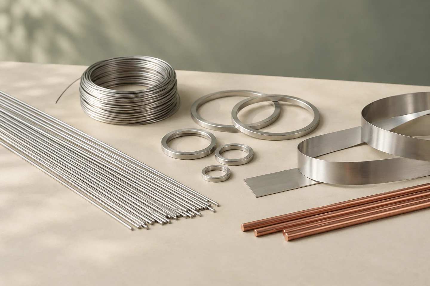
FILLER FORMS / 봉·와이어·링·박판 용가재

FILLER FORMS / 봉·와이어·링·박판 용가재

Structure.

접합 기능과 용가재 분류

01 / JOINT FUNCTION

용가재보다 먼저 접합부의 역할을 정의하다

밀봉·하중·열·전기 요구를 각각의 판정 기준으로 바꿉니다.

브레이징은 모재를 전체적으로 용융시키지 않고 그보다 낮은 온도에서 녹는 용가재를 이음부에 유입시켜 접합하는 공정입니다. 설계의 출발점은 어떤 금속봉이 잘 녹는가가 아니라 완성된 접합부가 무엇을 견뎌야 하는가입니다. 압력 유로의 누설, 반복 진동에 의한 피로, 열교환기의 열전달 또는 전류 경로의 발열은 서로 다른 평가 항목이며 한 가지 인장강도 수치로 모두 설명할 수 없습니다.

동일한 관경과 재료를 사용해도 겹침 길이, 접합 위치와 지지 구조가 바뀌면 하중 전달 방식이 달라집니다. 관을 당기는 힘만 있는지, 배관 자중에 의한 굽힘이나 체결 시 비틀림이 더해지는지 구분해야 합니다. 얇은 동관에 과도한 열을 넣어 모재가 연화된 경우에는 접합층보다 주변 관이 먼저 변형될 수 있으므로 접합재 자체의 물성만 높이는 접근으로 문제가 해결되지 않을 수 있습니다.

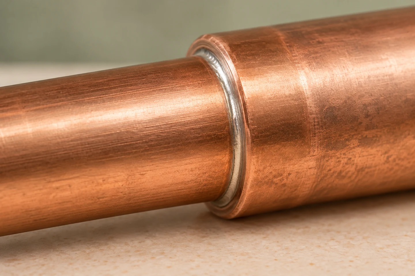
기술 검토표에는 모재 조합, 실제 접액 유체, 상시·일시 온도, 압력 변화, 진동과 허용 누설량을 각각 기입합니다. 외관용 필릿과 내부 충전 영역도 도면에서 구분해야 합니다. 표면에 매끈한 용가재 띠가 보이는 상태가 전체 겹침면의 결합을 증명하지는 않기 때문입니다. 초기 단계에서 시험 목적을 정해 두면 시제품을 분해하거나 절단할 위치도 생산 계획에 반영할 수 있습니다.

기밀 기능

연속 유로의 밀봉 · 누설 매체·감도·압력 지정

구조 기능

전단·굽힘·피로 하중 · 하중 방향과 지지 조건 확인

전달 기능

열·전류의 흐름 · 온도 상승과 접속 경로 평가

용가재보다 먼저 접합부의 역할을 정의하다 — 실무 판단 기준

검토 항목기술적 의미검증·관리 기준
기밀 기능연속 유로의 밀봉누설 매체·감도·압력 지정
구조 기능전단·굽힘·피로 하중하중 방향과 지지 조건 확인
전달 기능열·전류의 흐름온도 상승과 접속 경로 평가

기밀 기능

기술적 의미
연속 유로의 밀봉

검증·관리 기준
누설 매체·감도·압력 지정

구조 기능

기술적 의미
전단·굽힘·피로 하중

검증·관리 기준
하중 방향과 지지 조건 확인

전달 기능

기술적 의미
열·전류의 흐름

검증·관리 기준
온도 상승과 접속 경로 평가

02 / ALLOY FAMILIES

BCuP와 BAg를 등급 단위로 구분하다

같은 은 함량도 같은 모재 적합성과 유동성을 뜻하지 않습니다.

BCuP는 구리와 인을 기본으로 하며 등급에 따라 은 등이 들어가는 용가재군입니다. BAg는 은을 포함하는 여러 조성의 브레이징 용가재군으로 구리·아연·주석·니켈 등 다른 원소 조합이 달라집니다. 따라서 은이 들어 있다는 이유로 BCuP를 BAg와 같은 계열로 취급하거나 BAg의 주성분이 언제나 은이라고 단정하면 안 됩니다. 실제 선정에서는 분류 기호 뒤의 등급 번호와 공급 조성을 확인합니다.

등급을 정할 때 고상선, 액상선, 권장 브레이징 온도 범위를 구별합니다. 일부 조성은 비교적 좁은 범위에서 녹지만 다른 조성은 고체와 액체가 함께 있는 구간이 넓습니다. 두 재료군 중 하나는 항상 잘 흐르고 다른 하나는 항상 틈을 잘 메운다는 비교는 적절하지 않습니다. 유동 거동은 조성에 더해 모재 온도, 표면 상태, 간극, 공급 위치와 가열 속도에 영향을 받습니다.

구매 사양은 상품명만 기록하는 것보다 분류, 조성 요구, 공급 형태와 로트 식별을 함께 관리하는 편이 명확합니다. 대체품을 검토할 때도 은 함량 일치만으로 동등성을 인정하지 않고 용융 범위, 모재 반응, 플럭스 적합성과 완성품 시험을 비교합니다. 공급자 제품 설명에 있는 수치를 회사의 실제 생산 성능으로 옮기지 않고, 해당 조립체에서 확인된 범위를 승인 조건으로 남깁니다.

분류와 등급

조성군과 개별 합금 구분 · BCuP·BAg 뒤 번호 확인

온도 구간

고상선·액상선·작업온도 · 서로 다른 의미로 기록

공급 조건

형태·치수·로트 이력 · 구매 사양과 실물 대조

은 함량 증가가 모든 조건에서 강도와 젖음성을 높이는 단순한 법칙은 없습니다.

실무 적용

선정표의 한 행은 하나의 실제 등급으로 작성합니다. 후보의 장점뿐 아니라 사용하지 않을 모재와 환경도 함께 표시하면 유사한 상품명 사이의 오선정을 줄일 수 있습니다.

BCuP와 BAg를 등급 단위로 구분하다 — 실무 판단 기준

검토 항목기술적 의미검증·관리 기준
분류와 등급조성군과 개별 합금 구분BCuP·BAg 뒤 번호 확인
온도 구간고상선·액상선·작업온도서로 다른 의미로 기록
공급 조건형태·치수·로트 이력구매 사양과 실물 대조

분류와 등급

기술적 의미
조성군과 개별 합금 구분

검증·관리 기준
BCuP·BAg 뒤 번호 확인

온도 구간

기술적 의미
고상선·액상선·작업온도

검증·관리 기준
서로 다른 의미로 기록

공급 조건

기술적 의미
형태·치수·로트 이력

검증·관리 기준
구매 사양과 실물 대조

Materials.

모재 반응과 용융 거동

03 / BASE-METAL COMPATIBILITY

동·황동·강·스테인리스의 계면 반응을 확인하다

젖음과 계면의 건전성은 모재 조합에서 시작됩니다.

구리–구리 조합에서 일부 인 함유 용가재가 자체 플럭스 작용을 할 수 있다는 사실은 모든 구리 합금에 그대로 확장되지 않습니다. 황동과 청동에는 아연·주석·알루미늄 등 합금 원소와 그 산화물이 존재하므로 별도의 플럭스 또는 적합한 분위기 조건을 검토해야 합니다. 무산소동과 탈산동도 공급 상태와 열이력이 다르며, 도금층이나 표면 오염이 있으면 실제 용가재가 만나는 표면부터 다시 확인합니다.

철계와 니켈계 모재에 대한 인 함유 용가재의 사용은 취성 인화물 형성 가능성 때문에 주의가 필요합니다. 구리 부품이 포함된 조립체라도 상대 부품이 강이나 스테인리스라면 구리 배관용 처방을 그대로 사용하지 않습니다. 은이 포함된 인계 등급 역시 인의 영향을 없애지 못합니다. 표면에 잘 퍼진다는 외관만으로 계면의 연성이나 진동 내구성을 판정하지 않는 이유입니다.

스테인리스와 구리의 이종 접합에서는 산화피막 제거, 두 재료의 열전도 차이, 열팽창 차이와 냉각 후 잔류응력을 함께 검토합니다. 경우에 따라 적절한 BAg 등급이 후보가 되지만 모든 은계 용가재가 모든 환경에 맞는 것은 아닙니다. 모재를 변경하거나 도금 공정을 추가하면 기존 접합 조건의 적용 범위를 다시 검토하고 단면·기밀·기계 시험으로 필요한 재확인 범위를 정합니다.

구리–구리

인계 자체 플럭스 가능 · 등급·표면·가열조건 확인

황동·청동

합금 원소별 산화물 · 플럭스와 모재 침식 검토

철·니켈계

인화물 취성 가능성 · 인 함유 후보 적용 제한

실무 적용

재질표에 두 모재의 규격뿐 아니라 도금층, 산화막 제거 방법과 보관 이력을 추가합니다. 접합면의 실제 상태가 도면상의 재질명과 다르면 별도 시편으로 적용성을 검증합니다.

동·황동·강·스테인리스의 계면 반응을 확인하다 — 실무 판단 기준

검토 항목기술적 의미검증·관리 기준
구리–구리인계 자체 플럭스 가능등급·표면·가열조건 확인
황동·청동합금 원소별 산화물플럭스와 모재 침식 검토
철·니켈계인화물 취성 가능성인 함유 후보 적용 제한
이종 조합열전도·팽창의 차이양쪽 온도와 계면 검증

구리–구리

기술적 의미
인계 자체 플럭스 가능

검증·관리 기준
등급·표면·가열조건 확인

황동·청동

기술적 의미
합금 원소별 산화물

검증·관리 기준
플럭스와 모재 침식 검토

철·니켈계

기술적 의미
인화물 취성 가능성

검증·관리 기준
인 함유 후보 적용 제한

이종 조합

기술적 의미
열전도·팽창의 차이

검증·관리 기준
양쪽 온도와 계면 검증

JOINT DETAIL / 슬리브 입구의 연속 필릿

JOINT DETAIL / 슬리브 입구의 연속 필릿

04 / MELTING AND WETTING

용융 구간과 젖음 경로를 함께 설계하다

봉이 녹는 순간과 이음 전체가 충전되는 순간은 다릅니다.

고상선은 용융이 시작되는 온도이고 액상선은 평형 조건에서 합금이 완전히 액체가 되는 경계입니다. 실제 가열에서는 부품 간 온도차와 공급 속도 때문에 한 위치에서 용가재가 녹아도 이음의 먼 쪽은 유동에 필요한 상태에 도달하지 않을 수 있습니다. 따라서 불꽃에 닿은 봉 끝의 용융을 부품 전체의 온도 기준으로 삼지 않고, 이음부의 온도 분포와 유지시간을 확인해야 합니다.

젖음은 용가재와 고체 표면 사이의 상호작용이며, 잘 녹은 금속이 반드시 잘 젖는 것은 아닙니다. 유분, 산화물이나 소진된 플럭스가 남으면 방울처럼 뭉치거나 일부 경로만 따라 흘러갈 수 있습니다. 또한 가열을 계속해 흐름을 억지로 개선하면 모재 침식, 합금 성분 변화와 열변형이 늘어날 수 있으므로 젖음 불량은 먼저 표면과 온도 균일성의 문제로 분해해 진단합니다.

합금 원소 변경은 용융 구간뿐 아니라 응고 조직과 모재와의 반응에도 영향을 줍니다. 구리–인–은과 구리–인–주석 계열의 비교에서는 같은 저융점화 목적이라도 퍼짐성과 침식 거동이 같지 않을 수 있습니다. 이 원리를 근거로 대체 원소를 단순한 은 절감 수단으로 취급하지 않고, 실제 모재와 가열 방식에서 유동 길이·충전율·조직을 함께 비교하는 것이 합리적입니다.

용가재의 퍼짐 시험만으로 실제 겹침이음의 충전율을 확정하지 않습니다.

용융 구간과 젖음 경로를 함께 설계하다 — 실무 판단 기준

검토 항목기술적 의미검증·관리 기준
고상선첫 액상 발생부분 용융 상태 구분
액상선완전 액상 경계부품 온도와 별도 해석
젖음 상태표면과 용융금속의 상호작용산화물·오염·플럭스 확인
장시간 가열침식·변형 증가 가능성유지시간과 손상 관찰

고상선

기술적 의미
첫 액상 발생

검증·관리 기준
부분 용융 상태 구분

액상선

기술적 의미
완전 액상 경계

검증·관리 기준
부품 온도와 별도 해석

젖음 상태

기술적 의미
표면과 용융금속의 상호작용

검증·관리 기준
산화물·오염·플럭스 확인

장시간 가열

기술적 의미
침식·변형 증가 가능성

검증·관리 기준
유지시간과 손상 관찰

3D · 겹침 이음의 간극과 충전

STRUCTURE & INTERFACE
ID SOLUTECH / 01
인터랙티브 3D를 준비하고 있습니다.
가열 충전

색과 충전 경로는 공정 순서를 보여주며 실제 온도값은 아닙니다.

드래그·방향키: 회전 / + −: 확대·축소 / Home: 초기화겹침 이음의 간극과 충전

은 함량보다 먼저, 두 모재가 만나는 계면을 봅니다.

Precision.

간극과 표면 준비

05 / HOT CLEARANCE

상온 치수에서 가열 중 간극으로 이동하다

모세관 유동이 일어나는 온도에서 간극을 검토합니다.

모세관 작용을 이용하는 이음부에는 용가재가 연속적으로 통과할 경로가 필요합니다. 간극이 너무 좁으면 국부 접촉이나 잔류물 때문에 유로가 막힐 수 있고 너무 넓으면 모세관 구동과 접합층의 구속 상태가 달라집니다. 권장 간극은 용가재, 모재, 플럭스 사용 여부와 겹침 길이에 따라 달라지므로 특정 제품의 수치를 모든 브레이징 이음에 적용하지 않습니다.

관과 슬리브의 상온 끼워맞춤은 가열 중 그대로 유지되지 않습니다. 바깥 부품의 내경과 안쪽 부품의 외경이 각자의 열팽창률과 실제 온도에 따라 변합니다. 바깥 부품이 더 크게 팽창하면 간극이 열릴 수 있지만 반대 조건에서는 닫힐 수 있습니다. 두 부품이 같은 온도로 가열된다는 가정도 얇은 관과 두꺼운 피팅의 조합에서는 실제 온도 측정으로 확인해야 합니다.

간극 검토에는 평균값뿐 아니라 공차의 양끝, 원형도, 타원도, 조립 편심과 고정 지그의 구속을 포함합니다. 한쪽이 닿고 반대쪽만 넓은 상태는 명목 직경 차이로는 보이지 않습니다. 따라서 도면의 내·외경 측정과 실제 조립품의 단면 확인을 연결하고, 양산 초기에는 가능한 간극 범위의 대표 시편으로 유입과 접합 품질을 확인하는 편이 좋습니다.

명목 간극

설계 중심값 · 반경·직경 간극 구분

온도 간극

열팽창 후 실제 경로 · 양쪽 온도·팽창률 고려

국부 접촉

원형도·편심 영향 · 둘레 방향 최소 간극 확인

실무 적용

견적·도면 협의에서는 간극의 정의와 평가 온도를 문장으로 명시합니다. 측정하기 어려운 내부 위치는 조립 전 치수와 대표 단면을 조합해 확인 경로를 정합니다.

상온 치수에서 가열 중 간극으로 이동하다 — 실무 판단 기준

검토 항목기술적 의미검증·관리 기준
명목 간극설계 중심값반경·직경 간극 구분
온도 간극열팽창 후 실제 경로양쪽 온도·팽창률 고려
국부 접촉원형도·편심 영향둘레 방향 최소 간극 확인
공차 조합양산에서 가능한 극값대표 조합 시편 평가

명목 간극

기술적 의미
설계 중심값

검증·관리 기준
반경·직경 간극 구분

온도 간극

기술적 의미
열팽창 후 실제 경로

검증·관리 기준
양쪽 온도·팽창률 고려

국부 접촉

기술적 의미
원형도·편심 영향

검증·관리 기준
둘레 방향 최소 간극 확인

공차 조합

기술적 의미
양산에서 가능한 극값

검증·관리 기준
대표 조합 시편 평가

06 / SURFACE AND FLUX

세정·플럭스·분위기를 하나의 경로로 관리하다

산화물과 오염의 종류를 알아야 보호 방식이 결정됩니다.

브레이징 전처리는 용가재가 모재 표면에 직접 접근하도록 하는 과정입니다. 절삭유와 방청유를 제거하는 탈지, 산화막을 처리하는 기계적·화학적 준비, 세정 후 재오염을 막는 보관은 서로 다른 역할을 합니다. 플럭스에 유분 제거까지 맡기면 가열 중 분해물이나 기공의 원인이 남을 수 있으므로 투입 표면의 합격 조건을 별도로 정하고 깨끗한 장갑과 용기로 취급합니다.

플럭스는 모재의 산화물과 용가재의 온도 범위에 맞게 선택합니다. 가열 중 활성 상태를 유지해야 하고, 접합 후에는 필요한 위치에서 제거할 수 있어야 합니다. 과도한 도포량이 젖음성을 무조건 개선하지 않으며 좁은 틈에 잔류한 플럭스가 내부 충전을 방해하거나 사용 환경에서 부식 원인이 될 수 있습니다. 도포량·위치·건조 상태와 가열 지연을 일관되게 관리합니다.

진공이나 보호 분위기는 산화를 줄이기 위한 공정 조건이지만 모든 산화막을 자동으로 제거하지 않습니다. 분위기의 종류와 순도, 노점, 부품의 산화물 안정성 및 용가재의 휘발성 원소를 함께 검토해야 합니다. 토치용 용가재와 플럭스를 로 브레이징에 그대로 옮기지 않고 장비 조건과 공급자 적용 범위에 맞춰 다시 선정합니다. 내부 유로가 있는 제품은 분위기 교환과 잔류물 배출 가능성도 확인합니다.

탈지

유기 오염 제거 · 방법·세정 종료 기준

산화물 준비

젖음 가능한 표면 확보 · 합금별 표면 영향 확인

플럭스

산화물 반응·가열 보호 · 활성 범위와 제거성

실무 적용

세정 완료부터 조립·가열까지의 대기시간과 보관 방법을 관리합니다. 재작업품은 새 제품과 달리 남은 플럭스와 산화물을 가지고 있으므로 같은 투입 기준에 맞는지 먼저 판정합니다.

세정·플럭스·분위기를 하나의 경로로 관리하다 — 실무 판단 기준

검토 항목기술적 의미검증·관리 기준
탈지유기 오염 제거방법·세정 종료 기준
산화물 준비젖음 가능한 표면 확보합금별 표면 영향 확인
플럭스산화물 반응·가열 보호활성 범위와 제거성
분위기산소·수분·반응성 관리실측 조건과 재질 적합성

탈지

기술적 의미
유기 오염 제거

검증·관리 기준
방법·세정 종료 기준

산화물 준비

기술적 의미
젖음 가능한 표면 확보

검증·관리 기준
합금별 표면 영향 확인

플럭스

기술적 의미
산화물 반응·가열 보호

검증·관리 기준
활성 범위와 제거성

분위기

기술적 의미
산소·수분·반응성 관리

검증·관리 기준
실측 조건과 재질 적합성

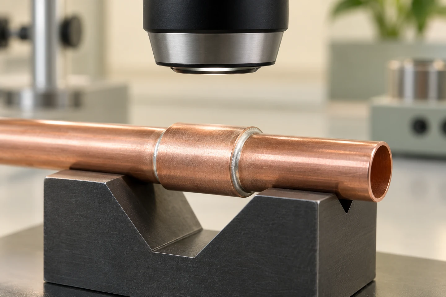
JOINT INSPECTION / 접합부 관찰과 검사 준비

JOINT INSPECTION / 접합부 관찰과 검사 준비

Motion.

공급 형상과 열팽창

07 / FILLER DELIVERY

와이어·링·박판의 배치를 충전 경로에 맞추다

필요 체적을 정하고 공기와 플럭스가 빠져나갈 길을 남깁니다.

봉이나 와이어는 가열 중 공급량을 조절하기 쉽지만 작업자의 공급 위치와 속도에 따라 편차가 생길 수 있습니다. 링과 기타 프리폼은 조립 단계에서 일정한 용가재 체적을 배치하기 유리하고, 박판은 평면 겹침부에 용가재를 분포시키는 후보가 됩니다. 어떤 형태도 자체적으로 충전 품질을 보장하지 않으므로 형상과 열원에 맞는 위치 고정, 오염 관리 및 공급량 검증이 필요합니다.

용가재 양은 겹침면의 이론적인 틈 체적, 목표 필릿과 공정 손실을 구분해 산정합니다. 입구에 많은 양을 쌓아 두면 깊은 곳까지 채워진다고 생각하기 쉽지만 내부의 공기·가스와 플럭스가 갇히면 표면만 두꺼워질 수 있습니다. 특히 막힌 끝을 가진 슬리브나 복잡한 분기에서는 유입 방향과 배출 방향을 도면에 함께 표시하고, 가열 순서로 배출이 차단되지 않는지 확인합니다.

프리폼의 단면적과 직경, 박판 두께, 와이어 절단 길이 편차는 모두 투입 질량에 영향을 줍니다. 반복 조립에서 링이 기울거나 한쪽으로 이동하면 둘레 전체에 균일하게 공급되지 않을 수 있습니다. 입고 치수 확인과 배치용 지그, 가열 전 검사 위치를 함께 정하고 공급 형태를 변경할 때는 기존 질량만 맞추는 대신 유동 경로와 작업 순서까지 재검토합니다.

와이어·봉

공급 위치와 속도 조절 · 작업 기준·투입량 확인

링 프리폼

둘레 방향 정량 공급 · 직경·단면·안착 관리

박판

평면 이음의 분포 공급 · 두께·면적·주름 확인

큰 외부 필릿은 내부 유효 접합 면적의 대체 지표가 아닙니다.

실무 적용

초기 시제품에서 투입 질량, 가열 후 외부 잔류량과 단면 충전 상태를 함께 기록합니다. 외관이 비슷한 두 조건의 내부 차이를 확인해야 공급량의 관리 범위를 정할 수 있습니다.

와이어·링·박판의 배치를 충전 경로에 맞추다 — 실무 판단 기준

검토 항목기술적 의미검증·관리 기준
와이어·봉공급 위치와 속도 조절작업 기준·투입량 확인
링 프리폼둘레 방향 정량 공급직경·단면·안착 관리
박판평면 이음의 분포 공급두께·면적·주름 확인
배출 경로공기·플럭스의 탈출막힌 끝과 가열 순서 검토

와이어·봉

기술적 의미
공급 위치와 속도 조절

검증·관리 기준
작업 기준·투입량 확인

링 프리폼

기술적 의미
둘레 방향 정량 공급

검증·관리 기준
직경·단면·안착 관리

박판

기술적 의미
평면 이음의 분포 공급

검증·관리 기준
두께·면적·주름 확인

배출 경로

기술적 의미
공기·플럭스의 탈출

검증·관리 기준
막힌 끝과 가열 순서 검토

3D · 필러 형상과 접합부 배치

PROCESS & VALIDATION
ID SOLUTECH / 02
인터랙티브 3D를 준비하고 있습니다.
박판 삽입

평면 겹침에서는 삽입재 두께와 평탄도를 함께 검토합니다.

드래그·방향키: 회전 / + −: 확대·축소 / Home: 초기화필러 형상과 접합부 배치
08 / THERMAL CLEARANCE MODEL

열팽창 계산으로 간극의 방향을 예측하다

간단한 계산은 설계 민감도를 보여 주며 최종 공정 검증을 대신하지 않습니다.

관–슬리브 조합의 반경 간극은 슬리브 내경에서 관 외경을 뺀 값을 절반으로 나누어 정의할 수 있습니다. 균일 온도와 자유 팽창을 가정하면 각 직경에 선팽창계수와 온도 상승을 적용해 가열 중의 변화를 근사할 수 있습니다. 이 계산의 목적은 간극이 열리는지 닫히는지, 어느 재료와 치수 공차에 민감한지 확인하는 데 있으며 특정 권장 간극을 자동으로 산출하는 도구는 아닙니다.

예를 들어 바깥 부품과 안쪽 부품의 팽창률이 크게 다르면 상온에서 양의 간극이 있어도 가열 후에는 국부 접촉이 생길 수 있습니다. 반대로 너무 느슨해져 용가재 층이 두꺼워지는 경우도 있습니다. 계산에는 공칭값 하나만 넣기보다 최소·최대 치수와 예상 온도차를 조합하고, 온도에 따라 달라지는 팽창계수는 필요한 정확도에 맞는 유효값 또는 온도 적분으로 처리합니다.

실제 부품에는 온도 구배, 원형도 오차, 지그 구속, 모재 연화와 국부 변형이 존재합니다. 따라서 음의 계산 간극을 정상적인 유동 상태로 간주하거나, 양의 값이 나왔다는 이유로 모든 둘레의 연속 간극이 확보됐다고 해석하지 않습니다. 측정 가능한 온도 위치를 정하고 대표 시편 단면과 비교해 모델의 범위를 확인한 뒤, 도면과 공정 조건의 변경 검토에 활용합니다.

gT ≈ {Dᵢ₀[1 + αs(Ts − T₀)] − Dₒ₀[1 + αt(Tt − T₀)]} / 2

기호·단위·적용 전제
gT는 가열 중 반경 간극(mm), Dᵢ₀는 기준온도 T₀의 슬리브 내경(mm), Dₒ₀는 관 외경(mm), αs·αt는 각각 슬리브·관의 유효 선팽창계수(K⁻¹), Ts·Tt는 각 부품 온도입니다. 온도차는 K 또는 °C로 일관되게 사용합니다. 축대칭·자유 팽창과 대표 온도를 가정한 1차 근사이며 비균일 가열, 구속과 소성변형은 포함하지 않습니다.

실무 적용

계산값과 실측값의 차이가 커지면 임의의 보정계수를 추가하기 전에 온도 측정 위치, 지그 접촉과 조립 편심을 확인합니다. 원인을 분리해야 다른 형상으로 전환할 때 같은 오차를 반복하지 않습니다.

열팽창 계산으로 간극의 방향을 예측하다 — 실무 판단 기준

검토 항목기술적 의미검증·관리 기준
Dᵢ₀·Dₒ₀초기 내경과 외경같은 기준온도·길이단위
α와 ΔT팽창률과 온도 상승두 부품을 별도로 입력
공차 극값가열 후 최소·최대 간극닫힘과 과대 간극 검토
모델 한계자유·균일 팽창 가정구속·구배는 별도 평가

Dᵢ₀·Dₒ₀

기술적 의미
초기 내경과 외경

검증·관리 기준
같은 기준온도·길이단위

α와 ΔT

기술적 의미
팽창률과 온도 상승

검증·관리 기준
두 부품을 별도로 입력

공차 극값

기술적 의미
가열 후 최소·최대 간극

검증·관리 기준
닫힘과 과대 간극 검토

모델 한계

기술적 의미
자유·균일 팽창 가정

검증·관리 기준
구속·구배는 별도 평가

용가재가 흐르는 간극은 가열 중에 결정됩니다.

Interface.

열이력과 사용 환경

09 / HEAT INPUT

토치·유도·로 가열의 열이력을 비교하다

같은 최고온도라도 가열 시간과 온도 분포가 다릅니다.

토치는 작업 위치와 불꽃 이동에 따라 국부 열입력을 조절할 수 있지만 작업 자세와 접근성의 영향을 받습니다. 유도 가열은 코일 형상, 결합 거리와 부품의 전기·자기 특성이 온도 분포를 좌우합니다. 로 가열은 많은 부품을 함께 처리할 수 있으나 장입량과 지그의 열용량, 분위기와 냉각 조건이 이력에 영향을 줍니다. 어떤 방식이 항상 더 좋은 접합을 만든다고 정하기보다 형상과 생산 조건에 맞춰 선택합니다.

가열 관리에는 설정 출력과 시간뿐 아니라 모재가 경험한 실제 온도를 포함해야 합니다. 용가재를 직접 과열해 표면에 녹여 붙이는 것과 모재가 적절한 온도에서 용가재를 받아들이는 것은 다릅니다. 두께가 다른 부품에서는 두꺼운 쪽의 가열 지연과 얇은 쪽의 과열이 동시에 생길 수 있으므로 측정 위치와 가열 순서를 정하고, 플럭스의 활성 시간이 필요한 충전 시간보다 충분한지 확인합니다.

냉각도 공정의 일부입니다. 응고 이전에 조립품이 움직이면 이음 형상이나 연속성이 손상될 수 있고, 급격한 냉각은 이종 재료 사이의 변형과 잔류응력에 영향을 줄 수 있습니다. 열민감 부품이나 경화 상태가 지정된 모재는 접합 뒤 물성이 유지되는지 별도로 검토합니다. 공정 변경 시 최고온도 하나만 비교하지 않고 가열·유지·냉각의 전체 경로와 최종 치수까지 검증합니다.

설비의 설정온도는 모든 접합면의 실제 온도와 같지 않습니다.

실무 적용

온도 확인용 대표 조립체는 실제 모재 두께와 지그 접촉을 재현합니다. 양산에서는 확인된 조건을 출력·시간·장입량 등의 관리 항목으로 연결하고 변경 시 재확인 기준을 적용합니다.

토치·유도·로 가열의 열이력을 비교하다 — 실무 판단 기준

검토 항목기술적 의미검증·관리 기준
토치국부·수동 열입력접근·불꽃 이동 표준화
유도코일과 부품의 결합거리·위치·출력 이력
로장입과 분위기의 영향대표품 온도·냉각 확인
냉각응고와 변형 관리고정 해제 시점 정의

토치

기술적 의미
국부·수동 열입력

검증·관리 기준
접근·불꽃 이동 표준화

유도

기술적 의미
코일과 부품의 결합

검증·관리 기준
거리·위치·출력 이력

로

기술적 의미
장입과 분위기의 영향

검증·관리 기준
대표품 온도·냉각 확인

냉각

기술적 의미
응고와 변형 관리

검증·관리 기준
고정 해제 시점 정의

10 / SERVICE AND COST

사용 환경과 총공정 비용으로 후보를 좁히다

재료 단가와 사용 중 신뢰성을 같은 선정표에서 검토합니다.

브레이징 접합부의 내식성과 내열성은 용가재 이름만으로 결정되지 않습니다. 접액 유체, 황 함유 환경, 세정 약품, 습도와 틈새의 상태를 모재와 함께 검토해야 합니다. 특정 인계 합금은 황 함유 물질이나 가압 증기 조건에서 부식에 취약할 수 있으므로 통상적인 구리 배관 사용 경험을 모든 유체 시스템에 확장하지 않습니다. 시험 환경은 실제 서비스의 중요한 화학종과 온도를 대표해야 합니다.

반복 진동과 열사이클에서는 접합층의 연성뿐 아니라 겹침 끝단의 응력 집중, 지지 간격과 모재의 열영향이 중요합니다. 은 함량이 높은 후보로 바꾸는 것만으로 구조상의 취약점이 사라지지 않습니다. 유체 압력 변화와 기계적 진동이 함께 존재하면 각각의 단독 시험뿐 아니라 실제 조합에서 나타나는 하중 경로를 검토하고, 필요한 반복 조건과 파손 위치의 기록 방법을 정합니다.

비용 비교는 용가재의 질량당 가격에 실제 투입량, 세정·플럭스 제거, 가열 시간, 지그와 검사 비용을 더해 수행합니다. 프리폼은 초기 제작비가 있어도 투입량과 작업 편차를 줄일 수 있고, 반대로 적은 수량의 복잡한 제품에는 유연한 공급 형태가 유리할 수 있습니다. 단가가 낮은 후보에서 재작업이나 누설 검사 불합격이 늘어난다면 총비용은 높아질 수 있으므로 동일한 합격 기준으로 비교합니다.

환경 적합성

유체·온도·틈새 반응 · 접액 조건과 부식 시험

반복 하중

피로·열사이클 영향 · 파손 위치와 변형 확인

투입 비용

질량·가열·세정 · 실제 소비량 기준 비교

실무 적용

후보별로 필수 요구 충족 여부를 먼저 판단한 뒤 합격 가능한 후보끼리 비용을 비교합니다. 요구를 만족하지 못한 재료를 낮은 가격 때문에 같은 순위표에 넣지 않도록 선정 절차를 구분합니다.

사용 환경과 총공정 비용으로 후보를 좁히다 — 실무 판단 기준

검토 항목기술적 의미검증·관리 기준
환경 적합성유체·온도·틈새 반응접액 조건과 부식 시험
반복 하중피로·열사이클 영향파손 위치와 변형 확인
투입 비용질량·가열·세정실제 소비량 기준 비교
품질 비용불합격·재작업·검사동일 합격 기준 유지

환경 적합성

기술적 의미
유체·온도·틈새 반응

검증·관리 기준
접액 조건과 부식 시험

반복 하중

기술적 의미
피로·열사이클 영향

검증·관리 기준
파손 위치와 변형 확인

투입 비용

기술적 의미
질량·가열·세정

검증·관리 기준
실제 소비량 기준 비교

품질 비용

기술적 의미
불합격·재작업·검사

검증·관리 기준
동일 합격 기준 유지

Validation.

검증과 생산 승인

11 / VERIFICATION

외관·누설·단면·기계 시험의 역할을 나누다

각 시험이 확인하는 결함과 놓치는 영역을 정의합니다.

외관 검사는 필릿의 연속성, 과도한 용가재, 표면 균열과 열변색을 빠르게 확인하는 데 유용합니다. 그러나 내부 겹침면의 미접합, 플럭스 잔류와 기공을 모두 보여 주지는 않습니다. 누설 시험 역시 정해진 압력차와 매체, 감도에서 관통 경로를 찾는 평가이므로 누설이 없다는 결과만으로 충분한 전단 면적이나 피로 수명을 증명했다고 해석하지 않습니다.

단면 검사는 충전의 분포, 계면 반응층, 국부 침식과 잔류물을 직접 관찰할 수 있지만 절단 위치에 따라 결과가 달라집니다. 입구에서 좋은 단면 하나를 얻었다고 전체 둘레와 길이가 건전하다고 단정하지 않고, 불량이 발생하기 쉬운 끝단·온도 저하 위치·가스 포획 부위를 포함해 계획합니다. 절단과 연마 과정이 만든 손상을 실제 접합 결함과 구분하는 준비 절차도 필요합니다.

기계 시험은 실제 하중 방향을 대표하는 형상과 고정 방식으로 설계합니다. 겹침 길이가 다른 시편의 최대하중을 그대로 재료 강도처럼 비교하지 않고 유효 면적, 모재 파손 여부와 시험 속도를 함께 기록합니다. 양산 검사 항목은 개발 중 확인한 결함 모드와 연결하고, 초기 검증·주기 확인·출하 검사의 역할을 구분해 필요한 증거가 빠지지 않도록 구성합니다.

외관

표면 이상 탐지 · 조명·배율·허용상태 정의

누설

관통 결함의 검출 · 매체·압력·감도 기록

단면

충전·계면·침식 관찰 · 절단 위치와 준비 조건

서로 다른 시험은 서로 다른 질문에 답하며 결과를 한 가지 합격 표시로 대체하지 않습니다.

실무 적용

시험 성적에는 합격 여부와 함께 시험편 식별, 접합 조건, 평가 위치와 실제 측정값을 남깁니다. 이상이 반복될 때는 결과 숫자만 비교하지 않고 파손면과 단면 위치를 공정 이력에 연결합니다.

외관·누설·단면·기계 시험의 역할을 나누다 — 실무 판단 기준

검토 항목기술적 의미검증·관리 기준
외관표면 이상 탐지조명·배율·허용상태 정의
누설관통 결함의 검출매체·압력·감도 기록
단면충전·계면·침식 관찰절단 위치와 준비 조건
기계 평가하중 전달 성능형상·고정·파손 모드

외관

기술적 의미
표면 이상 탐지

검증·관리 기준
조명·배율·허용상태 정의

누설

기술적 의미
관통 결함의 검출

검증·관리 기준
매체·압력·감도 기록

단면

기술적 의미
충전·계면·침식 관찰

검증·관리 기준
절단 위치와 준비 조건

기계 평가

기술적 의미
하중 전달 성능

검증·관리 기준
형상·고정·파손 모드

12 / PRODUCTION RELEASE

선정 근거를 작업 조건과 변경 관리에 연결하다

최종 등급·형상·가열·검사를 한 승인 묶음으로 관리합니다.

양산 승인에는 용가재 등급만 적는 것으로 충분하지 않습니다. 모재와 표면 상태, 조립 간극, 프리폼 또는 공급량, 플럭스·분위기, 가열·냉각 조건과 검사 기준이 함께 연결되어야 합니다. 하나의 조건을 변경했을 때 영향받는 항목을 추적할 수 있도록 도면 개정, 소재 로트와 작업 기록의 식별 체계를 맞추면 문제 발생 시 확인 범위를 좁힐 수 있습니다.

생산 중 불량이 나타나면 먼저 발생 위치와 시점을 분류합니다. 입구의 미젖음은 표면 준비나 가열 문제와 연결될 수 있고, 내부의 미충전은 간극·배출·열분포를 함께 의심해야 합니다. 반복되는 특정 방향의 결함은 조립 편심이나 열원 위치, 지그 접촉의 영향을 보여 줄 수 있습니다. 원인을 하나로 단정하기보다 조건별 관찰 결과를 비교하고 수정 후에는 원래의 기능 시험으로 효과를 확인합니다.

아이디솔루텍에 브레이징 관련 검토를 요청할 때는 두 모재의 규격과 공급 상태, 접합부 도면, 유체·온도·하중, 예상 수량과 검사·문서 요구를 함께 전달하면 논의가 구체적이 됩니다. 보유 장비나 특정 공정 능력에 대한 가정 없이 실제 요구와 가능한 검증 경로를 맞추는 것이 우선입니다. 초기 시편부터 승인 조건을 기록하면 대체 용가재나 설계 변경도 같은 판단 체계에서 평가할 수 있습니다.

승인 구성

재질·간극·열이력 연결 · 관리본과 로트 식별

변경 심사

대체재·지그·가열 변화 · 영향 범위와 재확인

이상 분석

위치·시점·파손 모드 · 공정 조건별 비교

실무 적용

최초 승인품과 변경품의 비교 항목을 미리 정하고 관리 가능한 기록으로 남깁니다. 수율 개선 결과는 합격 기준이 동일할 때 해석하며, 검사를 줄이려면 결함 검출 근거부터 확인합니다.

선정 근거를 작업 조건과 변경 관리에 연결하다 — 실무 판단 기준

검토 항목기술적 의미검증·관리 기준
승인 구성재질·간극·열이력 연결관리본과 로트 식별
변경 심사대체재·지그·가열 변화영향 범위와 재확인
이상 분석위치·시점·파손 모드공정 조건별 비교
문의 입력도면·환경·검사 요구대표 시편과 제출 범위

승인 구성

기술적 의미
재질·간극·열이력 연결

검증·관리 기준
관리본과 로트 식별

변경 심사

기술적 의미
대체재·지그·가열 변화

검증·관리 기준
영향 범위와 재확인

이상 분석

기술적 의미
위치·시점·파손 모드

검증·관리 기준
공정 조건별 비교

문의 입력

기술적 의미
도면·환경·검사 요구

검증·관리 기준
대표 시편과 제출 범위

필릿의 외관과 내부 충전은 함께 확인해야 합니다.

Start a
Project.

두 모재의 규격과 공급 상태, 접합 도면, 유체·온도·하중, 예상 수량과 검사 요구를 보내주세요. 간극·용가재·열이력과 검증 경로를 함께 검토합니다.

Provide substrate specifications, supply condition, drawing, fluid, temperature, loads, quantity and inspection requirements for a connected process review.

개발 상담 · Contact

기술 협의 · Engineering Consultation
도면과 사양을 기준으로 소재·가공·표면처리,
주요 품질 항목과 공급 조건을 함께 검토합니다.


We review drawings and specifications to define materials, manufacturing methods, surface finishes, key quality requirements, and supply conditions.

개발 의뢰하기 · Development Inquiry

    도면 및 기술자료
    Drawings & Technical Documents

    도면 번호와 개정 이력이 표시된 2D·3D 도면을 첨부해 주세요.
    사양서와 검사 기준도 함께 전달할 수 있습니다.
    Attach your 2D or 3D drawings with their drawing numbers and revisions.
    Include specifications and inspection criteria as needed.

    파일을 이곳에 놓아주세요Drag & drop your files here

    선택된 파일 없음 / No files attached

    최대 5개 · 파일당 5MB · 총 15MB / Up to 5 files · 5MB each · 15MB total
    PDF · DWG · DXF · STEP/STP · IGS/IGES · JPG · PNG · ZIP

    * 필수 입력 / Required fields

    BRAZING FILLER SELECTION

    BRAZED JOINT / 동관·슬리브와 브레이징 프리폼

    One Joint.
    Connected Conditions.

    Connect compatibility, hot clearance, charge and verification to filler selection.

    SUBSTRATE · GAP · WETTING · VERIFY

    ENGLISH EDITION

    Read the Gap.
    Design the Joint.

    Connecting BCuP and BAg fillers to brazing quality

    Reliable joining begins with substrates and thermal history.

    Choose a brazing filler where the two base metals, hot joint clearance and service environment intersect. Silver content and purchase price alone do not reveal poor wetting, brittle interfaces, leakage or thermal distortion.

    ID SOLUTECH explains BCuP and BAg as distinct filler families and connects drawing requirements to process verification. Product-specific design and qualification determine allowable temperatures and joint performance.

    FILLER FORMS / 봉·와이어·링·박판 용가재

    FILLER FORMS / Rod, wire, rings and foil

    Structure.

    Joint duty and filler classification

    01 / JOINT FUNCTION

    Define the Joint Function Before the Filler

    Translate sealing, load, thermal and electrical duties into separate criteria.

    Brazing joins base metals with a lower-melting filler while the base components remain substantially solid. Start with what the completed assembly must withstand. Leakage, vibration fatigue, heat transfer and electrical heating are distinct duties; a single tensile value does not establish all of them.

    Overlap, joint location and support change load transfer even with identical tube sizes and alloys. Separate axial force from bending and assembly torque. Excessive heating can soften a thin copper tube, allowing surrounding material to deform before the joint itself fails.

    Record the metal pair, actual fluid, steady and transient temperature, pressure changes, vibration and leakage criterion. Distinguish the visible fillet from the internal bonded area. Defining test objectives early also determines where representative assemblies should be sectioned.

    Sealing

    Continuous fluid boundary. Specify medium, sensitivity and pressure

    Structural duty

    Shear, bending and fatigue. Review load direction and supports

    Transfer duty

    Heat and current paths. Evaluate temperature rise and connections

    Define the Joint Function Before the Filler — Review Criteria

    Review itemEngineering significanceVerification or control
    SealingContinuous fluid boundarySpecify medium, sensitivity and pressure
    Structural dutyShear, bending and fatigueReview load direction and supports
    Transfer dutyHeat and current pathsEvaluate temperature rise and connections

    Sealing

    Engineering significance
    Continuous fluid boundary

    Verification or control
    Specify medium, sensitivity and pressure

    Structural duty

    Engineering significance
    Shear, bending and fatigue

    Verification or control
    Review load direction and supports

    Transfer duty

    Engineering significance
    Heat and current paths

    Verification or control
    Evaluate temperature rise and connections

    02 / ALLOY FAMILIES

    Distinguish BCuP and BAg by Grade

    Equal silver content does not imply equal compatibility or flow.

    BCuP identifies copper-phosphorus fillers, with silver in some grades. BAg covers silver-bearing fillers with varying copper, zinc, tin, nickel and other additions. Silver in a BCuP alloy does not make it a BAg grade, and silver is not necessarily the majority element in every BAg composition.

    Separate solidus, liquidus and the recommended brazing range. Some compositions melt over a narrow interval while others retain a broad solid-liquid region. Family names alone cannot rank flow or gap-filling behavior; temperature, surface preparation, clearance and feed location also matter.

    Specify classification, chemistry requirements, form and lot identity rather than trade name alone. Substitute evaluation should compare melting behavior, interaction, flux compatibility and assembly tests. Supplier data become input to qualification, not automatic evidence of in-house capability.

    Class and grade

    Family versus individual composition. Check the complete designation

    Temperature interval

    Solidus, liquidus and process range. Record each separately

    Supply condition

    Form, dimensions and traceability. Compare specification and receipt

    Increasing silver content is not a universal law for greater strength or wetting.

    Application review

    Use one row per actual grade and record excluded substrates and environments as well as benefits.

    Distinguish BCuP and BAg by Grade — Review Criteria

    Review itemEngineering significanceVerification or control
    Class and gradeFamily versus individual compositionCheck the complete designation
    Temperature intervalSolidus, liquidus and process rangeRecord each separately
    Supply conditionForm, dimensions and traceabilityCompare specification and receipt

    Class and grade

    Engineering significance
    Family versus individual composition

    Verification or control
    Check the complete designation

    Temperature interval

    Engineering significance
    Solidus, liquidus and process range

    Verification or control
    Record each separately

    Supply condition

    Engineering significance
    Form, dimensions and traceability

    Verification or control
    Compare specification and receipt

    Materials.

    Compatibility and melting behavior

    03 / BASE-METAL COMPATIBILITY

    Check Interface Reactions for Each Metal Pair

    Wetting and interface integrity begin with the base-metal pair.

    Self-fluxing behavior of certain phosphorus-bearing fillers on copper does not apply automatically to every copper alloy. Brass and bronze introduce additional oxide systems. Coatings and contamination may also change the surface actually contacted by the filler.

    Phosphorus-bearing fillers require exclusion or specific review for ferrous and nickel substrates because brittle phosphides can form. A copper component in a mixed assembly does not justify a copper-piping recipe. Silver additions do not cancel phosphorus-related interface risks.

    For stainless-to-copper joints, consider oxide removal, unequal heat conduction, differential expansion and cooling stresses. An appropriate BAg grade may be a candidate, but suitability remains grade and environment specific. Material or coating changes trigger a defined requalification review.

    Copper to copper

    Possible self-fluxing action. Verify grade, surface and heating

    Brass and bronze

    Different oxide systems. Review flux and erosion

    Ferrous and nickel

    Brittle phosphide risk. Restrict phosphorus-bearing candidates

    Application review

    Add coatings, oxide removal and storage history to the two substrate specifications. Verify surfaces that differ from the nominal drawing description.

    Check Interface Reactions for Each Metal Pair — Review Criteria

    Review itemEngineering significanceVerification or control
    Copper to copperPossible self-fluxing actionVerify grade, surface and heating
    Brass and bronzeDifferent oxide systemsReview flux and erosion
    Ferrous and nickelBrittle phosphide riskRestrict phosphorus-bearing candidates
    Dissimilar pairThermal conduction and expansionVerify temperatures and interfaces

    Copper to copper

    Engineering significance
    Possible self-fluxing action

    Verification or control
    Verify grade, surface and heating

    Brass and bronze

    Engineering significance
    Different oxide systems

    Verification or control
    Review flux and erosion

    Ferrous and nickel

    Engineering significance
    Brittle phosphide risk

    Verification or control
    Restrict phosphorus-bearing candidates

    Dissimilar pair

    Engineering significance
    Thermal conduction and expansion

    Verification or control
    Verify temperatures and interfaces

    JOINT DETAIL / 슬리브 입구의 연속 필릿

    JOINT DETAIL / Continuous sleeve-entry fillet

    04 / MELTING AND WETTING

    Design the Melting Interval and Wetting Path

    Filler melting and complete joint filling are different events.

    Solidus marks melting onset and liquidus bounds the fully liquid equilibrium region. A rod melting at one location does not mean the far side of an assembly is hot enough for flow. Review joint temperature distribution and hold time.

    Melting does not guarantee wetting. Oil, oxides and exhausted flux can produce beading or preferential flow. Prolonged heating may add erosion and distortion instead of correcting preparation or temperature nonuniformity.

    Composition changes affect solidification and substrate interaction as well as melting. Different additions to copper-phosphorus systems can produce different spreading and erosion behavior. Compare flow distance, filling and structure on the actual substrate before approving an alloy substitution.

    A spreading test alone does not establish lap-joint filling.

    Design the Melting Interval and Wetting Path — Review Criteria

    Review itemEngineering significanceVerification or control
    SolidusFirst liquid formationDistinguish partial melting
    LiquidusFully liquid boundarySeparate from actual part temperature
    WettingSurface–liquid interactionCheck oxide, contamination and flux
    Long heatingPotential erosion and distortionReview hold time and damage

    Solidus

    Engineering significance
    First liquid formation

    Verification or control
    Distinguish partial melting

    Liquidus

    Engineering significance
    Fully liquid boundary

    Verification or control
    Separate from actual part temperature

    Wetting

    Engineering significance
    Surface–liquid interaction

    Verification or control
    Check oxide, contamination and flux

    Long heating

    Engineering significance
    Potential erosion and distortion

    Verification or control
    Review hold time and damage

    3D · Lap Joint Clearance and Filling

    STRUCTURE & INTERFACE
    ID SOLUTECH / 01
    Preparing interactive 3D.
    Heated filling

    Color and filling illustrate sequence rather than measured temperature.

    Drag / arrow keys: rotate · + −: zoom · Home: resetLap Joint Clearance and Filling

    Examine the interface before ranking silver content.

    Precision.

    Clearance and surface preparation

    05 / HOT CLEARANCE

    Translate Room-Temperature Dimensions to Hot Clearance

    Review clearance at the temperature where capillary flow occurs.

    Capillary joints need continuous flow paths. Too little clearance can close locally or trap residues; excessive clearance changes capillary driving and constraint of the filler layer. Recommended gaps depend on alloy, substrate, flux and overlap.

    Tube and sleeve dimensions change independently with expansion coefficient and actual temperature. The gap can open or close during heating. Equal temperature is itself an assumption that should be checked for a thin tube inside a thick fitting.

    Include tolerance extremes, roundness, ovality, eccentric assembly and fixture constraint. Nominal diameter difference cannot reveal contact on one side and a wide gap on the other. Connect dimensional inspection to sections of representative assembled joints.

    Nominal gap

    Design center. Distinguish radial and diametral

    Hot gap

    Expanded flow path. Consider both temperatures and coefficients

    Local contact

    Roundness and eccentricity. Check circumferential minimum

    Application review

    State clearance definition and evaluation temperature in drawing review. Combine preassembly dimensions and representative sections for inaccessible regions.

    Translate Room-Temperature Dimensions to Hot Clearance — Review Criteria

    Review itemEngineering significanceVerification or control
    Nominal gapDesign centerDistinguish radial and diametral
    Hot gapExpanded flow pathConsider both temperatures and coefficients
    Local contactRoundness and eccentricityCheck circumferential minimum
    Tolerance stackProduction extremesEvaluate representative combinations

    Nominal gap

    Engineering significance
    Design center

    Verification or control
    Distinguish radial and diametral

    Hot gap

    Engineering significance
    Expanded flow path

    Verification or control
    Consider both temperatures and coefficients

    Local contact

    Engineering significance
    Roundness and eccentricity

    Verification or control
    Check circumferential minimum

    Tolerance stack

    Engineering significance
    Production extremes

    Verification or control
    Evaluate representative combinations

    06 / SURFACE AND FLUX

    Connect Cleaning, Flux and Atmosphere

    Identify contamination and oxides before selecting protection.

    Preparation gives the filler access to the substrate. Degreasing, oxide removal and protected storage serve different purposes. Flux should not be relied on to remove oils that may leave decomposition products during heating.

    Match flux to the oxide system and thermal range. It must remain active and be removable where required. Excess flux is not automatically better; define amount, placement, condition and delay before heating.

    Vacuum or protective gas does not automatically remove every oxide. Gas chemistry, purity, dew point, oxide stability and volatile alloying elements matter. Reassess a torch-brazing consumable before transferring it to furnace service.

    Degreasing

    Organic contamination removal. Define method and endpoint

    Oxide preparation

    Wetable substrate access. Check alloy-specific effects

    Flux

    Oxide reaction and protection. Match active range and removal

    Application review

    Control delay and storage between cleaning and heating. Rework parts need assessment of existing flux and oxides before re-entry.

    Connect Cleaning, Flux and Atmosphere — Review Criteria

    Review itemEngineering significanceVerification or control
    DegreasingOrganic contamination removalDefine method and endpoint
    Oxide preparationWetable substrate accessCheck alloy-specific effects
    FluxOxide reaction and protectionMatch active range and removal
    AtmosphereOxygen, moisture and reactivityVerify actual conditions and compatibility

    Degreasing

    Engineering significance
    Organic contamination removal

    Verification or control
    Define method and endpoint

    Oxide preparation

    Engineering significance
    Wetable substrate access

    Verification or control
    Check alloy-specific effects

    Flux

    Engineering significance
    Oxide reaction and protection

    Verification or control
    Match active range and removal

    Atmosphere

    Engineering significance
    Oxygen, moisture and reactivity

    Verification or control
    Verify actual conditions and compatibility

    JOINT INSPECTION / 접합부 관찰과 검사 준비

    JOINT INSPECTION / Joint observation and inspection preparation

    Motion.

    Filler delivery and thermal expansion

    07 / FILLER DELIVERY

    Match Wire, Rings and Foil to the Flow Path

    Define filler volume while preserving gas and flux escape paths.

    Rod and wire allow adjustable feed but introduce operator-dependent position and rate. Rings and other preforms establish a repeatable charge; foil can distribute filler in planar laps. Each form still requires location, cleanliness and charge verification.

    Separate theoretical gap volume, desired fillet and process losses. A large charge at the entrance can leave internal gas or flux trapped. Mark entry and escape directions for blind sleeves and branched geometry and check how heating affects them.

    Ring section, diameter, foil thickness and wire cut length all affect charge mass. Tilted or displaced preforms create uneven supply. A form change therefore requires review of flow and assembly sequence, not simply equal nominal mass.

    Wire and rod

    Adjustable feed location and rate. Control method and charge

    Ring preform

    Metered circumferential supply. Check size, section and seating

    Foil

    Distributed planar supply. Check thickness, area and folds

    A large external fillet is not a substitute for internal bonded area.

    Application review

    Record charge mass, external residue and sectioned filling during development to distinguish conditions with similar appearance.

    Match Wire, Rings and Foil to the Flow Path — Review Criteria

    Review itemEngineering significanceVerification or control
    Wire and rodAdjustable feed location and rateControl method and charge
    Ring preformMetered circumferential supplyCheck size, section and seating
    FoilDistributed planar supplyCheck thickness, area and folds
    Escape routeGas and flux exitReview blind ends and heat sequence

    Wire and rod

    Engineering significance
    Adjustable feed location and rate

    Verification or control
    Control method and charge

    Ring preform

    Engineering significance
    Metered circumferential supply

    Verification or control
    Check size, section and seating

    Foil

    Engineering significance
    Distributed planar supply

    Verification or control
    Check thickness, area and folds

    Escape route

    Engineering significance
    Gas and flux exit

    Verification or control
    Review blind ends and heat sequence

    3D · Filler Form and Joint Placement

    PROCESS & VALIDATION
    ID SOLUTECH / 02
    Preparing interactive 3D.
    Foil insert

    For planar laps, review foil thickness and substrate flatness.

    Drag / arrow keys: rotate · + −: zoom · Home: resetFiller Form and Joint Placement
    08 / THERMAL CLEARANCE MODEL

    Predict Clearance Change with Thermal Expansion

    A simple model reveals sensitivity and supports process verification.

    For a sleeve and tube, radial clearance is half the sleeve bore minus tube diameter. Uniform temperature and free expansion permit a first-order dimensional estimate. The model reveals direction and sensitivity; it does not choose the required brazing gap.

    Combine minimum and maximum dimensions with plausible temperature differences. A positive room-temperature gap may close or become excessive. Use suitable effective expansion coefficients or temperature integration when accuracy requires it.

    Thermal gradients, ovality, fixture restraint and local deformation limit the model. Negative clearance is not a valid flow condition, and a positive result does not prove clearance everywhere. Compare instrumented temperatures and representative sections before using the model for change review.

    gT ≈ {Dᵢ₀[1 + αs(Ts − T₀)] − Dₒ₀[1 + αt(Tt − T₀)]} / 2

    Symbols, units and assumptions
    gT is hot radial clearance (mm); Dᵢ₀ is sleeve bore and Dₒ₀ tube outside diameter at reference T₀ (mm). αs and αt are effective linear expansion coefficients (K⁻¹); Ts and Tt are component temperatures. Use consistent K or °C differences. This first-order axisymmetric free-expansion estimate excludes gradients, restraint and plastic deformation.

    Application review

    Investigate thermocouple location, fixture contact and eccentricity before introducing empirical correction factors.

    Predict Clearance Change with Thermal Expansion — Review Criteria

    Review itemEngineering significanceVerification or control
    Dᵢ₀ and Dₒ₀Initial bore and outside diameterCommon reference temperature and units
    α and ΔTExpansion and temperature riseEnter each component separately
    Tolerance extremesMinimum and maximum hot gapReview closure and excess opening
    Model limitsFree, uniform expansionAssess restraint and gradients separately

    Dᵢ₀ and Dₒ₀

    Engineering significance
    Initial bore and outside diameter

    Verification or control
    Common reference temperature and units

    α and ΔT

    Engineering significance
    Expansion and temperature rise

    Verification or control
    Enter each component separately

    Tolerance extremes

    Engineering significance
    Minimum and maximum hot gap

    Verification or control
    Review closure and excess opening

    Model limits

    Engineering significance
    Free, uniform expansion

    Verification or control
    Assess restraint and gradients separately

    The flow gap is determined during heating.

    Interface.

    Thermal cycle and service exposure

    09 / HEAT INPUT

    Compare Torch, Induction and Furnace Thermal Histories

    Equal peak temperature does not imply equal time or distribution.

    Torch heating depends on flame movement and access; induction depends on coil coupling and material properties; furnace heating depends on loading, fixture mass, atmosphere and cooling. Select the method for the geometry and production conditions.

    Control actual substrate temperature as well as power and time. Melting filler directly onto a cold substrate differs from feeding a properly heated joint. Unequal wall thickness can produce simultaneous underheating and overheating.

    Cooling is part of the process. Movement before solidification can disrupt the joint, while rapid cooling affects distortion and stress. Compare the full heating, hold and cooling route and final properties when changing equipment or settings.

    Equipment setpoint is not the actual temperature of every joint surface.

    Application review

    Instrument representative geometry and fixture contact, then connect verified temperatures to controlled production parameters and change criteria.

    Compare Torch, Induction and Furnace Thermal Histories — Review Criteria

    Review itemEngineering significanceVerification or control
    TorchLocal manual heat inputStandardize access and motion
    InductionCoil-to-part couplingRecord gap, position and power
    FurnaceLoading and atmosphereVerify part temperature and cooling
    CoolingSolidification and distortionDefine fixture-release timing

    Torch

    Engineering significance
    Local manual heat input

    Verification or control
    Standardize access and motion

    Induction

    Engineering significance
    Coil-to-part coupling

    Verification or control
    Record gap, position and power

    Furnace

    Engineering significance
    Loading and atmosphere

    Verification or control
    Verify part temperature and cooling

    Cooling

    Engineering significance
    Solidification and distortion

    Verification or control
    Define fixture-release timing

    10 / SERVICE AND COST

    Narrow Candidates by Service and Total Process Cost

    Review purchase cost and service reliability in one selection matrix.

    Corrosion and thermal suitability depend on fluid chemistry, sulfur exposure, cleaning agents, humidity and crevices as well as the filler. Certain phosphorus-bearing grades have specific sulfur or steam limitations. Represent relevant chemistry and temperature in qualification.

    Vibration and thermal cycling involve overlap-end stress concentration, supports and heat-affected base metal. A higher-silver filler cannot automatically correct structural weaknesses. Define combined loads and record failure location.

    Compare filler mass and price together with cleaning, flux removal, heating, fixtures, inspection and rework. Preforms may reduce charge variation but carry setup costs. Compare alternatives against identical acceptance criteria and total process cost.

    Environment

    Fluid, temperature and crevice effects. Verify exposure and corrosion

    Cyclic loading

    Fatigue and thermal cycling. Record failure location and deformation

    Process cost

    Charge, heating and cleaning. Compare actual consumption

    Application review

    Screen mandatory performance requirements first, then compare total cost among qualified candidates.

    Narrow Candidates by Service and Total Process Cost — Review Criteria

    Review itemEngineering significanceVerification or control
    EnvironmentFluid, temperature and crevice effectsVerify exposure and corrosion
    Cyclic loadingFatigue and thermal cyclingRecord failure location and deformation
    Process costCharge, heating and cleaningCompare actual consumption
    Quality costRejects, rework and inspectionKeep acceptance criteria equal

    Environment

    Engineering significance
    Fluid, temperature and crevice effects

    Verification or control
    Verify exposure and corrosion

    Cyclic loading

    Engineering significance
    Fatigue and thermal cycling

    Verification or control
    Record failure location and deformation

    Process cost

    Engineering significance
    Charge, heating and cleaning

    Verification or control
    Compare actual consumption

    Quality cost

    Engineering significance
    Rejects, rework and inspection

    Verification or control
    Keep acceptance criteria equal

    Validation.

    Verification and production release

    11 / VERIFICATION

    Separate Visual, Leak, Section and Mechanical Evidence

    Define what each test detects and what remains unseen.

    Visual checks identify fillet continuity, excess filler, surface cracks and heat effects but not every internal discontinuity. Leak testing detects through-paths under defined pressure, medium and sensitivity; a pass does not establish bonded area or fatigue life.

    Sections reveal fill distribution, reaction zones, erosion and residues at selected locations. Include cold regions, ends and gas-trapping zones. Distinguish preparation damage from actual joint defects.

    Mechanical specimens and fixtures should represent load direction. Record area, overlap, substrate failure and test rate when comparing peak loads. Link production inspection to the defect mechanisms found during development.

    Visual

    Surface indications. Define light, magnification and acceptance

    Leak

    Through-path detection. Record medium, pressure and sensitivity

    Section

    Filling, interface and erosion. Define location and preparation

    Different tests answer different questions and should retain distinct conclusions.

    Application review

    Retain specimen identity, process condition, location and measured values; connect repeated anomalies to sections and failure surfaces.

    Separate Visual, Leak, Section and Mechanical Evidence — Review Criteria

    Review itemEngineering significanceVerification or control
    VisualSurface indicationsDefine light, magnification and acceptance
    LeakThrough-path detectionRecord medium, pressure and sensitivity
    SectionFilling, interface and erosionDefine location and preparation
    MechanicalLoad transferRecord geometry, fixture and failure

    Visual

    Engineering significance
    Surface indications

    Verification or control
    Define light, magnification and acceptance

    Leak

    Engineering significance
    Through-path detection

    Verification or control
    Record medium, pressure and sensitivity

    Section

    Engineering significance
    Filling, interface and erosion

    Verification or control
    Define location and preparation

    Mechanical

    Engineering significance
    Load transfer

    Verification or control
    Record geometry, fixture and failure

    12 / PRODUCTION RELEASE

    Connect Filler Selection to Release and Change Control

    Release grade, geometry, heating and inspection as a connected set.

    Production approval should connect filler grade, substrates, preparation, gap, charge, flux or atmosphere, thermal cycle and inspection. Align drawing revisions, material lots and work records so a change can be traced to its effects.

    Classify defects by location and timing. Entrance non-wetting, internal incomplete filling and repeated directional defects suggest different combinations of preparation, heat, clearance, venting and alignment. Confirm corrective action with the original functional tests.

    For an ID SOLUTECH review, provide both substrate specifications, joint drawings, fluid, temperature, loads, volume and reporting requirements. Match requirements and verification routes without assuming unverified equipment or capability.

    Release package

    Material, gap and thermal cycle. Controlled records and lot identity

    Change review

    Substitute, fixture and heating changes. Define revalidation scope

    Diagnosis

    Location, timing and failure. Compare process conditions

    Application review

    Define comparable baseline and changed samples. Interpret yield against unchanged criteria and justify any inspection reduction with detection evidence.

    Connect Filler Selection to Release and Change Control — Review Criteria

    Review itemEngineering significanceVerification or control
    Release packageMaterial, gap and thermal cycleControlled records and lot identity
    Change reviewSubstitute, fixture and heating changesDefine revalidation scope
    DiagnosisLocation, timing and failureCompare process conditions
    Inquiry inputsDrawing, service and inspectionDefine specimens and deliverables

    Release package

    Engineering significance
    Material, gap and thermal cycle

    Verification or control
    Controlled records and lot identity

    Change review

    Engineering significance
    Substitute, fixture and heating changes

    Verification or control
    Define revalidation scope

    Diagnosis

    Engineering significance
    Location, timing and failure

    Verification or control
    Compare process conditions

    Inquiry inputs

    Engineering significance
    Drawing, service and inspection

    Verification or control
    Define specimens and deliverables

    Inspect the internal fill as well as the visible fillet.

    Brazing Materials

    Brazing Materials

    Brazing Materials

    Brazing Materials

    Brazing Materials

    ADDITIONAL INFORMATION

    추가 정보

    핵심 요약

    BCuP·BAg 용가재 선정은 모재 적합성, 고온 간극, 표면 준비, 공급량과 열이력을 연결하는 작업입니다. 개별 등급을 실제 조립체에서 평가하고 외관·누설·단면·기계 검증을 구분해야 반복 가능한 승인 조건을 만들 수 있습니다.

    핵심 설계·검증 포인트

    01 / BCuP와 BAg의 계열명 뒤에 실제 등급과 조성을 확인합니다.

    02 / 구리의 자체 플럭스 조건을 황동·강·니켈계에 확대하지 않습니다.

    03 / 고상선·액상선·실제 작업온도를 구분합니다.

    04 / 상온 공차를 가열 중 반경 간극으로 변환해 검토합니다.

    05 / 용가재 유입과 가스·플럭스 배출 경로를 함께 설계합니다.

    06 / 시험별 확인 범위를 구분하고 대표 시편으로 검증합니다.

    07 / 대체재와 가열 조건 변경을 동일한 합격 기준으로 심사합니다.

    FAQ · 자주 묻는 기술 질문

    예. 등급에 따라 은이 포함됩니다. 은 함량만으로 BAg와 동일하게 분류하거나 사용 범위를 판단하지 않습니다.

    아닙니다. 구리–구리에서 가능한 조건을 황동·청동에 그대로 적용하지 않고 산화물과 등급별 적용성을 확인합니다.

    접합부 강도는 조성, 모재, 간극, 열이력과 시험 형상에 좌우됩니다. 은 함량 하나로 순위를 정할 수 없습니다.

    자료가 지칭하는 온도와 반경·직경 정의를 먼저 확인합니다. 실제 유동은 가열 중 간극에서 일어나므로 열팽창을 검토합니다.

    외부 필릿만으로 내부 충전을 알 수 없습니다. 대표 단면이나 적절한 검사로 겹침면 상태를 확인합니다.

    누설 시험은 지정 조건에서 관통 경로를 확인합니다. 하중과 반복 수명은 별도의 평가가 필요합니다.

    투입량뿐 아니라 안착, 유입 방향과 가열 경로가 달라질 수 있어 변경 영향을 검토합니다.

    두 모재, 접합 도면과 간극, 표면 상태, 유체·온도·하중, 수량 및 검사·문서 요구가 필요합니다.

    함께 검토할 기술 주제

    이종재 열팽창

    두 부품의 온도와 팽창 차이를 고온 간극과 냉각 변형에 연결합니다.

    정량 프리폼

    링·박판의 체적과 위치를 내부 유동·배출 경로에 연결합니다.

    접합 결함 진단

    미젖음·미충전·침식을 위치와 공정 이력에 따라 구분합니다.

    관련 사업분야와 개발 문의

    관련 키워드

    브레이징 용가재BCuPBAg은계 브레이징구리 인 합금고온 간극모세관 유동브레이징 플럭스프리폼 링이종 금속 접합접합 검증

    Technical Overview

    BCuP and BAg selection connects substrate compatibility, hot clearance, preparation, filler charge and thermal history. Evaluate actual grades on representative assemblies and distinguish visual, leak, section and mechanical evidence.

    Key Design and Validation Points

    01 / Verify the actual grade and chemistry behind the family name.

    02 / Do not extend copper self-fluxing conditions to other substrates.

    03 / Separate solidus, liquidus and actual process temperature.

    04 / Translate dimensional tolerances into hot radial clearance.

    05 / Design filler entry together with gas and flux escape.

    06 / Match each test to its detection scope and specimen.

    07 / Review substitutes against the same acceptance criteria.

    FAQ · Technical Questions and Answers

    Yes. Some grades contain silver. Silver content alone does not define classification or application.

    No. Copper-to-copper conditions do not automatically extend to brass or bronze.

    Joint performance also depends on chemistry, substrate, gap, cycle and specimen geometry.

    Check the stated temperature and radial or diametral definition; review the gap during actual heating.

    No. Use appropriate internal evidence such as representative sections.

    It establishes no detected through-path at the specified conditions. Structural and cyclic performance need separate evaluation.

    Yes. Seating, entry direction and heating may change even at equal charge mass.

    Provide both substrates, joint drawing, clearance, surface condition, service, quantity and verification requirements.

    Related Engineering Topics

    Dissimilar expansion

    Connect temperature and expansion differences to hot clearance and cooling distortion.

    Metered preforms

    Connect ring and foil volume and location to internal flow and escape.

    Joint diagnosis

    Distinguish non-wetting, incomplete filling and erosion by location and history.

    Related Capabilities and Development Inquiry

    Related Keywords

    brazing filler selectionBCuPBAgsilver brazingcopper phosphorushot joint clearancecapillary flowbrazing fluxring preformsdissimilar metal jointsjoint verification

    Showing 1-6 of 110 results
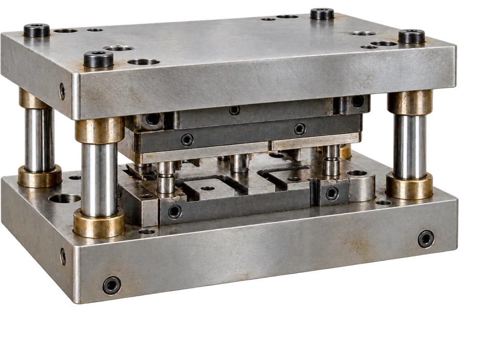
    프레스 금형의 상하형·가이드 포스트·펀치 조립 구조

    프레스 금형 이관: 도면 검토와 보수·개조가 먼저인 이유

    보유한 프레스 금형을 다른 설비로 옮길 때 필요한 도면 대조, 금형 상태 조사, 보수·개조와 시타발을 살펴봅니다. 설비 차이와 남은 생산…
    전기차 급속충전 커넥터의 은색 수핀과 내부 다점 접촉 소켓

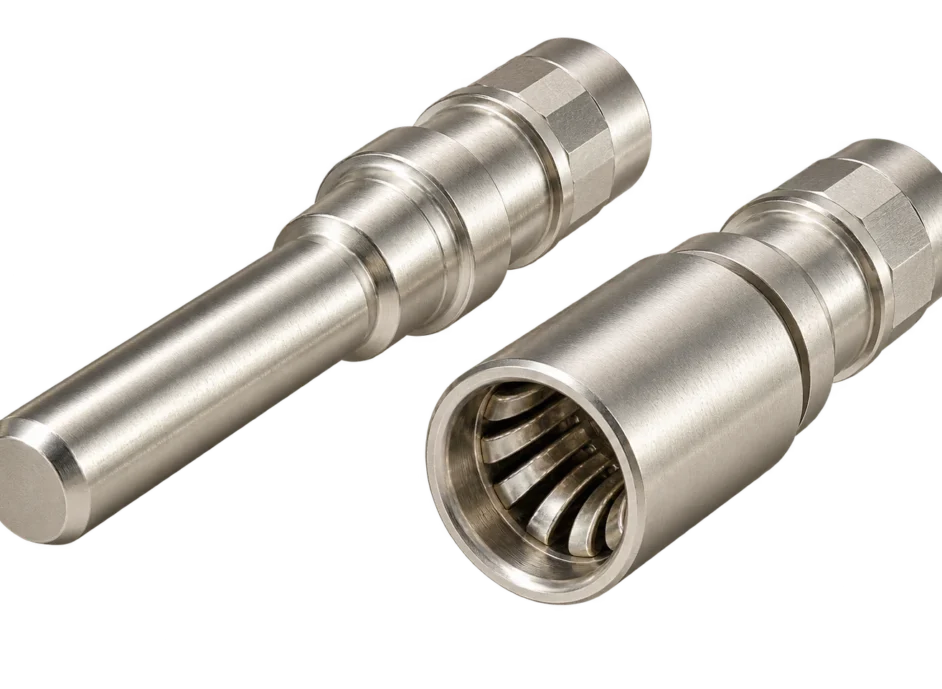
    전기차 급속충전 커넥터 접점: 고전류를 받는 핀과 소켓의 구조

    전기차 급속충전 커넥터 접점은 차량 인렛의 핀과 충전 플러그의 소켓이 만드는 고전류 인터페이스입니다. 눈에 잘 보이지 않는 접촉대, 도금과 케이블…
    구리관과 스테인리스 소켓이 은계 브레이징 접합층으로 연결된 조립 구조

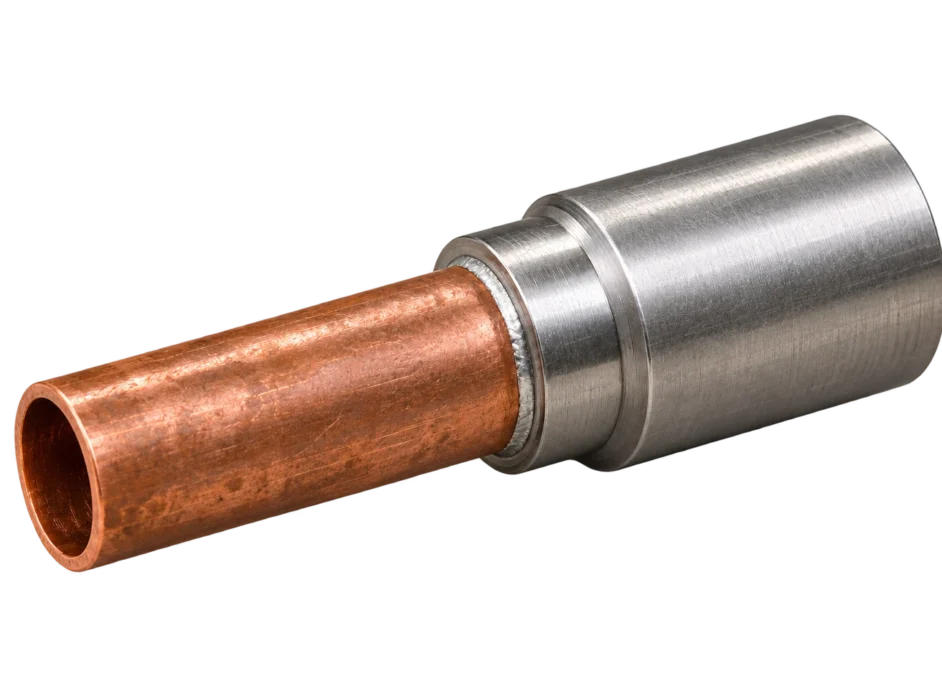
    구리–스테인리스 이종 브레이징: 젖음·열간 간극·계면 내구성

    구리–스테인리스 이종 브레이징 설계에서는 젖음, 열간 간극, 용가재와 공정 관리를 함께 검토해야 합니다.
    LOUVER PANEL / 연결된 후드와 열린 통로

    판금 루버 성형: 개구 형상·금형·압력손실을 연결하는 설계

    루버는 판에 구멍을 많이 만드는 작업을 넘어, 절개한 재료를 원하는 방향으로 세워 공기의 통로와 패널의 구조를 함께 만드는 성형입니다.
    PLATED INTERFACES / 단계 축과 플랜지 부시

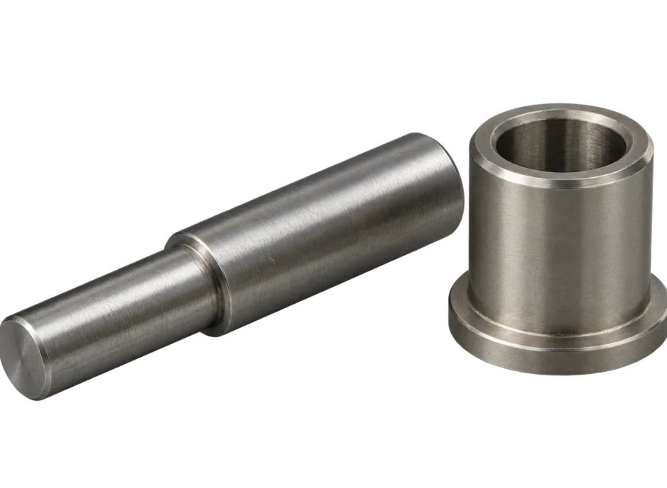
    도금 공차 설계: 기능 치수·두께 분포·완성 검사

    정밀 부품의 표면처리는 재료의 기능을 바꾸면서 조립 공간도 바꿉니다. 외경은 커지고 내경은 작아지며, 마스킹 경계와 국부 성장까지 상대 부품의 움직임에…
    AgW CONTACT / 구리 지지체에 접합된 복합 접점

    은·텅스텐 접점: 복합 조직·침투 제조·접합 품질의 설계

    두 상의 연결이 접점의 성능을 만듭니다.

    연결 준비 중입니다. 현재 전화 연결을 이용하실 수 있습니다.

    ID SOLUTECH
    LET’S TALK ENGINEERING

    무엇을
    도와드릴까요?

    아이디솔루텍의 제품과 제조 공정,
    기술자료에 대해 질문해 주세요.