ELECTRIC RIVET INSULATION
부싱·와셔·성형 공정에서 전기·기계 내구 검증까지
ELECTRIC RIVET INSULATION
하중은 안정적으로 전달하고 원하지 않는 전도 경로는 조립 구조로 관리합니다.
Nonferrous rivet · Bushing · Isolation · Durability
전기차의 작은 리벳 접합부에는 구조 하중, 전기적 경계, 온도와 부식 환경이 함께 작용합니다. 비철금속의 성형성을 활용하면서 절연 부싱과 와셔가 조립 후에도 역할을 유지하도록 설계해야 합니다.
이 글은 금속 체결과 전기 절연의 검토 범위를 나누고, 도면에서 공정·검사·양산 승인으로 이어지는 판단 기준을 정리합니다.
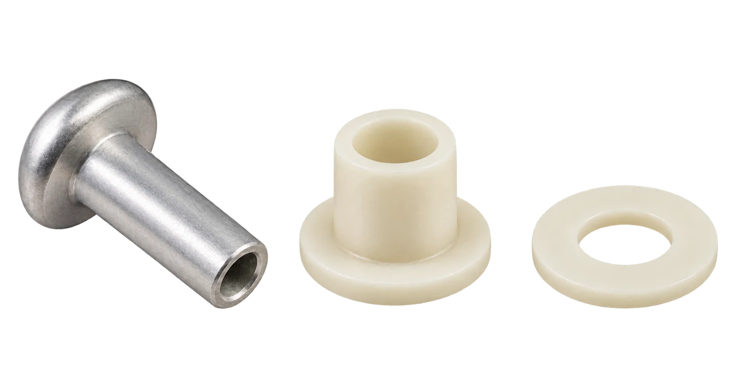
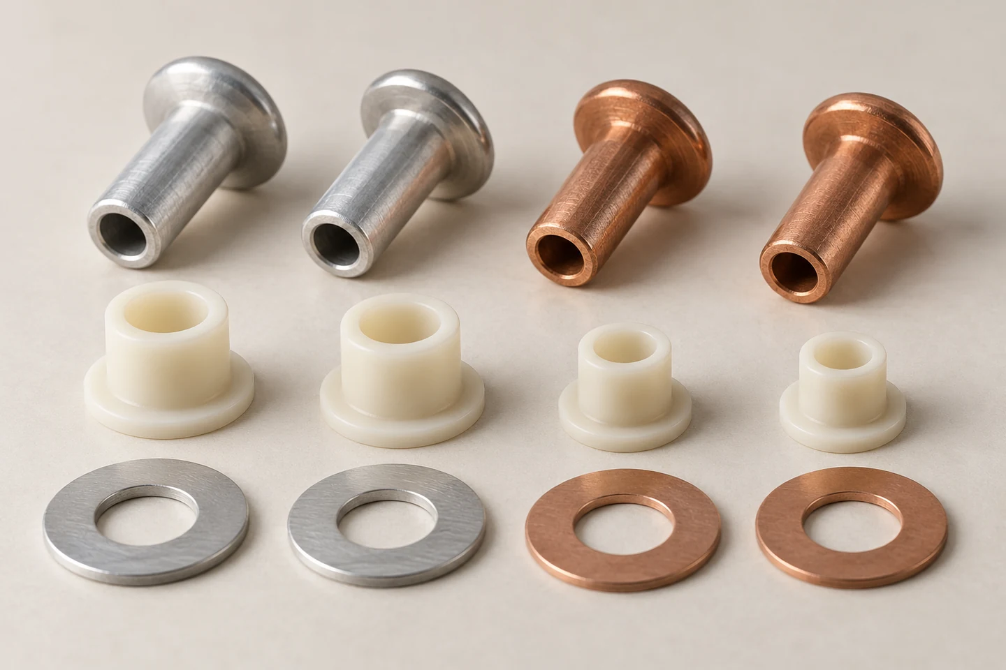
RIVET FAMILY / 알루미늄·구리 리벳과 부싱·와셔
하중 전달과 절연 경계를 정의합니다.
금속이 힘을 전달하고 절연 구조가 전류 경로를 끊습니다.
알루미늄·구리·황동 리벳은 비철금속이지만 전기적으로는 도체입니다. 비자성이나 낮은 밀도를 절연성과 혼동하면 금속 몸통, 머리 또는 성형 꼬리부를 통해 예상하지 못한 전도 경로가 생깁니다. 전기차 체결부에서는 무엇을 연결하고 무엇을 분리할지 먼저 지정해야 합니다.
절연 부싱은 구멍 벽과 리벳 몸통 사이를, 절연 와셔는 머리 또는 성형부와 판재 사이를 분리합니다. 코팅은 조립 손상과 모서리 피복을 포함해 검증된 경우에만 정의된 역할을 맡습니다. 부품 하나의 명칭보다 조립 후 남는 연속 절연 경계가 중요합니다.
배터리팩 외함, 내부 지지대, 전장 모듈은 하중과 전위 관계가 서로 다릅니다. 이 글은 부품 설계·공정 검토의 틀을 다루며 특정 전압 정격이나 차량 적합성을 부여하지 않습니다. ISO 6469-3의 전기 안전 범위와 해당 차량 요구사항은 시스템 승인 단계에서 연결합니다.
전단·인장·박리의 전달 · 도면에 연결면 표시
도체와 절연체의 구분 · 머리·몸통·꼬리 경로 확인
부품과 차량 승인 구분 · 전위·환경·정격 입력
| 검토 항목 | 기술적 의미 | 검증·관리 기준 |
|---|---|---|
| 하중 경로 | 전단·인장·박리의 전달 | 도면에 연결면 표시 |
| 전기 경계 | 도체와 절연체의 구분 | 머리·몸통·꼬리 경로 확인 |
| 적용 범위 | 부품과 차량 승인 구분 | 전위·환경·정격 입력 |
하중 경로
기술적 의미
전단·인장·박리의 전달
검증·관리 기준
도면에 연결면 표시
전기 경계
기술적 의미
도체와 절연체의 구분
검증·관리 기준
머리·몸통·꼬리 경로 확인
적용 범위
기술적 의미
부품과 차량 승인 구분
검증·관리 기준
전위·환경·정격 입력
머리 아래 한 장의 와셔만으로 모든 접촉 경로가 사라지지는 않습니다.
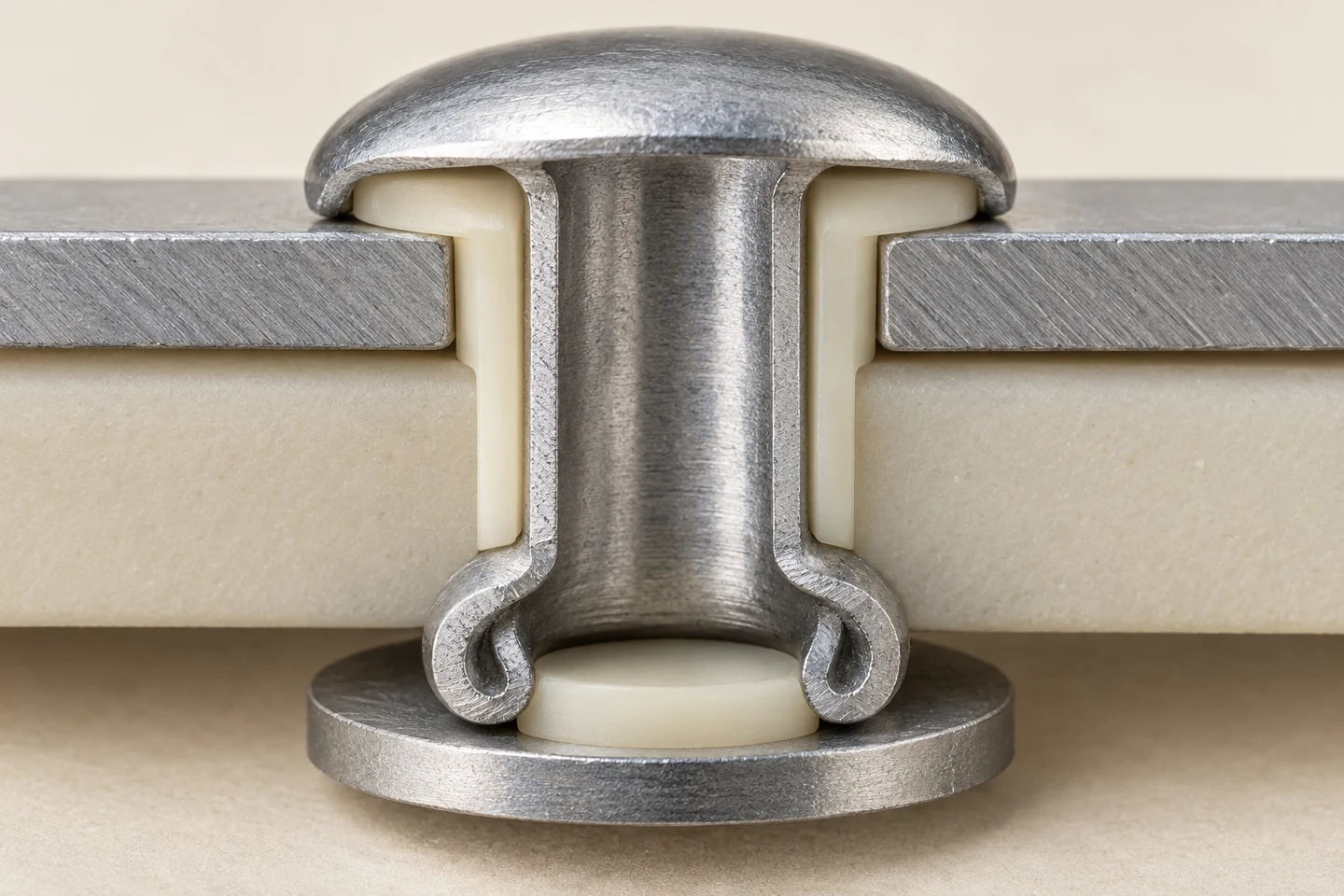
절연 와셔를 추가해도 몸통이 금속 구멍 벽에 닿거나 성형 꼬리부가 반대쪽 판재에 닿으면 경로가 남습니다. 부싱 길이, 플랜지 겹침, 와셔 내경과 변형 후 리벳 직경을 한 단면에서 겹쳐 보아야 합니다. 삽입 전과 성형 후의 경계는 같지 않을 수 있습니다.
판재 간 직접 접촉 역시 검토 대상입니다. 두 판을 서로 절연해야 하는 구조에서는 리벳 주변만 절연해도 다른 면에서 전기적으로 연결될 수 있습니다. 절연 대상이 리벳과 판재인지, 두 판재 사이인지, 고전압 부품과 외함 사이인지 요구서를 명확히 합니다.
실링재나 접착제를 병용하면 수분 침투 경로와 미끄럼이 달라집니다. 그러나 접착층 두께나 경화 상태가 체결 길이와 하중 전달을 바꿀 수 있어 별도 검증이 필요합니다. 조립순서 오류를 줄이는 키 형상과 부품 존재 확인도 설계 단계에서 반영합니다. 단면 사진은 반중공 리벳과 절연 기판의 조합을, 3D는 실체 리벳과 두 금속 부재 사이 절연층을 다룹니다. 두 방식은 머리·몸통·성형부의 전도 경계를 확인한다는 원칙을 공유하지만 허용 하중과 성형 조건은 각각 검증해야 합니다.
몸통과 구멍 벽의 접촉 · 부싱 길이·최소벽 확인
머리·꼬리의 지지면 · 와셔·플랜지 중첩 확인
판재 접촉·금속 이물 · 조립 전체 경계 점검
머리 아래 한 장의 와셔만으로 모든 접촉 경로가 사라지지는 않습니다.
단면 검토는 공칭치에서 끝내지 않습니다. 부품 누락, 뒤집힘과 최대 편심을 포함한 불리한 조합에서도 절연 경계를 확인합니다.
| 검토 항목 | 기술적 의미 | 검증·관리 기준 |
|---|---|---|
| 반경 방향 | 몸통과 구멍 벽의 접촉 | 부싱 길이·최소벽 확인 |
| 축 방향 | 머리·꼬리의 지지면 | 와셔·플랜지 중첩 확인 |
| 우회 경로 | 판재 접촉·금속 이물 | 조립 전체 경계 점검 |
반경 방향
기술적 의미
몸통과 구멍 벽의 접촉
검증·관리 기준
부싱 길이·최소벽 확인
축 방향
기술적 의미
머리·꼬리의 지지면
검증·관리 기준
와셔·플랜지 중첩 확인
우회 경로
기술적 의미
판재 접촉·금속 이물
검증·관리 기준
조립 전체 경계 점검
금속·수지·공차를 하나의 구조로 봅니다.
재료 이름보다 성형성과 장기 하중 특성이 실제 조립을 결정합니다.
리벳 재료는 합금 번호, 조질, 경도와 성형 가능 범위까지 지정합니다. 동일한 알루미늄이라는 이름만으로 꼬리부 변형과 전단 성능을 예측할 수 없습니다. 구리나 황동으로 변경하면 성형 하중뿐 아니라 질량·열팽창·갈바닉 조합도 달라집니다.
절연 부품은 수지 계열과 함께 충전재, 색상, 난연 등급, 공급 형태를 식별합니다. 전기 특성이 필요한 부품에 도전성 개질 등급을 혼용해서는 안 됩니다. 재료 데이터시트의 시험편 수치를 실제 부싱 형상과 조립 상태의 보증값으로 직접 사용하지 않습니다.
고온에서 지속되는 압축, 흡습 또는 냉각수 접촉은 부싱 치수와 지지 조건을 바꿀 수 있습니다. 후보 재료의 시간·온도 의존 특성을 비교한 뒤 실제 조립 하중을 준 시편으로 확인합니다. 짧은 압축강도 시험과 장기 크리프 평가는 서로 다른 질문에 답합니다.
합금·조질·경도 · 소재 로트 추적
수지·충전재·색상 · 정확한 구매 등급
수분·유체·온도 · 노출 후 치수·기능
재료 대체 시 금속만 비교하지 말고 절연재의 공급 등급까지 변경표에 남깁니다. 작은 충전재 차이가 성형과 전기 성능을 동시에 바꿀 수 있습니다.
| 검토 항목 | 기술적 의미 | 검증·관리 기준 |
|---|---|---|
| 리벳 | 합금·조질·경도 | 소재 로트 추적 |
| 절연 부품 | 수지·충전재·색상 | 정확한 구매 등급 |
| 환경 적합성 | 수분·유체·온도 | 노출 후 치수·기능 |
| 장기 하중 | 크리프·응력 완화 | 시간 의존 조립 시험 |
리벳
기술적 의미
합금·조질·경도
검증·관리 기준
소재 로트 추적
절연 부품
기술적 의미
수지·충전재·색상
검증·관리 기준
정확한 구매 등급
환경 적합성
기술적 의미
수분·유체·온도
검증·관리 기준
노출 후 치수·기능
장기 하중
기술적 의미
크리프·응력 완화
검증·관리 기준
시간 의존 조립 시험
JOINT SECTION / 리벳 성형부와 절연 경계의 단면
04 / GEOMETRY & TOLERANCE
공칭 직경이 맞아도 편심과 버가 국부 절연을 소모할 수 있습니다.
리벳 최대 몸통, 부싱 최소 벽, 판재 최소 구멍과 위치도 조합을 함께 검토합니다. 구멍 축이 어긋나면 조립 시 부싱 한쪽을 밀어내고 반대쪽 벽을 얇게 만들 수 있습니다. 직경 공차만으로는 이 상태를 설명하지 못합니다.
금속 구멍의 입구 모서리와 버는 절연재를 절삭하는 날처럼 작용할 수 있습니다. 디버링 형상, 모따기, 청정도를 지정하되 모따기를 지나치게 키워 지지 면적을 잃지 않도록 합니다. 절연재 압출과 금속 간 접촉 흔적은 조립 후 확대 관찰로 확인합니다.
부싱 길이는 너무 짧으면 금속 접촉을 남기고 너무 길면 판재 밀착과 리벳 성형을 방해할 수 있습니다. 실제 그립 두께에 코팅·접착층·와셔까지 포함하고 조립 방향을 표시합니다. 허용 간극은 삽입성, 하중 분담과 전기적 경계를 동시에 만족해야 합니다.
공칭 직경이 맞아도 편심과 버가 국부 절연을 소모할 수 있습니다.
| 검토 항목 | 기술적 의미 | 검증·관리 기준 |
|---|---|---|
| 몸통·구멍 | 최대·최소 직경과 위치도 | 조립 공차 분석 |
| 절연벽 | 편심 후 남는 최소 두께 | 단면·치수 검사 |
| 끝단 | 버·모따기·날카로운 모서리 | 확대 관찰과 세척 |
| 그립 | 판재·코팅·와셔 적층 | 최소·최대 조립 검증 |
몸통·구멍
기술적 의미
최대·최소 직경과 위치도
검증·관리 기준
조립 공차 분석
절연벽
기술적 의미
편심 후 남는 최소 두께
검증·관리 기준
단면·치수 검사
끝단
기술적 의미
버·모따기·날카로운 모서리
검증·관리 기준
확대 관찰과 세척
그립
기술적 의미
판재·코팅·와셔 적층
검증·관리 기준
최소·최대 조립 검증
기계적 체결과 전기적 절연은 서로 다른 검증 항목입니다. 절연 부품의 압축 변형도 관리합니다.
성형과 부식 경로를 관리합니다.
더 큰 성형 하중이 항상 더 안정적인 접합을 만들지는 않습니다.
리벳의 꼬리부가 충분히 펼쳐져야 기계적 체결이 성립하지만, 과도한 성형은 절연재를 짓누르거나 판재를 휘게 할 수 있습니다. 힘·변위 곡선, 최종 머리 높이, 꼬리 형상과 절연재 상태를 같은 시편에서 비교합니다. 최대 힘 하나만으로 합격을 정하지 않습니다.
실체·반중공·블라인드 리벳과 셀프 피어싱 리벳은 성형 원리와 검사 특성이 다릅니다. 셀프 피어싱 리벳의 인터록·잔여 바닥 두께는 해당 공정에서 평가하며, 미리 뚫은 구멍에 부싱을 넣은 리벳 구조의 절연 성능으로 자동 확장하지 않습니다.
금형 중심, 받침 지지와 부품 높이 편차가 성형 안정성을 좌우합니다. 시작·중간·종료 로트와 공구 마모 상태를 포함해 공정 창을 확인하고, 비정상 곡선이 나타나면 원인별 반응 절차를 정합니다. 금형 조건을 바꾼 뒤에는 치수와 전기 경계를 함께 재확인합니다.
힘·변위·속도 · 기록과 공정 창
금형 중심·받침·정렬 · 치구 반복성
꼬리 형상·머리 높이 · 치수·단면
양호 시편의 파형을 저장한 뒤 공구 마모와 부품 누락 시편을 대조하면 모니터링의 검출 범위를 알 수 있습니다. 파형 관리만으로 모든 절연 결함을 찾는다고 가정하지 않습니다.
| 검토 항목 | 기술적 의미 | 검증·관리 기준 |
|---|---|---|
| 성형 입력 | 힘·변위·속도 | 기록과 공정 창 |
| 지지 조건 | 금형 중심·받침·정렬 | 치구 반복성 |
| 금속 결과 | 꼬리 형상·머리 높이 | 치수·단면 |
| 절연 결과 | 눌림·절삭·압출 | 조립 후 경계 확인 |
성형 입력
기술적 의미
힘·변위·속도
검증·관리 기준
기록과 공정 창
지지 조건
기술적 의미
금형 중심·받침·정렬
검증·관리 기준
치구 반복성
금속 결과
기술적 의미
꼬리 형상·머리 높이
검증·관리 기준
치수·단면
절연 결과
기술적 의미
눌림·절삭·압출
검증·관리 기준
조립 후 경계 확인
금속 조합과 전해질이 만나는 실제 노출 면적이 중요합니다.
서로 다른 금속이 전기적으로 연결되고 전해질이 존재하면 갈바닉 부식이 진행될 수 있습니다. 비철 리벳을 사용했다는 사실만으로 이 문제가 사라지지 않습니다. 리벳·판재·와셔·코팅 손상부를 실제 젖는 면적 기준으로 검토합니다.
작은 양극 면적과 큰 음극 면적의 조합은 국부 공격을 집중시킬 수 있습니다. 절연 부싱이 금속 접촉을 줄여도 판재의 다른 체결점이나 도전성 잔류물이 우회 연결을 만들 수 있습니다. 절연 구조, 실링, 배수와 표면 보호를 서로 보완하는 수단으로 설계합니다.
이종금속 조합은 조립체 수준에서 부식 거동을 평가합니다. 실제 도장·성형 손상·틈·노출 면적을 반영한 조립 시편으로 시험계획을 구성하고 자동차 부품의 적용 조건에 맞춰 적합성을 확인합니다.
전기화학적 차이 · 실제 재료·표면 확인
젖는 양극·음극 면적 · 국부 공격 가능성
응축·냉각수·염분 · 침투와 배수 경로
부식 시험 시에는 부품을 분해한 상태와 실제 조립 상태를 구분합니다. 조립 후 생기는 틈과 피복 손상은 단품 시험에서 재현되지 않을 수 있습니다.
| 검토 항목 | 기술적 의미 | 검증·관리 기준 |
|---|---|---|
| 금속 조합 | 전기화학적 차이 | 실제 재료·표면 확인 |
| 면적 비 | 젖는 양극·음극 면적 | 국부 공격 가능성 |
| 전해질 | 응축·냉각수·염분 | 침투와 배수 경로 |
| 우회 연결 | 다른 체결점·이물 | 조립체 전도 경로 |
금속 조합
기술적 의미
전기화학적 차이
검증·관리 기준
실제 재료·표면 확인
면적 비
기술적 의미
젖는 양극·음극 면적
검증·관리 기준
국부 공격 가능성
전해질
기술적 의미
응축·냉각수·염분
검증·관리 기준
침투와 배수 경로
우회 연결
기술적 의미
다른 체결점·이물
검증·관리 기준
조립체 전도 경로
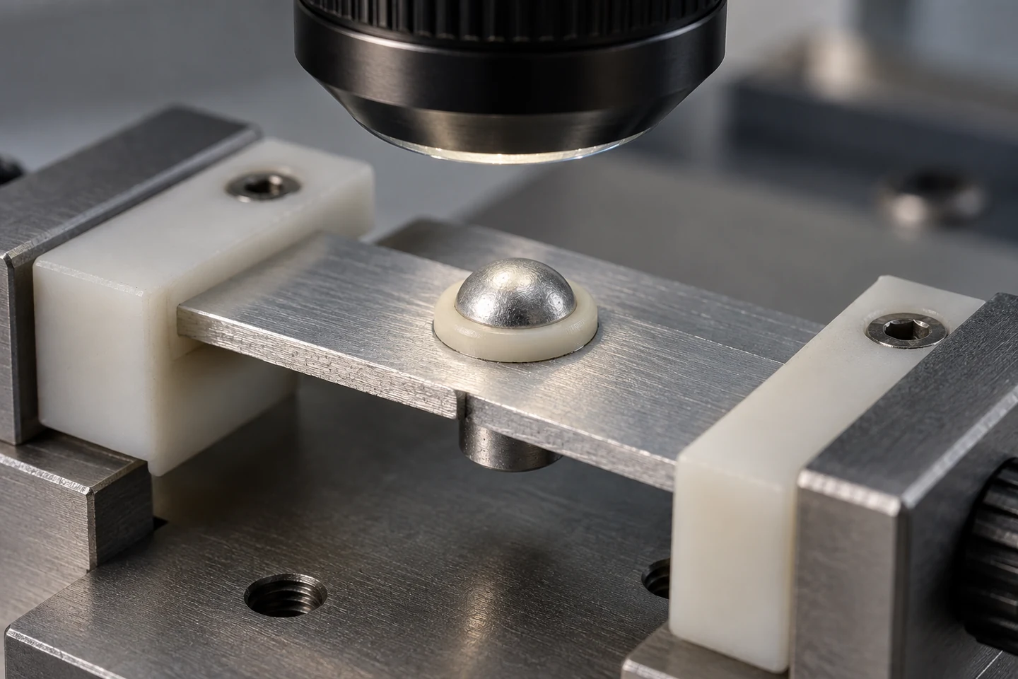
INSPECTION / 리벳 머리와 절연 칼라의 위치 검사
시간·온도·하중을 연결합니다.
초기 밀착이 장기 지지력을 보장하지는 않습니다.
절연재가 지속 압축을 받으면 시간에 따른 변형과 응력 완화가 발생할 수 있습니다. 성형 직후의 머리 간 거리와 사용 후 거리를 비교하고, 유격·판재 미끄럼·절연 경계 변화가 기능에 미치는 영향을 확인합니다. 높은 단기 강도만으로 장기 유지력을 판단하지 않습니다.
금속과 절연재의 열팽창 차이는 온도 반복 중 계면 압력과 간극을 바꿉니다. 부싱이 한 온도에서 잘 맞더라도 다른 온도에서 압축되거나 느슨해질 수 있습니다. 주변 공기 온도뿐 아니라 실제 시편 온도와 안정화 시간을 기록해야 비교가 가능합니다.
IEC 60068-2-14는 온도 변화 시험의 범위를 제시합니다. 구체적인 온도·횟수·체류 시간은 제품 사용 조건에 맞춰 정하고, 시험 전후 강도·유격·절연저항과 외관을 연결합니다. 온도 시험 통과를 진동이나 습윤 내구의 대체 근거로 사용하지 않습니다.
크리프·응력 완화 · 유격·높이 추적
압력·간극 변화 · 최저·최고 상태 확인
시편 온도·체류 · 센서 위치와 기록
초기 밀착이 장기 지지력을 보장하지는 않습니다.
냉각 후 정상 치수로 돌아와도 고온 중 유격이나 국부 접촉이 생겼을 수 있습니다. 필요한 경우 온도 노출 중 기능을 관찰하는 시험을 추가합니다.
| 검토 항목 | 기술적 의미 | 검증·관리 기준 |
|---|---|---|
| 시간 효과 | 크리프·응력 완화 | 유격·높이 추적 |
| 열팽창 차이 | 압력·간극 변화 | 최저·최고 상태 확인 |
| 시험 이력 | 시편 온도·체류 | 센서 위치와 기록 |
| 노출 후 | 기계·전기 성능 | 동일 조건 재측정 |
시간 효과
기술적 의미
크리프·응력 완화
검증·관리 기준
유격·높이 추적
열팽창 차이
기술적 의미
압력·간극 변화
검증·관리 기준
최저·최고 상태 확인
시험 이력
기술적 의미
시편 온도·체류
검증·관리 기준
센서 위치와 기록
노출 후
기술적 의미
기계·전기 성능
검증·관리 기준
동일 조건 재측정
꼬리 직경·높이와 부싱 손상 여부를 함께 검사합니다. 형상 단계는 성형 하중 계산이 아닙니다.
평균 응력은 설계 검토의 시작이며 파괴 모드를 대신하지 않습니다.
리벳 전단, 판재 지압, 순단면 파단, 가장자리 찢김과 머리 인발은 서로 다른 한계입니다. 절연 부싱이 포함되면 금속뿐 아니라 부싱의 압축·전단과 판재 접촉 분포도 고려해야 합니다. 리벳 재료의 인장강도 하나를 조립체 허용 하중으로 바꾸지 않습니다.
평균 전단응력은 실제 전단면적과 하중 분담을 정의한 뒤 계산합니다. 반중공 리벳은 전단면이 중공부인지 실체부인지에 따라 면적이 달라지며, 여러 리벳에는 편심과 강성 차이에 따른 불균등 분담이 생길 수 있습니다. 지압은 접촉 직경과 실제 지지 두께를 별도로 봅니다.
분석 후에는 실제 하중 방향과 고정 조건을 대표하는 시편에서 파단 경로를 확인합니다. 최대 하중뿐 아니라 초기 미끄럼, 영구 변형, 인발과 절연 손상 발생 시점을 기록합니다. 기계적으로 파손되지 않아도 전기 경계를 잃으면 기능상 불합격일 수 있습니다.
F는 정의한 전달 하중, n은 실제로 하중을 나누는 전단면 수, As는 한 면의 유효 전단면적, d는 지압 직경, t는 유효 지지 두께입니다. 균등 분담·평균 응력의 1차 검토이며 편심·국부 접촉·수지 크리프·피로를 직접 예측하지 않습니다.
계산에 사용하는 허용값은 해당 재료·온도·수명 조건에 맞춰 확보합니다. 안전율과 통계적 하한은 제품 설계 기준에 따라 별도로 정합니다.
| 검토 항목 | 기술적 의미 | 검증·관리 기준 |
|---|---|---|
| 전단 | 실체·중공 유효 면적 | 실제 전단면 위치 |
| 지압 | 직경과 지지 두께 | 금속·절연재 분담 |
| 인발·찢김 | 머리·끝거리·판두께 | 하중별 파단 경로 |
| 기능 한계 | 미끄럼·절연 손상 | 최대 하중 이전 관찰 |
전단
기술적 의미
실체·중공 유효 면적
검증·관리 기준
실제 전단면 위치
지압
기술적 의미
직경과 지지 두께
검증·관리 기준
금속·절연재 분담
인발·찢김
기술적 의미
머리·끝거리·판두께
검증·관리 기준
하중별 파단 경로
기능 한계
기술적 의미
미끄럼·절연 손상
검증·관리 기준
최대 하중 이전 관찰
전기와 반복 하중의 유지 성능을 봅니다.
한 가지 전기 시험으로 모든 절연 요구를 설명할 수 없습니다.
절연저항은 지정 전극 사이의 누설 특성을 측정하고, 내전압 시험은 정해진 인가 조건에서 절연 파괴 여부를 확인합니다. 두 시험의 목적과 스트레스 수준은 다릅니다. 측정 전압, 시간, 전극 위치와 온습도를 기록하지 않은 값은 비교하기 어렵습니다.
공간거리와 연면거리는 각각 공기 중과 절연 표면을 따라가는 경로입니다. IEC 60664-1의 절연 협조 범위는 전압, 오염 조건과 고체 절연의 검토 틀을 제공합니다. 구체적인 거리 값을 이 글에서 임의로 정하지 않고 실제 시스템과 적용 규격에 맞춰 결정합니다.
건조한 초기 시편 외에 조립 손상과 환경 노출 후 상태를 검사계획에 포함합니다. 금속 분진, 세척 잔류물 또는 습기가 표면 누설을 바꿀 수 있으므로 보관과 취급도 통제합니다. 기기 내부의 다른 부품을 연결한 상태에서 시험할 때는 시험 경로를 먼저 식별합니다.
한 가지 전기 시험으로 모든 절연 요구를 설명할 수 없습니다.
전기 시험의 합격 수치는 차량 요구에서 내려오는 입력입니다. 부품 공급 검토 단계에서 미정인 값은 시험계획의 확인 항목으로 관리합니다.
| 검토 항목 | 기술적 의미 | 검증·관리 기준 |
|---|---|---|
| 절연저항 | 전극 간 누설 특성 | 전압·시간·환경 |
| 내전압 | 지정 스트레스의 견딤 | 파괴·플래시오버 판정 |
| 거리 | 공간·표면 경로 | 최악 형상과 오염 |
| 노출 후 | 조립·환경 손상 | 초기와 동일 조건 비교 |
절연저항
기술적 의미
전극 간 누설 특성
검증·관리 기준
전압·시간·환경
내전압
기술적 의미
지정 스트레스의 견딤
검증·관리 기준
파괴·플래시오버 판정
거리
기술적 의미
공간·표면 경로
검증·관리 기준
최악 형상과 오염
노출 후
기술적 의미
조립·환경 손상
검증·관리 기준
초기와 동일 조건 비교
정적 강도가 높아도 미세 미끄럼과 국부 균열은 따로 확인해야 합니다.
진동에서 접합부는 전단만 받지 않고 판재의 굽힘과 리벳 주변 접촉 변화도 겪습니다. 미세 미끄럼은 구멍 확대, 표면 마모와 부싱 손상으로 이어질 수 있습니다. 하중 경로가 편심이면 단순 인장 시편과 실제 조립체의 손상이 달라집니다.
셀프 피어싱 리벳에서는 정적 강도 순위와 피로 순위가 다를 수 있으므로 파단 위치를 함께 확인합니다. 소재·적층·리벳 형상과 부싱을 포함한 구조가 다르면 수명 수치를 그대로 옮기지 않습니다. 대표성 있는 시험으로 실제 고장 경로를 검토합니다.
진동 또는 반복 하중 전후에 유격·머리 위치·절연저항을 추적하고, 종료 후 분해 관찰과 단면을 연결합니다. 시험이 중단 없이 끝난 시편도 균열이나 국부 절연 절삭이 없는지 확인합니다. 가진 조건은 설치 위치와 실측 또는 승인된 환경 프로파일에 맞춥니다.
전단·굽힘·편심 · 실제 설치 조건
유격·위치 변화 · 주기별 추적
리벳·판재·부싱 · 종료 후 분해·단면
초기 강도와 내구 후 잔존 성능을 같은 로트 체계로 연결합니다. 파단면 사진에는 시편 방향과 하중 방향을 함께 남깁니다.
| 검토 항목 | 기술적 의미 | 검증·관리 기준 |
|---|---|---|
| 하중 입력 | 전단·굽힘·편심 | 실제 설치 조건 |
| 진행 지표 | 유격·위치 변화 | 주기별 추적 |
| 파단 경로 | 리벳·판재·부싱 | 종료 후 분해·단면 |
| 전기 유지 | 경계 마모·우회 접촉 | 노출 후 절연 검증 |
하중 입력
기술적 의미
전단·굽힘·편심
검증·관리 기준
실제 설치 조건
진행 지표
기술적 의미
유격·위치 변화
검증·관리 기준
주기별 추적
파단 경로
기술적 의미
리벳·판재·부싱
검증·관리 기준
종료 후 분해·단면
전기 유지
기술적 의미
경계 마모·우회 접촉
검증·관리 기준
노출 후 절연 검증
검사와 변경 기록으로 양산을 승인합니다.
외관·단면·기능 시험은 서로 다른 정보를 제공합니다.
외관검사는 누락, 편심, 비정상 꼬리 형상과 절연재 압출을 빠르게 찾는 데 유용합니다. 내부 최소벽과 감춰진 금속 접촉은 외관만으로 확인하기 어렵습니다. 개발 단계에서 단면과 전기 측정의 상관관계를 확보해 양산 검사 조합을 정합니다.
치수 검사는 기준면과 측정 압력을 고정합니다. 연한 수지 플랜지를 강하게 눌러 측정하면 실제 두께보다 작게 읽을 수 있습니다. 검사자·치구·온도·시편 상태에 따른 산포를 확인하여 공정 편차와 측정 편차를 구분합니다.
염수분무 결과를 실제 수명으로 환산하지 않습니다. ASTM B117의 공개 설명도 독립적인 염수분무 데이터와 자연 환경 성능의 상관 한계를 밝힙니다. 부식 노출은 실제 조립의 취약 경로를 찾는 시험으로 설계하고 기능 유지 판정을 함께 남깁니다.
누락·편심·압출 · 표준 사진·위치
머리 높이·그립·유격 · 측정력·기준면
절연 연속성·국부 손상 · 단면과 상관 분석
외관·단면·기능 시험은 서로 다른 정보를 제공합니다.
검사 기록에서 관찰 사실과 합격 판정을 구분하면 재발 방지에 도움이 됩니다. 불합격 시편은 청소·분해 전에 상태와 위치를 보존합니다.
| 검토 항목 | 기술적 의미 | 검증·관리 기준 |
|---|---|---|
| 외관 | 누락·편심·압출 | 표준 사진·위치 |
| 치수 | 머리 높이·그립·유격 | 측정력·기준면 |
| 내부 | 절연 연속성·국부 손상 | 단면과 상관 분석 |
| 환경 기능 | 부식 후 유지 성능 | 절연·강도·유격 |
외관
기술적 의미
누락·편심·압출
검증·관리 기준
표준 사진·위치
치수
기술적 의미
머리 높이·그립·유격
검증·관리 기준
측정력·기준면
내부
기술적 의미
절연 연속성·국부 손상
검증·관리 기준
단면과 상관 분석
환경 기능
기술적 의미
부식 후 유지 성능
검증·관리 기준
절연·강도·유격
좋은 시편의 재현 조건까지 남겨야 안정적인 생산이 됩니다.
승인 도면에는 금속 등급과 조질, 절연 부품의 정확한 재료, 구멍·그립·버 기준과 조립 방향을 포함합니다. 성형 장비의 설정값만 남기지 말고 실제 힘·변위와 결과 형상을 연결합니다. 검사 위치, 표본과 기능 한계도 제품별로 확정합니다.
리벳 공급처, 부싱 수지, 색상·충전재, 도금 또는 공구를 변경하면 영향받는 하중 경로와 절연 경계를 먼저 표시합니다. 단순 치수 재검사로 충분한 변경과 환경·내구 재검증이 필요한 변경을 구분합니다. 변경 전후 로트는 비교 가능한 상태로 추적합니다.
아이디솔루텍에 개발을 의뢰할 때에는 체결부 단면, 상대재, 기계 하중, 분리할 전위, 온습도·유체 노출, 수량과 요구 검사를 함께 전달해 주세요. 이를 바탕으로 절연 구조와 리벳 성형 조건을 함께 검토하고 시제품 평가 범위를 구체화할 수 있습니다.
하중·전위·환경·치수 · 승인 범위 확정
부품·금형·힘·변위 · 양호 조건 재현
단면·전기·기계·내구 · 시편과 로트 연결
기존 불량이 있으면 고장 시점과 사용 조건을 정상품 비교 자료와 함께 제공해 주세요. 작은 접합부라도 기계·전기·환경의 연결 관계를 알아야 원인을 좁힐 수 있습니다.
| 검토 항목 | 기술적 의미 | 검증·관리 기준 |
|---|---|---|
| 설계 입력 | 하중·전위·환경·치수 | 승인 범위 확정 |
| 공정 관리 | 부품·금형·힘·변위 | 양호 조건 재현 |
| 품질 증거 | 단면·전기·기계·내구 | 시편과 로트 연결 |
| 변경 관리 | 재료·공급처·공구 | 영향 평가와 재승인 |
설계 입력
기술적 의미
하중·전위·환경·치수
검증·관리 기준
승인 범위 확정
공정 관리
기술적 의미
부품·금형·힘·변위
검증·관리 기준
양호 조건 재현
품질 증거
기술적 의미
단면·전기·기계·내구
검증·관리 기준
시편과 로트 연결
변경 관리
기술적 의미
재료·공급처·공구
검증·관리 기준
영향 평가와 재승인
체결부 도면, 상대재, 하중·전위·환경 조건을 공유해 주세요. 절연 구조와 성형 공정, 시제품 검증 범위를 함께 검토합니다.
Share joint drawings, mating materials, loads, potentials and environment to define insulation architecture, forming trials and prototype validation.
ELECTRIC RIVET INSULATION
Transfer structural loads while controlling unintended conductive paths through the assembled architecture.
Nonferrous rivet · Bushing · Isolation · Durability
ENGLISH EDITION
Reliable attachment. Defined electrical boundaries.
A small riveted EV joint combines structural loading, electrical boundaries, temperature and corrosion exposure. Nonferrous formability must be paired with bushings and washers that retain their insulating function after installation.
This article separates fastening and isolation requirements and connects drawings with processing, inspection and production approval.
RIVET FAMILY / Aluminum and copper rivets with bushings and washers
Define load transfer and electrical boundaries.
The metal transfers force; the insulation interrupts the current path.
Aluminum, copper and brass rivets are nonferrous metals, but they conduct electricity. Confusing low density or nonmagnetic behavior with insulation leaves possible current paths through the shank, head or formed tail. An electric-vehicle joint must first identify the elements to connect mechanically and separate electrically.
A shoulder bushing separates the shank from the hole wall; an insulating washer separates a head or formed tail from a plate. Coatings can serve a defined role only after assembly damage and edge coverage have been assessed. The decisive feature is the continuous insulation boundary remaining after assembly.
Battery enclosures, internal supports and electronic modules have different loads and electrical potentials. This discussion provides a component-engineering framework rather than a voltage rating or vehicle qualification. Connect the electrical-safety scope of ISO 6469-3 with the applicable vehicle requirements during system approval.
Transfer of shear, tension and peel. Mark connected surfaces
Conductors versus insulators. Review head, shank and tail paths
Component and vehicle approval. Define potentials and environment
| Review item | Engineering significance | Verification or control |
|---|---|---|
| Load path | Transfer of shear, tension and peel | Mark connected surfaces |
| Electrical boundary | Conductors versus insulators | Review head, shank and tail paths |
| Application scope | Component and vehicle approval | Define potentials and environment |
Load path
Engineering significance
Transfer of shear, tension and peel
Verification or control
Mark connected surfaces
Electrical boundary
Engineering significance
Conductors versus insulators
Verification or control
Review head, shank and tail paths
Application scope
Engineering significance
Component and vehicle approval
Verification or control
Define potentials and environment
A washer beneath the head does not eliminate every contact path.
Even with a head washer, the shank can touch the metal bore or the formed tail can touch the opposite plate. Overlay bushing length, flange overlap, washer bore and final rivet diameter in a common section. Boundaries before insertion may differ from those after forming.
Direct plate-to-plate contact also matters. If the plates must be isolated from each other, insulating only the rivet does not prevent a conductive path elsewhere. State whether the requirement concerns rivet-to-plate, plate-to-plate or high-voltage-part-to-enclosure isolation.
Sealant or adhesive changes moisture entry and joint slip. Its thickness and cure condition may also alter grip length and load transfer, requiring separate evaluation. Features that discourage reversed assembly and checks for missing components belong in the design review. The section photograph uses a semi-tubular rivet and insulating base, while the 3D assembly uses a solid rivet and an insulating separator between two metallic members. Both require examination of head, shank and formed-end conductive paths, but loads and forming conditions require separate validation.
Shank-to-hole contact. Check sleeve length and minimum wall
Head and tail bearing faces. Check washer and flange overlap
Plate contact and metal debris. Inspect the complete assembly boundary
A washer beneath the head does not eliminate every contact path.
Do not stop at nominal dimensions. Examine missing or reversed parts and unfavorable eccentricity combinations.
| Review item | Engineering significance | Verification or control |
|---|---|---|
| Radial direction | Shank-to-hole contact | Check sleeve length and minimum wall |
| Axial direction | Head and tail bearing faces | Check washer and flange overlap |
| Bypass paths | Plate contact and metal debris | Inspect the complete assembly boundary |
Radial direction
Engineering significance
Shank-to-hole contact
Verification or control
Check sleeve length and minimum wall
Axial direction
Engineering significance
Head and tail bearing faces
Verification or control
Check washer and flange overlap
Bypass paths
Engineering significance
Plate contact and metal debris
Verification or control
Inspect the complete assembly boundary
Review metal, polymer and tolerances together.
Formability and sustained-load behavior govern the assembled joint.
Identify rivet alloy, temper, hardness and permissible forming condition. The word aluminum alone cannot predict tail formation or shear performance. Substitution with copper or brass changes forming force, mass, thermal expansion and the galvanic couple.
For insulating parts, identify resin family together with filler, color, flame classification and supply form. Conductively modified grades must not be confused with electrically insulating grades. Datasheet values measured on standard specimens are not direct guarantees for the actual bushing geometry and assembly.
Sustained compression at temperature, moisture uptake or coolant exposure can change bushing dimensions and support. Compare time- and temperature-dependent data, then test specimens under representative assembly loads. Short-term compressive strength and long-term creep address different questions.
Alloy, temper and hardness. Trace material lots
Resin, filler and color. Control the exact purchased grade
Moisture, fluid and temperature. Post-exposure dimensions and function
Track the insulating compound as well as the metal when substituting materials. A filler change can affect both processing and electrical behavior.
| Review item | Engineering significance | Verification or control |
|---|---|---|
| Rivet | Alloy, temper and hardness | Trace material lots |
| Insulating part | Resin, filler and color | Control the exact purchased grade |
| Environmental fit | Moisture, fluid and temperature | Post-exposure dimensions and function |
| Sustained loading | Creep and stress relaxation | Time-dependent assembly testing |
Rivet
Engineering significance
Alloy, temper and hardness
Verification or control
Trace material lots
Insulating part
Engineering significance
Resin, filler and color
Verification or control
Control the exact purchased grade
Environmental fit
Engineering significance
Moisture, fluid and temperature
Verification or control
Post-exposure dimensions and function
Sustained loading
Engineering significance
Creep and stress relaxation
Verification or control
Time-dependent assembly testing
JOINT SECTION / Formed rivet and insulating interfaces
04 / GEOMETRY & TOLERANCE
Nominal fit can conceal local loss of insulation from eccentricity and burrs.
Evaluate maximum shank size, minimum bushing wall, minimum plate hole and positional variation together. Misaligned holes can displace the bushing and reduce its wall locally. Diameter tolerances alone do not describe this condition.
A metal edge or burr can cut into the insulation. Specify deburring, chamfer and cleanliness without sacrificing excessive bearing area. Examine the assembled joint for polymer extrusion and evidence of unintended metal contact.
A short sleeve may leave exposed metal contact; an overly long sleeve may prevent proper seating and rivet formation. Include coatings, adhesive and washers in the grip stack and define orientation. Clearance must satisfy insertion, load sharing and electrical separation simultaneously.
Nominal fit can conceal local loss of insulation from eccentricity and burrs.
| Review item | Engineering significance | Verification or control |
|---|---|---|
| Shank and hole | Size extremes and position | Assembly tolerance analysis |
| Insulating wall | Minimum wall after eccentricity | Sections and dimensional checks |
| Edges | Burr, chamfer and sharp corners | Magnified inspection and cleaning |
| Grip | Plates, coatings and washers | Minimum and maximum stack trials |
Shank and hole
Engineering significance
Size extremes and position
Verification or control
Assembly tolerance analysis
Insulating wall
Engineering significance
Minimum wall after eccentricity
Verification or control
Sections and dimensional checks
Edges
Engineering significance
Burr, chamfer and sharp corners
Verification or control
Magnified inspection and cleaning
Grip
Engineering significance
Plates, coatings and washers
Verification or control
Minimum and maximum stack trials
Mechanical retention and electrical insulation require separate validation, including compression of the insulating parts.
Control forming and corrosion paths.
Higher forming force does not always produce a more reliable joint.
The tail must form sufficiently to retain the assembly, but excessive forming can crush insulation or bend the sheet. Compare force–displacement history, final head height, tail shape and insulator condition on the same specimens. Peak force alone is not an acceptance criterion.
Solid, semi-tubular, blind and self-piercing rivets have different mechanisms and inspection features. Evaluate interlock and residual bottom thickness for the self-piercing process; these features do not establish insulation performance for a predrilled, bushed joint.
Tool alignment, support and part-height variation affect forming stability. Characterize the process window across production stages and tool wear, with defined responses to abnormal traces. Recheck geometry and electrical boundaries after tooling changes.
Force, displacement and speed. Traces and process window
Tool center, anvil and alignment. Fixture repeatability
Tail shape and head height. Dimensions and sections
Compare reference traces with tool-wear and missing-part specimens to establish monitoring capability. Do not assume trace monitoring detects every insulation defect.
| Review item | Engineering significance | Verification or control |
|---|---|---|
| Forming input | Force, displacement and speed | Traces and process window |
| Support | Tool center, anvil and alignment | Fixture repeatability |
| Metal result | Tail shape and head height | Dimensions and sections |
| Insulation result | Crushing, cutting and extrusion | Post-assembly boundary review |
Forming input
Engineering significance
Force, displacement and speed
Verification or control
Traces and process window
Support
Engineering significance
Tool center, anvil and alignment
Verification or control
Fixture repeatability
Metal result
Engineering significance
Tail shape and head height
Verification or control
Dimensions and sections
Insulation result
Engineering significance
Crushing, cutting and extrusion
Verification or control
Post-assembly boundary review
The exposed areas and electrolyte path matter with the metal pair.
Galvanic corrosion can occur when dissimilar metals are electrically connected in an electrolyte. Choosing a nonferrous rivet does not remove that condition. Review the rivet, plate, washer and damaged coating using the areas actually exposed to moisture.
A small anodic area coupled to a large cathodic area can concentrate attack. Even if a bushing interrupts local contact, another attachment or conductive residue can create a bypass. Insulation, sealing, drainage and surface protection should work together.
Evaluate dissimilar-metal corrosion at assembly level. Plan representative specimens incorporating coatings, forming damage, crevices and exposed areas, then verify suitability for the actual automotive application.
Electrochemical difference. Actual materials and surfaces
Wetted anode and cathode. Potential concentration of attack
Condensate, coolant and salt. Ingress and drainage
Distinguish isolated-part tests from assembled-joint tests. Crevices and coating damage created by installation may be absent on separate parts.
| Review item | Engineering significance | Verification or control |
|---|---|---|
| Metal pair | Electrochemical difference | Actual materials and surfaces |
| Area ratio | Wetted anode and cathode | Potential concentration of attack |
| Electrolyte | Condensate, coolant and salt | Ingress and drainage |
| Bypass connection | Other fasteners and debris | Assembly conductive paths |
Metal pair
Engineering significance
Electrochemical difference
Verification or control
Actual materials and surfaces
Area ratio
Engineering significance
Wetted anode and cathode
Verification or control
Potential concentration of attack
Electrolyte
Engineering significance
Condensate, coolant and salt
Verification or control
Ingress and drainage
Bypass connection
Engineering significance
Other fasteners and debris
Verification or control
Assembly conductive paths
INSPECTION / Head alignment and insulating-collar inspection
Connect time, temperature and loading.
Initial seating does not establish sustained retention.
An insulator under sustained compression can creep and relax stress. Compare head-to-tail dimensions immediately after forming and after exposure, then examine play, plate slip and changes in the insulation boundary. High short-term strength does not establish long-term retention.
Differential thermal expansion changes interface pressure and clearance during cycling. A bushing that fits at one temperature may become compressed or loose at another. Record specimen temperature and stabilization time, not only chamber-air settings.
IEC 60068-2-14 defines a scope for temperature-change testing. Select severity, cycles and dwell from the product environment, then connect strength, play, insulation resistance and appearance before and after exposure. Temperature testing does not replace vibration or wet-environment durability.
Creep and stress relaxation. Track play and height
Pressure and clearance changes. Review hot and cold conditions
Specimen temperature and dwell. Sensor positions and records
Initial seating does not establish sustained retention.
Recovery of room-temperature dimensions does not exclude hot-state movement or contact. Observe function during exposure where the failure mode requires it.
| Review item | Engineering significance | Verification or control |
|---|---|---|
| Time effects | Creep and stress relaxation | Track play and height |
| Expansion mismatch | Pressure and clearance changes | Review hot and cold conditions |
| Exposure history | Specimen temperature and dwell | Sensor positions and records |
| After exposure | Mechanical and electrical function | Repeat at matched conditions |
Time effects
Engineering significance
Creep and stress relaxation
Verification or control
Track play and height
Expansion mismatch
Engineering significance
Pressure and clearance changes
Verification or control
Review hot and cold conditions
Exposure history
Engineering significance
Specimen temperature and dwell
Verification or control
Sensor positions and records
After exposure
Engineering significance
Mechanical and electrical function
Verification or control
Repeat at matched conditions
Inspect tail diameter, height and bushing damage together. The stages do not calculate forming force.
Average stress begins the review; it does not identify every failure mode.
Rivet shear, plate bearing, net-section failure, edge tear-out and head pull-through are different limits. A bushed joint also requires assessment of polymer compression, shear and bearing distribution. A rivet tensile-strength value cannot simply become an assembly allowable load.
Calculate average shear stress only after defining the actual shear area and load sharing. In a semi-tubular rivet, the relevant section may be solid or hollow; a multi-rivet group can share load unevenly because of eccentricity and stiffness. Bearing uses contact diameter and effective supporting thickness separately.
Then test representative loading directions and restraints to identify failure paths. Record initial slip, permanent deformation, pull-through and the onset of insulation damage as well as peak load. A mechanically intact joint can still fail functionally if electrical separation is lost.
F is the defined transmitted load, n the participating shear planes, As the effective area per plane, d the bearing diameter and t the effective support thickness. These are first-order average-stress checks with assumed load sharing, not direct predictions of eccentric contact, polymer creep or fatigue.
Obtain allowables for the actual material, temperature and life condition. Establish safety factors and statistical lower bounds under the product design rules.
| Review item | Engineering significance | Verification or control |
|---|---|---|
| Shear | Solid or hollow effective area | Locate the actual shear plane |
| Bearing | Diameter and support thickness | Metal and insulator load sharing |
| Pull-through and tear-out | Head, edge distance and thickness | Failure path by load case |
| Functional limit | Slip and insulation damage | Observe before peak load |
Shear
Engineering significance
Solid or hollow effective area
Verification or control
Locate the actual shear plane
Bearing
Engineering significance
Diameter and support thickness
Verification or control
Metal and insulator load sharing
Pull-through and tear-out
Engineering significance
Head, edge distance and thickness
Verification or control
Failure path by load case
Functional limit
Engineering significance
Slip and insulation damage
Verification or control
Observe before peak load
Assess electrical and cyclic-load retention.
One electrical test cannot represent every insulation requirement.
Insulation resistance measures leakage between specified electrodes; dielectric withstand checks for breakdown under a defined applied stress. Their purposes and stresses differ. Results need voltage, duration, electrode position, temperature and humidity to be comparable.
Clearance follows a path through air; creepage follows an insulating surface. The scope of IEC 60664-1 provides a framework for insulation coordination and solid insulation. Determine actual distances from the system and applicable requirements rather than assigning arbitrary values here.
Include assembly damage and post-environment condition as well as dry initial specimens. Metal debris, cleaning residue and moisture can change surface leakage, so control handling and storage. Identify test paths before testing with other device components still connected.
One electrical test cannot represent every insulation requirement.
Electrical acceptance limits are inputs from vehicle requirements. Keep unresolved values as explicit test-plan decisions during component development.
| Review item | Engineering significance | Verification or control |
|---|---|---|
| Insulation resistance | Leakage between electrodes | Voltage, duration and environment |
| Dielectric withstand | Defined electrical stress | Breakdown and flashover criteria |
| Spacing | Air and surface paths | Worst geometry and contamination |
| After exposure | Assembly and environmental damage | Compare with matched initial conditions |
Insulation resistance
Engineering significance
Leakage between electrodes
Verification or control
Voltage, duration and environment
Dielectric withstand
Engineering significance
Defined electrical stress
Verification or control
Breakdown and flashover criteria
Spacing
Engineering significance
Air and surface paths
Verification or control
Worst geometry and contamination
After exposure
Engineering significance
Assembly and environmental damage
Verification or control
Compare with matched initial conditions
High static strength does not resolve microslip or local cracking.
A vibrating joint experiences sheet bending and changing contact around the rivet as well as shear. Microslip can enlarge holes, wear surfaces and damage bushings. Eccentric load paths can make a simple tension specimen unrepresentative of the assembly.
In self-piercing rivets, static-strength ranking and fatigue ranking need not coincide, so assess fracture location as well. Different material stacks, rivet geometries and bushed isolation joints do not share interchangeable life values. Use representative testing and failure-path analysis.
Track play, head position and insulation resistance before and after vibration or cyclic loading, followed by disassembly and sections. Even specimens completing the test require examination for cracks and local cutting of insulation. Match excitation to the installation and measured or approved environmental profile.
Shear, bending and eccentricity. Representative installation
Play and position change. Track through the exposure
Rivet, sheet and bushing. Disassembly and sectioning
Link initial strength and retained performance through the same lot records. Record specimen and loading directions with fracture photographs.
| Review item | Engineering significance | Verification or control |
|---|---|---|
| Load input | Shear, bending and eccentricity | Representative installation |
| Progress indicators | Play and position change | Track through the exposure |
| Failure path | Rivet, sheet and bushing | Disassembly and sectioning |
| Electrical retention | Boundary wear and bypass contact | Post-exposure insulation checks |
Load input
Engineering significance
Shear, bending and eccentricity
Verification or control
Representative installation
Progress indicators
Engineering significance
Play and position change
Verification or control
Track through the exposure
Failure path
Engineering significance
Rivet, sheet and bushing
Verification or control
Disassembly and sectioning
Electrical retention
Engineering significance
Boundary wear and bypass contact
Verification or control
Post-exposure insulation checks
Release production through inspection and change records.
Appearance, sections and functional tests provide different evidence.
Visual inspection efficiently finds missing parts, eccentricity, abnormal tails and extruded insulation. It cannot reliably establish hidden minimum wall or internal metal contact. Correlate sections with electrical measurements during development to define the production inspection mix.
Fix datums and measuring force. Compressing a soft polymer flange during measurement can understate thickness. Assess variation from operators, fixtures, temperature and specimen condition to distinguish measurement variation from process variation.
Do not convert salt-spray hours directly into service life. The published ASTM B117 discussion notes the limitations of standalone salt-spray correlation with natural exposure. Design corrosion tests to expose vulnerable assembly paths and record retained function.
Missing parts, offset and extrusion. Reference images and locations
Head height, grip and play. Measuring force and datums
Insulation continuity and local damage. Sections and correlation
Appearance, sections and functional tests provide different evidence.
Separate observed features from acceptance decisions in inspection records. Preserve failed-part condition and location before cleaning or disassembly.
| Review item | Engineering significance | Verification or control |
|---|---|---|
| Appearance | Missing parts, offset and extrusion | Reference images and locations |
| Dimensions | Head height, grip and play | Measuring force and datums |
| Internal condition | Insulation continuity and local damage | Sections and correlation |
| Environmental function | Retained performance after corrosion | Insulation, strength and play |
Appearance
Engineering significance
Missing parts, offset and extrusion
Verification or control
Reference images and locations
Dimensions
Engineering significance
Head height, grip and play
Verification or control
Measuring force and datums
Internal condition
Engineering significance
Insulation continuity and local damage
Verification or control
Sections and correlation
Environmental function
Engineering significance
Retained performance after corrosion
Verification or control
Insulation, strength and play
Stable production needs the conditions that reproduce the approved sample.
The approved drawing should identify metal grade and temper, exact insulation compound, hole and grip dimensions, edge criteria and orientation. Link machine settings with actual force–displacement traces and resulting geometry. Establish product-specific inspection locations, sampling and functional limits.
For a change in rivet supplier, bushing resin, filler, color, coating or tool, first identify affected load paths and insulation boundaries. Distinguish changes needing dimensional confirmation from those requiring environmental or endurance revalidation. Retain comparable lot records before and after the change.
For an ID SOLUTECH development review, provide the joint section, mating materials, mechanical loads, potentials to isolate, temperature, humidity, fluid exposure, quantities and inspection requirements. These inputs support a combined review of insulation architecture, rivet forming and prototype evaluation.

Load, potential, environment and geometry. Define approval scope
Parts, tools, force and displacement. Reproduce approved conditions
Sections, electrical, mechanical and endurance. Link samples and lots
For an existing failure, include timing, operating conditions and a sound comparison. Mechanical, electrical and environmental relationships are needed to narrow the cause.
| Review item | Engineering significance | Verification or control |
|---|---|---|
| Design input | Load, potential, environment and geometry | Define approval scope |
| Process control | Parts, tools, force and displacement | Reproduce approved conditions |
| Quality evidence | Sections, electrical, mechanical and endurance | Link samples and lots |
| Change control | Material, supplier and tooling | Impact assessment and reapproval |
Design input
Engineering significance
Load, potential, environment and geometry
Verification or control
Define approval scope
Process control
Engineering significance
Parts, tools, force and displacement
Verification or control
Reproduce approved conditions
Quality evidence
Engineering significance
Sections, electrical, mechanical and endurance
Verification or control
Link samples and lots
Change control
Engineering significance
Material, supplier and tooling
Verification or control
Impact assessment and reapproval
비철 리벳은 도체이며, 절연은 부싱·와셔·피복과 조립 구조가 만듭니다. 하중 전달을 확보하면서 성형 손상, 크리프, 열팽창 차이와 습윤 환경에서도 연속 절연 경계를 유지하는 것이 핵심입니다. 단품 재료 시험과 조립체·차량 적합성의 범위를 구분하여 검증합니다.
01 / 비철·비자성 특성을 전기 절연성과 혼동하지 않습니다.
02 / 리벳 몸통·머리·꼬리와 판재 간 우회 경로를 모두 확인합니다.
03 / 금속 합금·조질과 절연 수지의 정확한 등급을 지정합니다.
04 / 최악 공차·버·편심에서 남는 최소 절연벽을 검토합니다.
05 / 힘·변위·성형 형상과 절연 손상을 같은 시편에서 연결합니다.
06 / 온도·습윤·반복 하중 후 기계 성능과 전기 경계를 재검증합니다.
07 / 원재료·수지·공구 변경의 영향과 재승인 범위를 기록합니다.
알루미늄은 도체입니다. 전기적 분리는 부싱·와셔 또는 검증된 피복과 구조로 구현합니다. 리벳과 상대재의 접촉 경로를 조립 상태에서 모두 확인해야 합니다.
몸통이 구멍 벽에 닿거나 성형 꼬리가 반대쪽 금속에 닿으면 경로가 남습니다. 판재 간 직접 접촉도 포함하여 분리 대상과 경계를 정의해야 합니다.
없어지지 않습니다. 전기적으로 연결된 재료 조합, 노출 면적과 전해질이 함께 작용합니다. 우회 접촉·코팅 손상·물 고임을 포함한 조립체 평가가 필요합니다.
장기 크리프, 온도·습도·유체 노출, 전기 특성과 조립 손상도 봐야 합니다. 정확한 수지·충전재 등급을 고정하고 실제 조립 하중으로 확인합니다.
과도한 힘은 절연재 압출과 파손 또는 판재 변형을 만들 수 있습니다. 힘·변위, 꼬리 형상과 절연 유지 결과를 함께 보고 공정 창을 정합니다.
절연저항, 거리, 표면 오염과 노출 후 유지 성능은 별도로 검토해야 합니다. 시험 경로와 조건은 시스템 요구에서 정하며 하나의 시험이 모든 고장 모드를 대표하지 않습니다.
단독 염수분무 결과를 자연 환경 수명으로 직접 환산하지 않습니다. 실제 조립의 부식 취약부와 기능 유지 여부를 보는 시험으로 사용하며 필요한 노출 상관은 별도로 확보합니다.
체결부 단면과 도면, 상대재, 하중 방향, 분리할 전위, 온습도·유체 조건, 수량과 요구 검사를 준비해 주세요. 기존 불량은 고장 시점과 정상품 비교도 도움이 됩니다.
고전압 부품과 외함 사이의 하중·전기 경계를 함께 검토합니다.
힘·변위·꼬리 형상을 조립 후 기능 검사와 연결합니다.
갈바닉 부식·크리프·열팽창·피로를 사용 조건에 맞춰 평가합니다.
비철 리벳전기차 체결절연 부싱절연 와셔전기적 경계리벳 성형그립 공차갈바닉 부식수지 크리프절연저항조립체 검증
Nonferrous rivets conduct electricity. Isolation comes from bushings, washers, qualified coatings and joint architecture. The goal is to retain load transfer and a continuous insulation boundary despite forming damage, creep, differential expansion and moisture. Distinguish material tests from assembly and vehicle qualification.
01 / Do not confuse nonferrous or nonmagnetic behavior with insulation.
02 / Review shank, head, tail and plate-to-plate bypass paths.
03 / Specify exact metal temper and insulating compound.
04 / Check minimum insulation under unfavorable tolerance, burr and eccentricity.
05 / Connect force, displacement, formed geometry and insulation damage on the same specimen.
06 / Recheck mechanical retention and electrical boundaries after environmental and cyclic exposure.
07 / Document material, polymer and tooling changes with reapproval scope.
No. Aluminum is conductive. Bushings, washers or qualified coatings and architecture provide separation; review every assembled contact path.
Not if the shank touches the bore or the tail contacts opposite metal. Define the boundary and include direct contact between plates.
No. Electrically connected materials, exposed area and electrolyte act together. Evaluate bypass contact, coating damage and trapped moisture on representative assemblies.
Long-term creep, environment, electrical properties and installation damage also matter. Fix the exact resin and filler grade and verify under actual assembly loading.
Excess force can extrude or damage insulation and deform the sheet. Establish a window using force–displacement, tail geometry and retained insulation.
Insulation resistance, spacing, contamination and retained function need separate review. Define test paths and conditions from system requirements.
Not directly from standalone data. Use exposure to investigate vulnerable assembly features and retained function, establishing service correlation separately where needed.
Provide a joint section, drawings, mating materials, load directions, potentials to isolate, environmental conditions, quantities and inspection requirements. Failure timing and a sound comparison help existing-problem investigations.
Review load transfer and electrical boundaries between live components and enclosures.
Connect force, displacement and tail geometry with post-assembly functional checks.
Evaluate galvanic corrosion, creep, expansion and fatigue for the intended service.
Nonferrous rivetsEV attachmentsInsulating bushingsInsulating washersElectrical boundariesRivet formingGrip toleranceGalvanic corrosionPolymer creepInsulation resistanceAssembly validation
연결 준비 중입니다. 현재 전화 연결을 이용하실 수 있습니다.