ELECTRICAL DISCHARGE MACHINING
스타트 홀부터 스킴컷·표면 건전성·검사까지
ELECTRICAL DISCHARGE MACHINING
스타트 홀을 통과하는 와이어 경로와 관 전극의 홀 가공·관통 순서를 살펴봅니다.
와이어 · 관 전극 · 간극 · 표면층
정밀한 윤곽은 프로그램 좌표만으로 완성되지 않습니다. 전극의 진입, 방전 간극과 표면의 최종 상태가 함께 맞아야 합니다.
스타트 홀·커프 보정·스킴컷·표면 건전성·검사를 연결해 와이어컷과 소경 홀 가공을 하나의 공정 체계로 살펴봅니다.
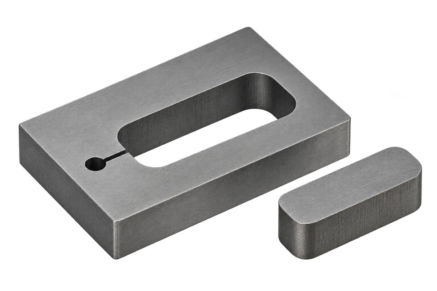
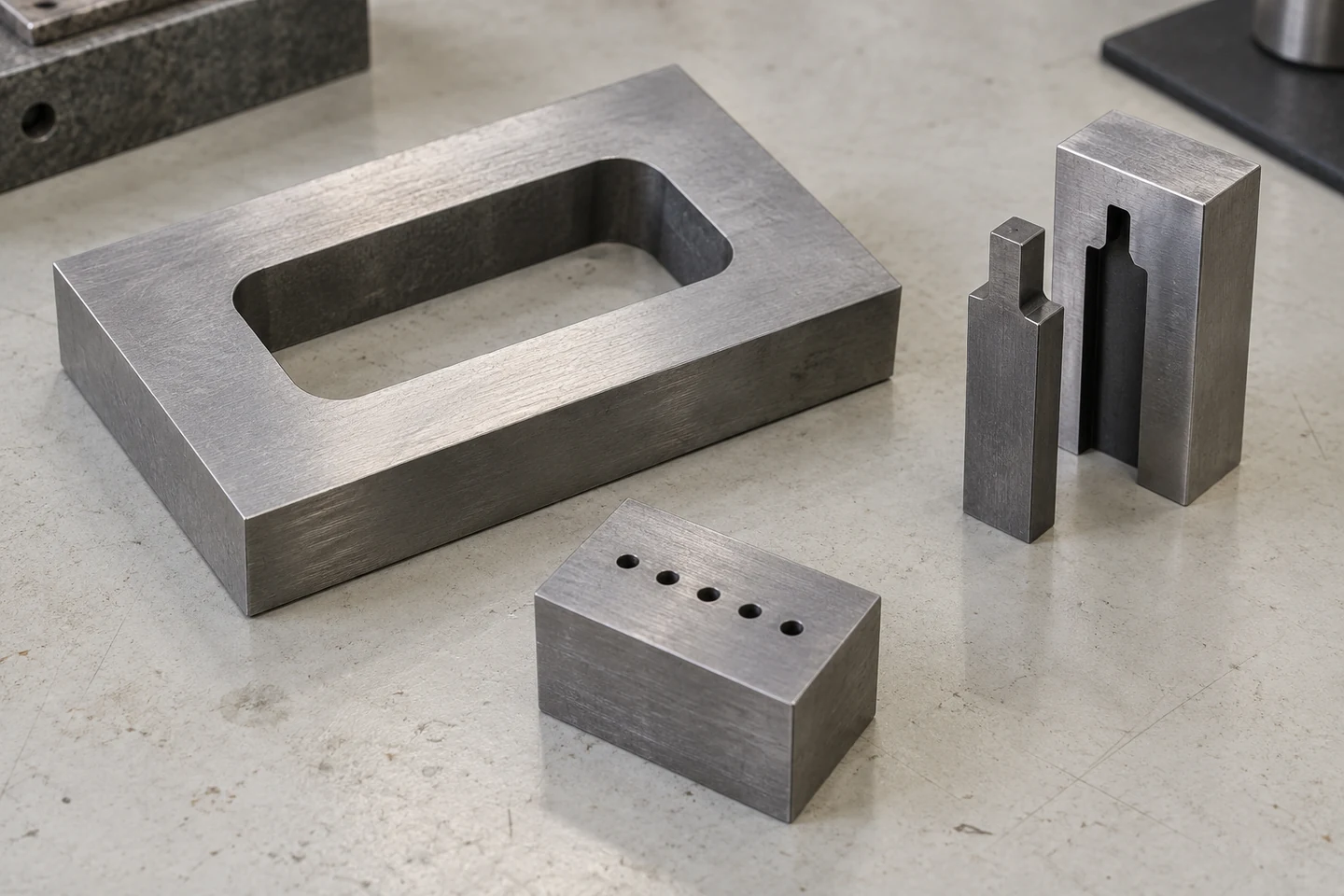
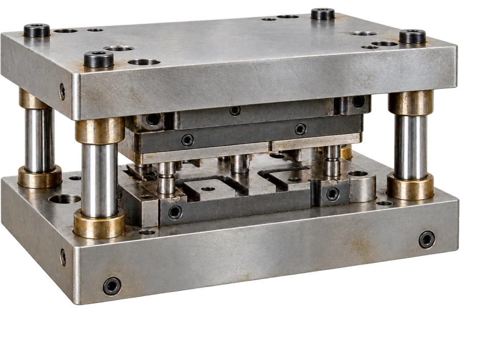
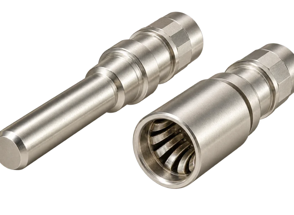
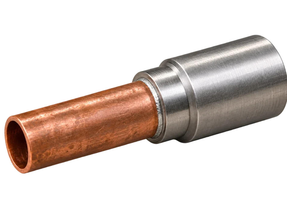
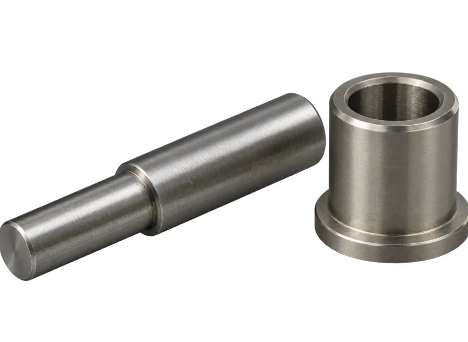
와이어컷 윤곽 부품과 소경 홀 가공품
전극과 진입 경로
관통 윤곽과 소경 홀은 다른 전극 운동으로 만들어집니다.
방전가공은 전도성 소재와 전극 사이의 간극에서 반복 방전을 일으켜 재료를 제거합니다. 열처리된 단단한 소재에도 적용할 수 있지만 전기·열적 특성과 가공액에 맞는 조건이 필요합니다.
와이어컷은 상하 가이드 사이를 이동하는 전극으로 관통 윤곽을 만듭니다. 폐쇄된 내측 형상에는 결선용 홀이 필요하며, 바닥이 남는 블라인드 포켓을 만드는 공정과 구분합니다.
소경 홀 방전가공은 회전 관 전극과 내부 가공액 공급을 이용합니다. 와이어 진입용 홀과 최종 기능 홀의 요구를 나누고, 홀의 목적에 따라 장비와 후속 마감을 선정합니다.
관통 윤곽·슬롯 · 상하 접근과 결선 경로
회전 관 전극 · 관통·블라인드 및 출구 조건
성형 전극의 공동 · 바닥 형상과 접근 검토
| 검토 항목 | 기술적 의미 | 검증·관리 기준 |
|---|---|---|
| 와이어컷 | 관통 윤곽·슬롯 | 상하 접근과 결선 경로 |
| 소경 홀 EDM | 회전 관 전극 | 관통·블라인드 및 출구 조건 |
| 형조 방전 | 성형 전극의 공동 | 바닥 형상과 접근 검토 |
와이어컷
기술적 의미
관통 윤곽·슬롯
검증·관리 기준
상하 접근과 결선 경로
소경 홀 EDM
기술적 의미
회전 관 전극
검증·관리 기준
관통·블라인드 및 출구 조건
형조 방전
기술적 의미
성형 전극의 공동
검증·관리 기준
바닥 형상과 접근 검토
진입 통로가 완성 윤곽의 기준을 자동으로 정하지는 않습니다.
스타트 홀은 와이어 결선과 진입 경로에 필요한 공간입니다. 최종 윤곽의 좌표는 도면 데이텀과 장비 셋업에서 설정하므로, 단순 결선용 홀을 곧바로 기능 기준으로 사용하지 않습니다.
홀은 대개 제거할 영역에 배치하고 완성면의 진입 흔적을 검토합니다. 결선 여유에는 실제 소재 두께, 홀의 기울기와 전극 편심, 노즐 접근성이 함께 영향을 줍니다.
홀이 부품에 남는 경우에는 위치·직경·출구 상태가 독립적인 검사 대상입니다. 절단 중 사라지는 홀은 불필요한 정밀 공차보다 결선성과 완성 윤곽의 보호를 우선합니다.
완성 윤곽의 위치 · 도면 데이텀·셋업 원점
홀에서 윤곽으로 이동 · 기능면 흔적과 제거 영역
결선에 필요한 통로 · 입출구 접근과 기울기
진입 통로가 완성 윤곽의 기준을 자동으로 정하지는 않습니다.
완성 윤곽의 위치 · 도면 데이텀·셋업 원점
| 검토 항목 | 기술적 의미 | 검증·관리 기준 |
|---|---|---|
| 기준 좌표 | 완성 윤곽의 위치 | 도면 데이텀·셋업 원점 |
| 진입선 | 홀에서 윤곽으로 이동 | 기능면 흔적과 제거 영역 |
| 관통 상태 | 결선에 필요한 통로 | 입출구 접근과 기울기 |
기준 좌표
기술적 의미
완성 윤곽의 위치
검증·관리 기준
도면 데이텀·셋업 원점
진입선
기술적 의미
홀에서 윤곽으로 이동
검증·관리 기준
기능면 흔적과 제거 영역
관통 상태
기술적 의미
결선에 필요한 통로
검증·관리 기준
입출구 접근과 기울기
소재와 가공 시스템
같은 경도라도 동일한 방전 조건을 쓰지는 않습니다.
열처리강, 스테인리스강, 니켈합금과 초경합금은 서로 다른 전기·열적 반응을 보입니다. 재종, 열처리 상태와 두께를 셋업 기록에 연결해야 조건 변화의 원인을 추적할 수 있습니다.
초경합금에는 WC 입자와 금속 결합상이 함께 존재합니다. 수계 가공액에서의 전기화학적 반응과 열적 손상을 검토하고 해당 재종에 맞는 방전·후처리 조건을 적용합니다.
소재 변경 승인은 치수 비교만으로 끝내지 않습니다. 기능면의 조도와 표면층, 모서리 손상, 세정·보관 조건까지 확인해 변경 후에도 기능 요구가 유지되는지 판단합니다.
전기·열적 반응 · 조건표와 재질 식별
응력·치수 변화 · 가공 전후 기준 비교
부식·열손상 민감도 · 가공액·마감 조건
전기·열적 반응 · 조건표와 재질 식별
| 검토 항목 | 기술적 의미 | 검증·관리 기준 |
|---|---|---|
| 재종 | 전기·열적 반응 | 조건표와 재질 식별 |
| 열처리 상태 | 응력·치수 변화 | 가공 전후 기준 비교 |
| 초경 결합상 | 부식·열손상 민감도 | 가공액·마감 조건 |
| 공급 로트 | 변동의 추적 | 성적서와 공정 이력 |
재종
기술적 의미
전기·열적 반응
검증·관리 기준
조건표와 재질 식별
열처리 상태
기술적 의미
응력·치수 변화
검증·관리 기준
가공 전후 기준 비교
초경 결합상
기술적 의미
부식·열손상 민감도
검증·관리 기준
가공액·마감 조건
공급 로트
기술적 의미
변동의 추적
검증·관리 기준
성적서와 공정 이력
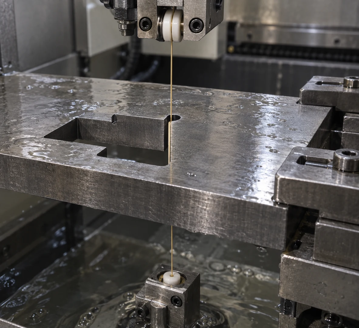
상하 가이드 사이의 연속 와이어와 가공부
04 / 04
플러싱은 배출과 와이어 안정성 사이의 균형입니다.
와이어는 전극이면서 장력을 받는 유연한 선입니다. 직경·재질·공급 상태·장력과 함께 상하 가이드 및 급전부의 오염과 마모를 관리해야 안정적인 절단이 가능합니다.
가공액은 부산물과 열을 운반하고 방전 간극의 전기적 상태를 유지합니다. 압력을 높이는 한 가지 조치보다 노즐 간격, 상하 유동과 형상 개방 정도의 조합이 중요합니다.
깊은 슬롯이나 소재 높이가 바뀌는 구간에서는 배출 조건이 달라집니다. 단선·경보·시간 변동을 경로 위치와 함께 기록하면 와이어 계통과 배출 문제를 구분하는 데 도움이 됩니다.
플러싱은 배출과 와이어 안정성 사이의 균형입니다.
| 검토 항목 | 기술적 의미 | 검증·관리 기준 |
|---|---|---|
| 와이어 | 유연한 전극 | 직경·장력·급전 |
| 가이드 | 전극 위치 구속 | 정렬·마모·청정도 |
| 노즐 | 국부 배출 | 간격·분사 균형 |
| 가공액 | 전기·열적 환경 | 여과·전도도·온도 |
와이어
기술적 의미
유연한 전극
검증·관리 기준
직경·장력·급전
가이드
기술적 의미
전극 위치 구속
검증·관리 기준
정렬·마모·청정도
노즐
기술적 의미
국부 배출
검증·관리 기준
간격·분사 균형
가공액
기술적 의미
전기·열적 환경
검증·관리 기준
여과·전도도·온도
윤곽 둘레에 간극을 만들고 후방 탭으로 슬러그를 지지합니다. 연속 와이어가 소재와 접촉하지 않는 위치를 확인합니다.
윤곽과 마감
상면 윤곽만으로 전체 벽면을 승인하지 않습니다.
내측 코너는 와이어 반지름과 방전 간극의 제약을 받습니다. 프로그램의 꼭짓점이 완전한 직각 공동이 된다고 가정하지 말고 상대 부품의 모서리와 조립 여유를 함께 검토합니다.
이송 방향이 바뀌면 와이어 지연과 굽힘이 코너 오차로 나타날 수 있습니다. 두꺼운 부품은 상·하면뿐 아니라 중앙부의 배부름이나 잘록함까지 확인해야 관통 맞춤을 판단할 수 있습니다.
코너 감속, 보정값과 스킴컷 순서는 측정된 오차에 맞춰 조정합니다. 장력을 높이는 단일 처방 대신 초기 절단의 안정성과 취약 형상별 조건을 함께 검토합니다.
전극·간극 제약 · 상대 모서리 간섭
테이퍼·수직도 · 동일 기준의 두 높이
와이어 굽힘 흔적 · 중간 단면 형상
전극·간극 제약 · 상대 모서리 간섭
| 검토 항목 | 기술적 의미 | 검증·관리 기준 |
|---|---|---|
| 내측 R | 전극·간극 제약 | 상대 모서리 간섭 |
| 상하 윤곽 | 테이퍼·수직도 | 동일 기준의 두 높이 |
| 중앙부 | 와이어 굽힘 흔적 | 중간 단면 형상 |
| 코너 이송 | 지연·방전 변화 | 형상별 감속·마감 |
내측 R
기술적 의미
전극·간극 제약
검증·관리 기준
상대 모서리 간섭
상하 윤곽
기술적 의미
테이퍼·수직도
검증·관리 기준
동일 기준의 두 높이
중앙부
기술적 의미
와이어 굽힘 흔적
검증·관리 기준
중간 단면 형상
코너 이송
기술적 의미
지연·방전 변화
검증·관리 기준
형상별 감속·마감
첫 절단의 오차가 마감의 가능성을 제한합니다.
러프컷은 윤곽을 분리하며 마감할 재료를 남깁니다. 초기 절단에서 큰 굽힘이나 코너 오차가 생기면 가벼운 스킴컷을 반복해도 효율적으로 보정하기 어려울 수 있습니다.
스킴컷은 작은 제거량과 낮은 방전 에너지로 치수와 표면을 다듬습니다. 패스 수만으로 재용융층 제거를 보증하지 않고 소재·발생기 조건·극성·오프셋의 조합을 검증합니다.
적층 제조 Ti6Al4V의 실험에서는 여러 마감 패스와 에너지 조절로 조도와 균열 양상이 개선되었지만 전극 성분 전이도 관찰되었습니다. 이를 다른 강재나 초경의 보편적인 패스 수 또는 합격 조건으로 전용하지 않습니다.
윤곽·마감 여유 · 초기 벽면 오차 억제
작은 제거량 · 패스별 조건·보정 기록
표면층·전극 전이 · 재료별 단면 확인
윤곽·마감 여유 · 초기 벽면 오차 억제
| 검토 항목 | 기술적 의미 | 검증·관리 기준 |
|---|---|---|
| 러프컷 | 윤곽·마감 여유 | 초기 벽면 오차 억제 |
| 스킴컷 | 작은 제거량 | 패스별 조건·보정 기록 |
| 극성·에너지 | 표면층·전극 전이 | 재료별 단면 확인 |
| 공정 승인 | 전체 경로 재현성 | 대표·취약 형상 검증 |
러프컷
기술적 의미
윤곽·마감 여유
검증·관리 기준
초기 벽면 오차 억제
스킴컷
기술적 의미
작은 제거량
검증·관리 기준
패스별 조건·보정 기록
극성·에너지
기술적 의미
표면층·전극 전이
검증·관리 기준
재료별 단면 확인
공정 승인
기술적 의미
전체 경로 재현성
검증·관리 기준
대표·취약 형상 검증
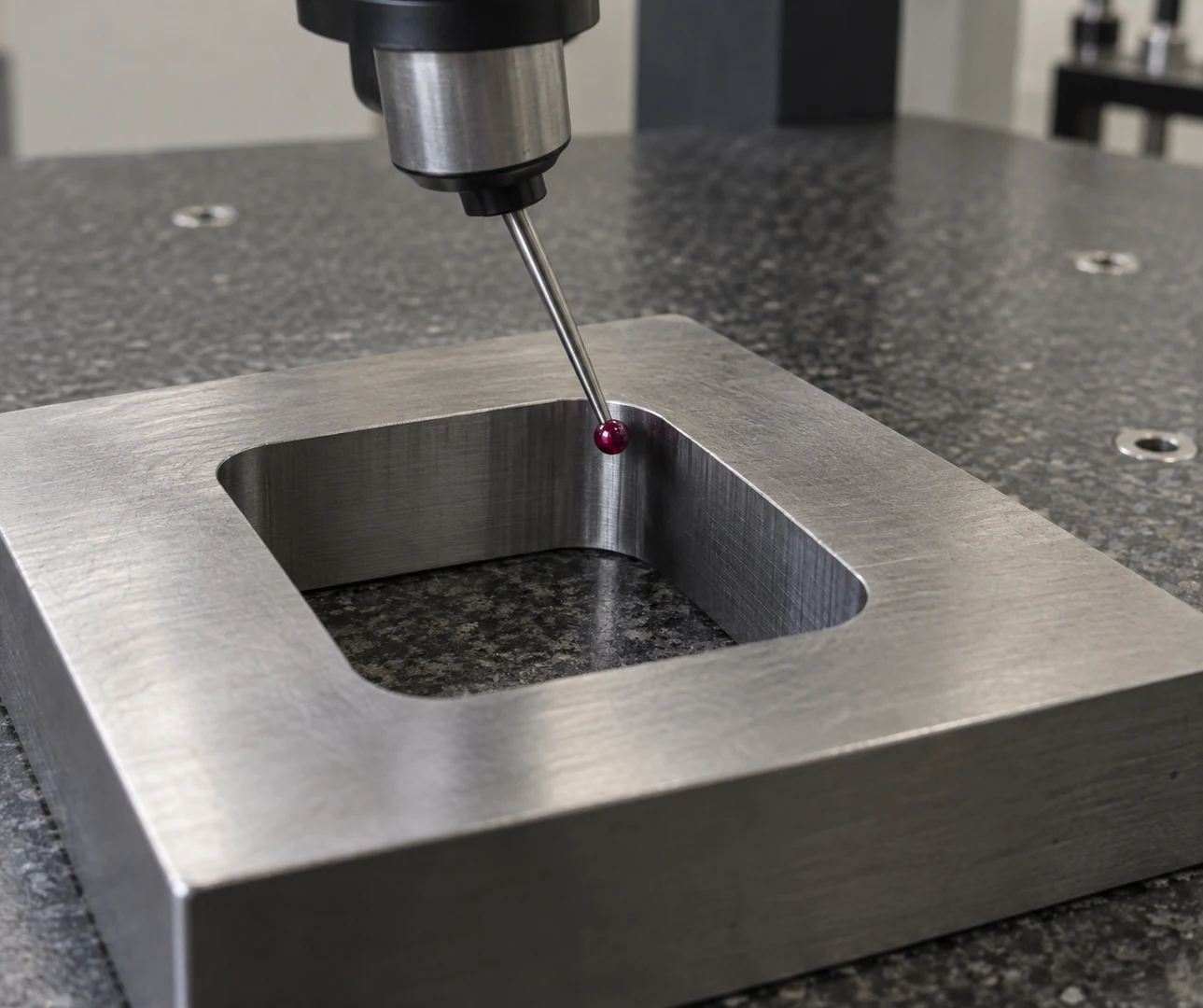
내측 윤곽 벽면의 좌표 측정 구성
홀 제어와 보정
기능 홀에는 입구 밖의 정보도 필요합니다.
관 전극은 가공 중 소모되어 길이와 끝단 상태가 바뀝니다. 홀 깊이·직경·기울기에 맞는 마모 보정과 내부 플러싱을 적용하고 전극 교환 기준을 정합니다.
관통 직전과 직후에는 방전 및 유동 조건이 달라집니다. 중공 부품에서는 관통 후 전극이 반대벽을 손상시키지 않도록 정지 검출과 여유 공간을 검토합니다.
입출구 직경, 테이퍼, 축 방향과 출구 가장자리 상태를 함께 검사합니다. 냉각·유량을 담당하는 홀에는 기하 검사 외의 기능 요구도 적용하며 결선용 홀의 합격을 그대로 사용하지 않습니다.
길이·끝단 변화 · 보정·교환 기준
출구 이후 방전 · 정지 응답·반대벽 여유
깊이별 크기 차이 · 복수 높이 측정
기능 홀에는 입구 밖의 정보도 필요합니다.
길이·끝단 변화 · 보정·교환 기준
| 검토 항목 | 기술적 의미 | 검증·관리 기준 |
|---|---|---|
| 전극 마모 | 길이·끝단 변화 | 보정·교환 기준 |
| 관통 검출 | 출구 이후 방전 | 정지 응답·반대벽 여유 |
| 테이퍼 | 깊이별 크기 차이 | 복수 높이 측정 |
| 기능 | 유량·조립 요구 | 최종 용도의 시험 |
전극 마모
기술적 의미
길이·끝단 변화
검증·관리 기준
보정·교환 기준
관통 검출
기술적 의미
출구 이후 방전
검증·관리 기준
정지 응답·반대벽 여유
테이퍼
기술적 의미
깊이별 크기 차이
검증·관리 기준
복수 높이 측정
기능
기술적 의미
유량·조립 요구
검증·관리 기준
최종 용도의 시험
전극이 열린 출구를 지나며 관통합니다. 실제 공정에서는 관통 검출과 반대벽 보호를 별도로 관리합니다.
단순 기하식은 시험 절단을 해석하는 출발점입니다.
직선 절단의 양쪽 간극이 같다고 가정하면 커프 폭은 와이어 직경과 두 간극의 합으로 근사할 수 있습니다. 실제 장비의 보정에는 패스별 제거량과 제어 방식도 반영됩니다.
내부·외부 윤곽은 보정 방향이 반대이므로 공구 중심 경로와 완성면을 구분합니다. 코너, 테이퍼와 높이 변화는 직선 시험편에서 얻은 값을 전용하기 전에 따로 확인합니다.
아래 계산은 장비 설정을 지시하지 않는 설명용 예입니다. 동일한 소재·두께·와이어·가공액으로 시험 절단하고 상하 및 중앙 치수를 확인한 뒤 실제 보정값을 확정합니다.
k: 직선 커프 폭[mm], d: 와이어 직경[mm], g: 일정하다고 가정한 편측 간극[mm], O: 완성 직선면에서 와이어 중심까지의 기하 거리[mm]. d=0.25 mm, g=0.020 mm이면 k≈0.290 mm, O≈0.145 mm입니다. 양측 간극이 대칭이고 추가 마감 여유가 없는 조건부 예이며 실제 CAM 오프셋·코너 보정·정밀도 보증값이 아닙니다.
전극의 실제 크기 · 사용 와이어 확인
| 검토 항목 | 기술적 의미 | 검증·관리 기준 |
|---|---|---|
| 와이어 d | 전극의 실제 크기 | 사용 와이어 확인 |
| 간극 g | 편측 방전 여유 | 동일 조건 시험편 |
| 커프 k | 제거된 전체 폭 | 상하·중앙 비교 |
| 보정 방향 | 내·외측 구분 | CAM과 완성면 대조 |
와이어 d
기술적 의미
전극의 실제 크기
검증·관리 기준
사용 와이어 확인
간극 g
기술적 의미
편측 방전 여유
검증·관리 기준
동일 조건 시험편
커프 k
기술적 의미
제거된 전체 폭
검증·관리 기준
상하·중앙 비교
보정 방향
기술적 의미
내·외측 구분
검증·관리 기준
CAM과 완성면 대조
표면과 분리 안정성
매끄러운 표면에도 열적·화학적 변화가 남을 수 있습니다.
방전으로 녹은 재료가 모두 배출되지 않고 굳으면 재용융층이 생깁니다. 그 아래 열영향부는 같은 개념이 아니며 조직과 균열 양상은 재료와 방전 이력에 따라 달라집니다.
조도는 표면 높이의 변화를 나타내지만 균열 깊이나 변질층의 성분을 직접 보여 주지 않습니다. 피로·밀봉·미끄럼 기능이 중요한 면은 필요에 따라 단면과 표면 결함을 추가 확인합니다.
폴리싱과 래핑은 표면층과 함께 치수·모서리도 바꿉니다. 허용층과 최종 치수의 검사 시점을 정하고 후처리 이전의 결과만으로 완성 부품을 승인하지 않습니다.
매끄러운 표면에도 열적·화학적 변화가 남을 수 있습니다.
재응고한 재료 · 단면·연속성
| 검토 항목 | 기술적 의미 | 검증·관리 기준 |
|---|---|---|
| 재용융층 | 재응고한 재료 | 단면·연속성 |
| 열영향부 | 하부 조직 변화 | 재질별 조직·경도 |
| 균열 | 국부 손상 경로 | 기능 위험별 관찰 |
| 후처리 | 층·치수 변화 | 최종 벽면·모서리 |
재용융층
기술적 의미
재응고한 재료
검증·관리 기준
단면·연속성
열영향부
기술적 의미
하부 조직 변화
검증·관리 기준
재질별 조직·경도
균열
기술적 의미
국부 손상 경로
검증·관리 기준
기능 위험별 관찰
후처리
기술적 의미
층·치수 변화
검증·관리 기준
최종 벽면·모서리
마지막 절단 이후의 움직임도 공정의 일부입니다.
폐쇄 윤곽의 마지막 연결부가 끊어지면 슬러그가 이동하거나 떨어질 수 있습니다. 와이어 물림과 완성면 스크래치를 막도록 지지·회수 방식과 마지막 절단 위치를 정합니다.
절단은 잔류응력의 구속을 해방하여 형상을 바꿀 수 있습니다. 얇은 리브나 비대칭 부품은 고정 상태와 분리 후 자유 상태의 치수가 다를 수 있어 검사 조건을 통일해야 합니다.
탭 유지나 단계별 절단이 필요하면 잔여 흔적의 제거까지 계획합니다. 절단 시간만 줄이고 회수·수정 시간이 늘어나는 공정은 전체 생산성 관점에서 다시 검토합니다.
분리 직후 이동 · 지지·회수 순서
구속 해방 변형 · 분리 후 치수
안정성과 잔여 흔적 · 위치·제거·마감
분리 직후 이동 · 지지·회수 순서
| 검토 항목 | 기술적 의미 | 검증·관리 기준 |
|---|---|---|
| 슬러그 | 분리 직후 이동 | 지지·회수 순서 |
| 잔류응력 | 구속 해방 변형 | 분리 후 치수 |
| 유지 탭 | 안정성과 잔여 흔적 | 위치·제거·마감 |
| 재고정 | 데이텀 이동 | 기준 재현과 이력 |
슬러그
기술적 의미
분리 직후 이동
검증·관리 기준
지지·회수 순서
잔류응력
기술적 의미
구속 해방 변형
검증·관리 기준
분리 후 치수
유지 탭
기술적 의미
안정성과 잔여 흔적
검증·관리 기준
위치·제거·마감
재고정
기술적 의미
데이텀 이동
검증·관리 기준
기준 재현과 이력
측정과 생산 준비
크기·위치·표면은 서로 다른 증거입니다.
윤곽 측정은 기능 데이텀에서 시작합니다. CMM이나 광학 측정의 평가 높이와 점 배치를 정해야 코너·직선·두께 방향의 오차를 일관되게 비교할 수 있습니다.
핀 게이지는 통과 여부를 알려 주지만 위치나 상세 원통도를 모두 설명하지 않습니다. 작은 내측 면의 조도 측정에서는 접근, 측정 방향과 평가 길이의 한계도 확인합니다.
검사 결과는 원인 조치로 연결합니다. 위치 오차는 셋업과 좌표, 일정한 크기 편차는 보정, 국부 표면 이상은 방전·배출 조건으로 되돌려 검토합니다.
데이텀과 관계 · 기준·평가 높이
기능 크기 · 위치·형상 측정 보완
높이 변화 · 방향·길이·접근
크기·위치·표면은 서로 다른 증거입니다.
데이텀과 관계 · 기준·평가 높이
| 검토 항목 | 기술적 의미 | 검증·관리 기준 |
|---|---|---|
| 윤곽 위치 | 데이텀과 관계 | 기준·평가 높이 |
| 통과 게이지 | 기능 크기 | 위치·형상 측정 보완 |
| 표면조도 | 높이 변화 | 방향·길이·접근 |
| 단면 | 표면층의 증거 | 위치·시편 준비 기록 |
윤곽 위치
기술적 의미
데이텀과 관계
검증·관리 기준
기준·평가 높이
통과 게이지
기술적 의미
기능 크기
검증·관리 기준
위치·형상 측정 보완
표면조도
기술적 의미
높이 변화
검증·관리 기준
방향·길이·접근
단면
기술적 의미
표면층의 증거
검증·관리 기준
위치·시편 준비 기록
필요한 기능을 공정 변수와 검사로 번역합니다.
도면 검토에는 소재·열처리·두께, 데이텀과 관통 여부, 최소 내측 R을 함께 제시합니다. 표면층 요구는 조도와 분리해 대상 면과 확인 방법을 명시합니다.
와이어·전극, 러프·스킴 경로, 가공액, 슬러그 처리와 검사 결과를 공정 기록으로 연결합니다. 소모품이나 소재 변경 뒤에는 영향을 받는 특성을 중심으로 재확인합니다.
좋은 방전가공 기준은 가장 작은 수치를 나열하는 방식이 아닙니다. 기능을 해치는 오차와 그 원인, 측정 방법을 연결해야 복잡한 형상에서도 재현 가능한 품질이 만들어집니다.
기능·가공 범위 · 재질·기준·R·관통
조건 재현 · 전극·경로·가공액
최종 상태 판정 · 치수·표면·후처리
기능·가공 범위 · 재질·기준·R·관통
| 검토 항목 | 기술적 의미 | 검증·관리 기준 |
|---|---|---|
| 도면 | 기능·가공 범위 | 재질·기준·R·관통 |
| 공정 기록 | 조건 재현 | 전극·경로·가공액 |
| 검사 합의 | 최종 상태 판정 | 치수·표면·후처리 |
| 변경 관리 | 조건 이동 | 영향 특성 재검증 |
도면
기술적 의미
기능·가공 범위
검증·관리 기준
재질·기준·R·관통
공정 기록
기술적 의미
조건 재현
검증·관리 기준
전극·경로·가공액
검사 합의
기술적 의미
최종 상태 판정
검증·관리 기준
치수·표면·후처리
변경 관리
기술적 의미
조건 이동
검증·관리 기준
영향 특성 재검증
소재·두께·열처리, 기능 기준면과 홀·윤곽 도면을 함께 전달해 주세요.
Share material, thickness, condition, datums and drawings of holes and profiles.
ELECTRICAL DISCHARGE MACHINING
Explore the continuous wire path and the drilling and breakthrough sequence of a tubular electrode.
Wire · Tube electrode · Gap · Altered layer
ENGLISH EDITION
Design electrode paths together with finished surfaces
Precise profiles require more than programmed coordinates. Electrode access, discharge gaps and final surface condition must work together.
Connect start holes, kerf compensation, skim cuts, surface integrity and inspection into a complete wire and small-hole EDM process.
Wire-cut profiles and small-hole components
Electrodes and access
Through profiles and small holes need different electrode motions.
EDM removes material through repeated discharges across a gap between an electrode and a conductive workpiece. It can process hardened stock, but its settings must suit the electrical, thermal and dielectric conditions.
Wire EDM creates through profiles with a travelling electrode between upper and lower guides. Closed internal contours need a threading hole; this is distinct from making a blind pocket that retains its floor.
Small-hole EDM uses a rotating tubular electrode and internal dielectric delivery. Separate holes for wire access from final functional holes, then choose equipment and subsequent finishing for their intended purpose.
Through contours and slots. Guide access and threading route
Rotating tubular electrode. Through, blind and exit conditions
Shaped-electrode cavity. Floor geometry and access
| Review item | Engineering significance | Verification or control |
|---|---|---|
| Wire EDM | Through contours and slots | Guide access and threading route |
| Hole EDM | Rotating tubular electrode | Through, blind and exit conditions |
| Sinker EDM | Shaped-electrode cavity | Floor geometry and access |
Wire EDM
Engineering significance
Through contours and slots
Verification or control
Guide access and threading route
Hole EDM
Engineering significance
Rotating tubular electrode
Verification or control
Through, blind and exit conditions
Sinker EDM
Engineering significance
Shaped-electrode cavity
Verification or control
Floor geometry and access
Access does not automatically establish the finished contour datum.
A start hole provides space for threading and a lead-in path. The drawing datums and machine setup define final coordinates; a simple access hole is not automatically a functional datum.
Place the hole in removable material where appropriate and review the lead-in witness on the finished wall. Threading clearance depends on stock thickness, hole inclination, electrode eccentricity and nozzle access.
If the hole remains in the component, its position, size and exit condition require independent inspection. For a hole removed during cutting, prioritize threading reliability and finished-contour protection over unnecessary precision.
Finished contour position. Drawing datums and setup origin
Travel from hole to contour. Witness marks and removable region
Threading access. Entrance, exit and inclination
Access does not automatically establish the finished contour datum.
Finished contour position. Drawing datums and setup origin
| Review item | Engineering significance | Verification or control |
|---|---|---|
| Datum coordinates | Finished contour position | Drawing datums and setup origin |
| Lead-in | Travel from hole to contour | Witness marks and removable region |
| Breakthrough | Threading access | Entrance, exit and inclination |
Datum coordinates
Engineering significance
Finished contour position
Verification or control
Drawing datums and setup origin
Lead-in
Engineering significance
Travel from hole to contour
Verification or control
Witness marks and removable region
Breakthrough
Engineering significance
Threading access
Verification or control
Entrance, exit and inclination
Materials and machining systems
Equal hardness does not justify identical EDM settings.
Hardened steel, stainless steel, nickel alloys and cemented carbide respond differently to electrical and thermal loading. Link grade, condition and thickness to setup records to trace process changes.
Cemented carbide contains WC grains and a metallic binder. Review electrochemical effects in water dielectric as well as thermal damage, and select grade-appropriate EDM and post-processing conditions.
Material-substitution approval requires more than matching dimensions. Review functional-surface texture, altered layers, edge damage, cleaning and storage to establish whether the functional requirements remain satisfied.
Electrical and thermal response. Identify material and technology settings
Stress and dimensional movement. Compare dimensions before and after
Corrosion and thermal sensitivity. Dielectric and finishing review
Electrical and thermal response. Identify material and technology settings
| Review item | Engineering significance | Verification or control |
|---|---|---|
| Grade | Electrical and thermal response | Identify material and technology settings |
| Condition | Stress and dimensional movement | Compare dimensions before and after |
| Carbide binder | Corrosion and thermal sensitivity | Dielectric and finishing review |
| Supply lot | Variation traceability | Certificates and process history |
Grade
Engineering significance
Electrical and thermal response
Verification or control
Identify material and technology settings
Condition
Engineering significance
Stress and dimensional movement
Verification or control
Compare dimensions before and after
Carbide binder
Engineering significance
Corrosion and thermal sensitivity
Verification or control
Dielectric and finishing review
Supply lot
Engineering significance
Variation traceability
Verification or control
Certificates and process history
Continuous wire between upper and lower guides
04 / 04
Flushing balances evacuation with wire stability.
The wire is an electrode and a flexible tensioned line. Stable cutting requires control of diameter, composition, feed and tension together with cleanliness and wear of guides and power contacts.
The dielectric transports debris and heat and maintains electrical conditions in the gap. Nozzle spacing, balanced flow and geometry openness matter more than a simple instruction to increase pressure.
Deep slots and changes in workpiece height change evacuation conditions. Record wire breaks, alarms and cycle-time shifts against contour location to help distinguish wire-system faults from flushing problems.
Flushing balances evacuation with wire stability.
| Review item | Engineering significance | Verification or control |
|---|---|---|
| Wire | Flexible electrode | Diameter, tension and power contact |
| Guides | Constrain position | Alignment, wear and cleanliness |
| Nozzles | Local evacuation | Spacing and balanced delivery |
| Dielectric | Electrical and thermal environment | Filtration, conductivity and temperature |
Wire
Engineering significance
Flexible electrode
Verification or control
Diameter, tension and power contact
Guides
Engineering significance
Constrain position
Verification or control
Alignment, wear and cleanliness
Nozzles
Engineering significance
Local evacuation
Verification or control
Spacing and balanced delivery
Dielectric
Engineering significance
Electrical and thermal environment
Verification or control
Filtration, conductivity and temperature
A rear tab retains the slug within the cut profile. The continuous wire remains clear of solid stock.
Contour and finishing
The top profile does not establish the entire wall geometry.
Internal corners are constrained by wire radius and discharge gap. A programmed vertex does not become a perfectly sharp cavity; review mating edges and assembly clearance together.
Changes in feed direction can turn wire lag and bow into corner error. Thick parts require checks for mid-thickness bulging or necking as well as top and bottom profiles before accepting a through fit.
Adjust corner feed, compensation and skim sequence to the measured error. Rather than treating higher tension as a universal correction, review first-cut stability and conditions for the sensitive geometry.
Electrode and gap constraint. Mating-edge interference
Taper and squareness. Two heights in one datum system
Evidence of wire bow. Intermediate profile
Electrode and gap constraint. Mating-edge interference
| Review item | Engineering significance | Verification or control |
|---|---|---|
| Inside radius | Electrode and gap constraint | Mating-edge interference |
| Top and bottom | Taper and squareness | Two heights in one datum system |
| Mid-thickness | Evidence of wire bow | Intermediate profile |
| Corner feed | Lag and discharge changes | Geometry-specific feed and finish |
Inside radius
Engineering significance
Electrode and gap constraint
Verification or control
Mating-edge interference
Top and bottom
Engineering significance
Taper and squareness
Verification or control
Two heights in one datum system
Mid-thickness
Engineering significance
Evidence of wire bow
Verification or control
Intermediate profile
Corner feed
Engineering significance
Lag and discharge changes
Verification or control
Geometry-specific feed and finish
First-cut errors constrain what finishing can correct.
The rough cut separates the contour and leaves finishing stock. Large bow or corner errors in that cut may be difficult to correct efficiently with repeated light skims.
Skim passes refine size and surface with small stock removal and lower discharge energy. Pass count alone does not guarantee recast removal; validate material, generator conditions, polarity and offsets together.
Experiments on additively manufactured Ti6Al4V improved texture and crack observations using multiple finishing passes and energy control, but also detected electrode-element transfer. The results do not prescribe universal pass counts or acceptance conditions for steels or carbides.
Contour and finishing stock. Limit initial wall error
Small stock removal. Record settings and offsets by pass
Layers and electrode transfer. Material-specific section review
Contour and finishing stock. Limit initial wall error
| Review item | Engineering significance | Verification or control |
|---|---|---|
| Rough cut | Contour and finishing stock | Limit initial wall error |
| Skim cut | Small stock removal | Record settings and offsets by pass |
| Polarity and energy | Layers and electrode transfer | Material-specific section review |
| Process release | Full-path repeatability | Validate representative and sensitive features |
Rough cut
Engineering significance
Contour and finishing stock
Verification or control
Limit initial wall error
Skim cut
Engineering significance
Small stock removal
Verification or control
Record settings and offsets by pass
Polarity and energy
Engineering significance
Layers and electrode transfer
Verification or control
Material-specific section review
Process release
Engineering significance
Full-path repeatability
Verification or control
Validate representative and sensitive features
Coordinate measurement setup for an internal wall
Hole control and compensation
Functional holes require information beyond the entrance.
A tubular electrode loses length and changes tip condition during drilling. Apply wear compensation and internal flushing for the hole depth, diameter and inclination, and establish replacement criteria.
Discharge and flow conditions change near breakthrough. For hollow components, review stopping detection and clearance so that continued drilling does not strike the opposite wall.
Inspect entrance and exit size, taper, axis direction and exit edges together. Cooling or flow holes also need verification against their functional requirements, beyond criteria for a simple threading hole.
Length and tip changes. Compensation and replacement
Discharges beyond the exit. Stopping response and back-wall clearance
Size variation with depth. Multiple evaluation levels
Functional holes require information beyond the entrance.
Length and tip changes. Compensation and replacement
| Review item | Engineering significance | Verification or control |
|---|---|---|
| Electrode wear | Length and tip changes | Compensation and replacement |
| Breakthrough | Discharges beyond the exit | Stopping response and back-wall clearance |
| Taper | Size variation with depth | Multiple evaluation levels |
| Function | Flow or assembly duty | Application-specific tests |
Electrode wear
Engineering significance
Length and tip changes
Verification or control
Compensation and replacement
Breakthrough
Engineering significance
Discharges beyond the exit
Verification or control
Stopping response and back-wall clearance
Taper
Engineering significance
Size variation with depth
Verification or control
Multiple evaluation levels
Function
Engineering significance
Flow or assembly duty
Verification or control
Application-specific tests
The electrode passes an open exit. Actual machining requires breakthrough detection and back-wall protection.
A geometric estimate starts the interpretation of trial cuts.
For a straight cut with equal gaps on both sides, kerf width is approximately wire diameter plus two gaps. Actual machine compensation also includes pass-specific removal and controller conventions.
Internal and external contours require opposite compensation directions. Distinguish the wire centerline from the finished wall, and verify corners, taper and height transitions before transferring straight-coupon results.
The calculation below is illustrative, not a machine recipe. Trial-cut with matching material, thickness, wire and dielectric, then verify upper, lower and intermediate dimensions before establishing the offset.
k: straight kerf [mm]; d: wire diameter [mm]; g: assumed constant side gap [mm]; O: distance from the finished straight wall to the wire center [mm]. For d=0.25 mm and g=0.020 mm, k≈0.290 mm and O≈0.145 mm. This example assumes symmetric gaps and no additional finishing stock; it is not a prescribed CAM offset, corner correction or accuracy guarantee.
Electrode size. Confirm the actual wire
| Review item | Engineering significance | Verification or control |
|---|---|---|
| Wire d | Electrode size | Confirm the actual wire |
| Gap g | Side discharge clearance | Matching trial coupon |
| Kerf k | Total removed width | Compare top, bottom and middle |
| Offset direction | Inside versus outside | Compare CAM with finished wall |
Wire d
Engineering significance
Electrode size
Verification or control
Confirm the actual wire
Gap g
Engineering significance
Side discharge clearance
Verification or control
Matching trial coupon
Kerf k
Engineering significance
Total removed width
Verification or control
Compare top, bottom and middle
Offset direction
Engineering significance
Inside versus outside
Verification or control
Compare CAM with finished wall
Surface and separation stability
Smooth surfaces can retain thermal or chemical changes.
Molten material that is not expelled can resolidify into a recast layer. The heat-affected region below it is distinct, and microstructure and cracking depend on material and discharge history.
Roughness describes height variation but does not directly reveal crack depth or layer chemistry. Surfaces critical to fatigue, sealing or sliding may need section and defect examination as well.
Polishing and lapping alter dimensions and edges while removing layers. Define the permitted condition and final inspection stage; results before post-processing do not release the completed part.
Smooth surfaces can retain thermal or chemical changes.
Resolidified material. Section and continuity
| Review item | Engineering significance | Verification or control |
|---|---|---|
| Recast | Resolidified material | Section and continuity |
| Heat-affected region | Underlying structural change | Material-specific structure and hardness |
| Cracks | Local damage paths | Function-driven inspection |
| Post-processing | Layer and size changes | Final walls and edges |
Recast
Engineering significance
Resolidified material
Verification or control
Section and continuity
Heat-affected region
Engineering significance
Underlying structural change
Verification or control
Material-specific structure and hardness
Cracks
Engineering significance
Local damage paths
Verification or control
Function-driven inspection
Post-processing
Engineering significance
Layer and size changes
Verification or control
Final walls and edges
Motion after the last cut is part of the process.
The slug can move or drop when the final connection is cut. Define support, retrieval and separation location to avoid trapped wire and scratches on finished walls.
Cutting can release residual stress and change geometry. Thin ribs and asymmetric parts may differ while restrained and after release, so use a consistent inspection condition.
If retention tabs or staged cuts are required, plan witness removal too. A shorter cut with longer retrieval and corrective work should be reassessed against total production time.
Movement after separation. Support and retrieval sequence
Released distortion. Unrestrained dimensions
Stability and witnesses. Location, removal and finishing
Movement after separation. Support and retrieval sequence
| Review item | Engineering significance | Verification or control |
|---|---|---|
| Slug | Movement after separation | Support and retrieval sequence |
| Residual stress | Released distortion | Unrestrained dimensions |
| Tabs | Stability and witnesses | Location, removal and finishing |
| Refixturing | Datum transfer | Re-establishment and records |
Slug
Engineering significance
Movement after separation
Verification or control
Support and retrieval sequence
Residual stress
Engineering significance
Released distortion
Verification or control
Unrestrained dimensions
Tabs
Engineering significance
Stability and witnesses
Verification or control
Location, removal and finishing
Refixturing
Engineering significance
Datum transfer
Verification or control
Re-establishment and records
Inspection and production readiness
Size, position and surface condition are different evidence.
Contour inspection begins with functional datums. Define CMM or optical evaluation heights and sampling locations to compare corner, straight-wall and through-thickness errors consistently.
A pin gauge indicates passage but does not establish position or detailed cylindricity. For small internal surfaces, review access, direction and evaluation-length limits in roughness measurement.
Connect inspection to action: trace position errors to setup, consistent size bias to compensation, and local surface anomalies to discharge and evacuation conditions.
Relation to datums. Alignment and evaluation heights
Functional size. Supplement with position and form
Height variation. Direction, length and access
Size, position and surface condition are different evidence.
Relation to datums. Alignment and evaluation heights
| Review item | Engineering significance | Verification or control |
|---|---|---|
| Contour position | Relation to datums | Alignment and evaluation heights |
| Pass gauge | Functional size | Supplement with position and form |
| Roughness | Height variation | Direction, length and access |
| Section | Evidence of altered layers | Location and specimen preparation |
Contour position
Engineering significance
Relation to datums
Verification or control
Alignment and evaluation heights
Pass gauge
Engineering significance
Functional size
Verification or control
Supplement with position and form
Roughness
Engineering significance
Height variation
Verification or control
Direction, length and access
Section
Engineering significance
Evidence of altered layers
Verification or control
Location and specimen preparation
Translate function into process variables and inspection.
Provide material, condition, thickness, datums, through-feature requirements and minimum inside radii. State altered-layer requirements separately from roughness, identifying surfaces and verification methods.
Link wire and electrodes, rough and skim paths, dielectric, slug handling and inspection results in production records. Recheck affected characteristics following consumable or material changes.
A useful EDM specification does more than list small numbers. Connect errors that impair function to their causes and measurements to achieve repeatable quality on complex profiles.

Function and scope. Material, datums, radii and through features
Reproduce conditions. Electrodes, paths and dielectric
Accept the final state. Size, surface and finishing stage
Function and scope. Material, datums, radii and through features
| Review item | Engineering significance | Verification or control |
|---|---|---|
| Drawing | Function and scope | Material, datums, radii and through features |
| Records | Reproduce conditions | Electrodes, paths and dielectric |
| Inspection | Accept the final state | Size, surface and finishing stage |
| Changes | Shifts in conditions | Revalidate affected characteristics |
Drawing
Engineering significance
Function and scope
Verification or control
Material, datums, radii and through features
Records
Engineering significance
Reproduce conditions
Verification or control
Electrodes, paths and dielectric
Inspection
Engineering significance
Accept the final state
Verification or control
Size, surface and finishing stage
Changes
Engineering significance
Shifts in conditions
Verification or control
Revalidate affected characteristics
전극 접근과 안정적인 방전·배출, 기능 기준에 맞는 측정으로 방전가공의 품질을 관리합니다. 홀의 용도와 데이텀을 구분하고 치수와 표면 건전성을 함께 확인합니다.
01 / 관통 윤곽과 블라인드 공동을 구분합니다.
02 / 스타트 홀은 결선 통로이며 자동으로 최종 기준이 되지 않습니다.
03 / 재종·두께·와이어·가공액을 함께 기록합니다.
04 / 상하 및 두께 중앙의 형상을 평가합니다.
05 / 스킴컷 횟수만으로 표면층 제거를 보증하지 않습니다.
06 / 슬러그 지지와 분리 후 변형을 관리합니다.
07 / 후처리가 끝난 최종 치수와 표면을 검사합니다.
일반 와이어컷은 관통 윤곽을 만듭니다. 바닥이 필요한 공동은 형조 방전이나 다른 공정을 검토합니다.
제거될 결선용 홀인지 남는 기능 홀인지에 따라 다릅니다. 전자는 접근 여유, 후자는 도면의 기능 요구가 중요합니다.
방전 간극이 더해집니다. 동일 조건의 시험 절단으로 보정값을 정합니다.
조건과 잔여 재료가 맞아야 합니다. 실제 치수와 표면 개선을 확인합니다.
와이어와 고정 안정성도 영향을 받습니다. 노즐 접근과 형상에 맞춰 균형을 정합니다.
서로 다른 특성입니다. 기능상 중요하면 단면과 결함 검사를 추가합니다.
결합상과 전기화학적 반응이 다릅니다. 재종별 조건과 후속 마감을 검토합니다.
재질·열처리·두께·데이텀·최소 R·홀 용도와 표면·검사 요구입니다.
결선 통로와 유량·조립용 홀의 요구를 나눕니다.
조도·재용융층·균열을 기능에 연결합니다.
위치별 오차를 셋업·경로·마감 조건으로 되돌립니다.
와이어컷팅소경 홀 방전스타트 홀방전 간극커프 보정스킴컷와이어 지연플러싱재용융층표면 건전성윤곽 검사
Control EDM through electrode access, stable discharge and evacuation, and function-based measurement. Separate hole purpose from datums and verify geometry together with surface integrity.
01 / Separate through profiles from blind cavities.
02 / A start hole provides access, not an automatic final datum.
03 / Record grade, thickness, wire and dielectric together.
04 / Assess top, bottom and intermediate geometry.
05 / Skim count alone does not guarantee layer removal.
06 / Manage slug support and released distortion.
07 / Inspect final dimensions and surfaces after finishing.
Ordinary wire EDM makes through profiles. Review sinker EDM or another process where a floor must remain.
A removable access hole and a retained functional hole have different needs: reliable access for the former and drawing requirements for the latter.
Discharge gaps add to the width. Establish offsets using matching trial cuts.
Conditions and remaining stock must suit the strategy. Verify actual dimensional and surface improvement.
Wire and fixture stability are also affected. Balance pressure against nozzle access and geometry.
These are different characteristics. Add section and defect checks when function requires them.
Binder and electrochemical response differ. Review grade-specific settings and finishing.
Material, condition, thickness, datums, minimum radii, hole purpose, and surface and inspection requirements.
Separate threading access from flow and assembly duties.
Connect texture, recast and cracks to function.
Feed location-specific errors back into setup, paths and finishing.
wire EDMsmall-hole EDMstart holedischarge gapkerf compensationskim cutwire lagflushingrecast layersurface integritycontour inspection
연결 준비 중입니다. 현재 전화 연결을 이용하실 수 있습니다.