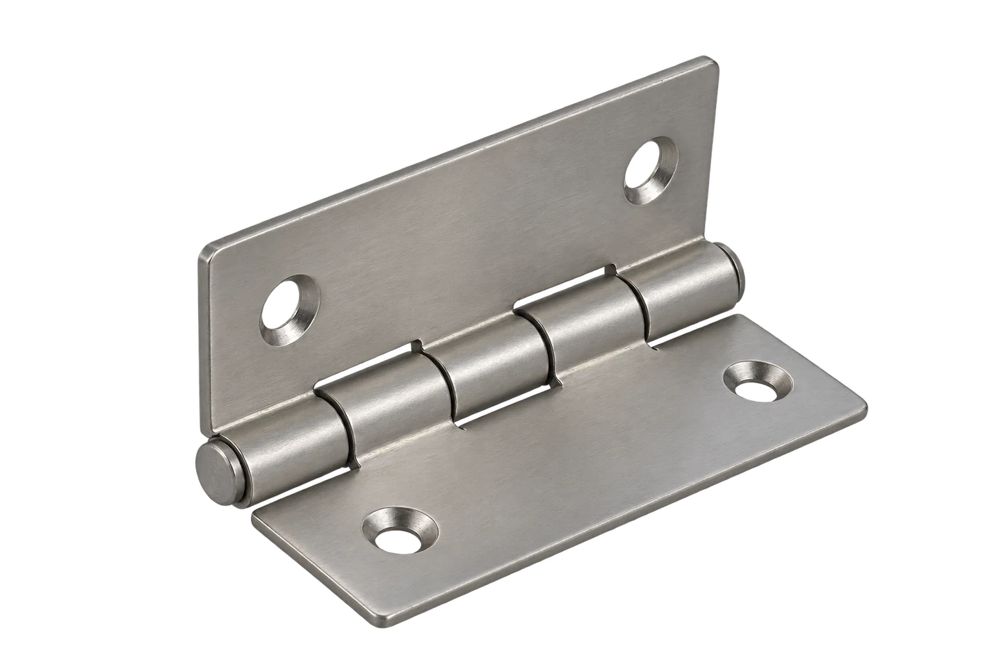
HINGE ASSEMBLY / 교대로 맞물리는 너클과 공통 핀

STAMPED HINGES

말림에서 회전으로.
힌지의 품질을 잇다.

너클 형상·핀 조립·완성 간극으로 검토하는 프레스 힌지

HINGE ASSEMBLY / 교대로 맞물리는 너클과 공통 핀

Form.
Align.
Rotate.

STAMPED HINGES

HINGE ASSEMBLY / 교대로 맞물리는 너클과 공통 핀

형상을 만들고.
움직임을 검증하다.

블랭크와 컬링 경로를 완성 상태의 간극, 조립력과 회전 수명으로 연결합니다.

CURL · ALIGNMENT · CLEARANCE · RETENTION

Overview.

정렬된 축과 유지되는 핀으로 반복 동작을 만듭니다.

힌지의 완성도는 너클이 둥글게 말렸는지보다, 조립한 뒤 필요한 하중에서 일정하게 움직이고 핀이 제자리에 남는지로 판단합니다.

얇은 판재의 절단면과 컬링 경로, 여러 너클의 동축도, 표면처리 후 간극과 핀 유지 구조를 하나의 치수 체계로 연결해야 합니다. 개발 단계의 시험 조건을 양산 검사와 이어 두면 뻑뻑함·유격·핀 이동을 서로 다른 원인으로 구분할 수 있습니다.

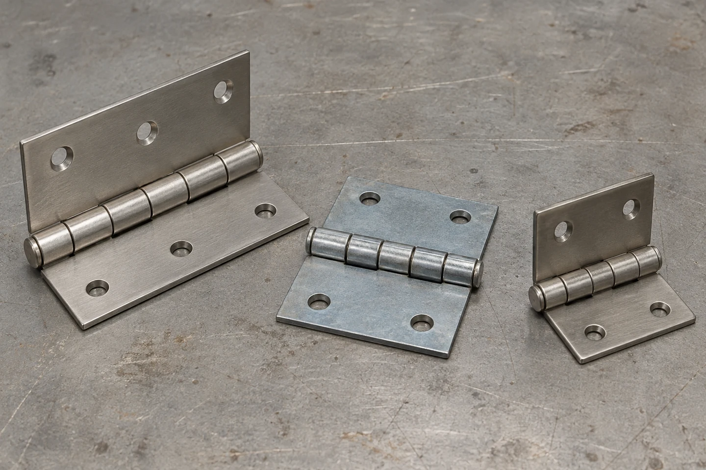
HINGE FAMILY / 크기와 표면이 다른 프레스 힌지

HINGE FAMILY / 크기와 표면이 다른 프레스 힌지

Structure.

기능과 너클 배열

01 / FUNCTIONAL INTENT

자유 회전과 위치 유지는 서로 다른 요구입니다

회전 저항·하중·개방 범위를 제품 사용 조건으로 정의합니다.

힌지는 두 판을 연결하면서 상대 회전을 허용하는 부품입니다. 먼저 문짝이나 커버의 질량, 무게중심과 설치 방향을 정하고, 사용자가 움직이는 힘과 필요한 개방 각도를 구분합니다. 같은 작은 힌지라도 수평 덮개와 수직 도어에서는 중력에 의한 모멘트와 핀의 축방향 하중이 달라지므로 외형 치수만으로 용도를 묶지 않습니다.

자유 회전형은 지정 하중에서 걸림 없이 움직이도록 하고, 위치 유지형은 정해진 회전 저항으로 자세를 유지하도록 설계합니다. 자유 회전용 너클의 구멍을 임의로 좁혀 마찰 힌지로 바꾸면 토크가 표면 상태와 마모에 민감해질 수 있습니다. 시작 토크와 운전 토크, 각도별 편차를 따로 정해야 요구 기능이 검사 항목으로 바뀝니다.

개방 끝에서 부딪히는 스토퍼와 잠금장치의 힘도 확인합니다. 힌지 너클이 우연히 맞닿는 위치를 정식 정지 구조로 간주하면 반복 충격이 말림부나 장착부에 집중될 수 있습니다. 사용 빈도와 진동, 오염·습기 및 정비 가능성을 함께 정의하고, 시험에서는 실제 부품을 지지하는 방향과 체결 조건을 재현합니다.

회전 기능

자유 회전 또는 위치 유지 · 시작·운전 토크 구분

사용 하중

중력·충격·축방향 힘 · 방향과 작용점 명시

개방 범위

회전과 정지 구조의 조합 · 각도별 간섭 확인

자유 회전과 위치 유지는 서로 다른 요구입니다 — 실무 판단 기준

검토 항목기술적 의미검증·관리 기준
회전 기능자유 회전 또는 위치 유지시작·운전 토크 구분
사용 하중중력·충격·축방향 힘방향과 작용점 명시
개방 범위회전과 정지 구조의 조합각도별 간섭 확인

회전 기능

기술적 의미
자유 회전 또는 위치 유지

검증·관리 기준
시작·운전 토크 구분

사용 하중

기술적 의미
중력·충격·축방향 힘

검증·관리 기준
방향과 작용점 명시

개방 범위

기술적 의미
회전과 정지 구조의 조합

검증·관리 기준
각도별 간섭 확인

02 / KNUCKLE ARCHITECTURE

너클 배열은 하중과 조립 기준을 함께 만듭니다

번갈아 맞물리는 구간과 실제 지지 길이를 구분합니다.

양쪽 리프의 너클은 축방향으로 번갈아 배치되어 하나의 핀을 공유합니다. 너클 수를 늘리는 것만으로 하중이 균등해지지는 않습니다. 각 구간의 직경·축선과 끝면 위치가 다르면 특정 너클이 먼저 접촉하므로, 전체 길이와 개별 너클 길이뿐 아니라 실제 맞물림 순서와 간격을 조립 도면에서 확인합니다.

너클 사이의 축방향 틈은 회전과 조립에 필요한 공간이지만 과도하면 핀의 지지되지 않는 구간이 길어집니다. 반대로 끝면이 눌리면 직경 간극이 충분해도 회전이 무거워집니다. 버·도막과 끝면 직각도까지 포함하여 최소 간극과 최대 흔들림을 함께 검토하고, 간극을 한쪽 끝에 몰아 둔 조립도 따로 평가합니다.

장착 구멍과 힌지 축의 관계는 커버 위치를 결정합니다. 리프 평면을 기준으로 너클 축의 높이와 평행도를 관리하고, 장착 구멍의 위치를 같은 기준에 연결합니다. 자유 상태에서 맞는 리프도 체결면이 휘었거나 나사 조임 순서가 달라지면 축선이 바뀔 수 있으므로 부품 검사와 장착 상태 검사를 구분하여 남깁니다.

너클 길이

실제 접촉·지지 구간 · 개별 길이와 배열 검사

축방향 틈

끝면 마찰과 핀 굽힘에 영향 · 최소·최대 조립 상태

장착 기준

리프와 축선의 위치 관계 · 체결 상태 재현

번갈아 맞물리는 구간과 실제 지지 길이를 구분합니다.

너클 길이

실제 접촉·지지 구간 · 개별 길이와 배열 검사

너클 배열은 하중과 조립 기준을 함께 만듭니다 — 실무 판단 기준

검토 항목기술적 의미검증·관리 기준
너클 길이실제 접촉·지지 구간개별 길이와 배열 검사
축방향 틈끝면 마찰과 핀 굽힘에 영향최소·최대 조립 상태
장착 기준리프와 축선의 위치 관계체결 상태 재현

너클 길이

기술적 의미
실제 접촉·지지 구간

검증·관리 기준
개별 길이와 배열 검사

축방향 틈

기술적 의미
끝면 마찰과 핀 굽힘에 영향

검증·관리 기준
최소·최대 조립 상태

장착 기준

기술적 의미
리프와 축선의 위치 관계

검증·관리 기준
체결 상태 재현

Materials.

소재와 블랭크 설계

03 / STOCK AND EDGES

소재 조질과 절단면이 컬링의 시작 조건입니다

강종 이름에 두께·방향·표면 상태를 더합니다.

판재의 항복·인장 거동과 두께는 필요한 성형력과 탄성 복원에 영향을 줍니다. 스테인리스, 저탄소강, 알루미늄을 같은 금형 깊이로 바꾸어 적용하지 않고 실제 조질과 공급 두께 범위를 확인합니다. 특히 작은 내경으로 말아야 하는 부분은 평판의 인장강도보다 국부 굽힘성과 절단 가장자리의 상태가 먼저 한계를 드러낼 수 있습니다.

압연 방향은 블랭크 배치와 연결하여 기록합니다. 소재에 따라 방향별 굽힘 반응이 다르므로 재료 이용률만 보고 네스팅 방향을 돌리면 이전 시험과 다른 조건이 됩니다. 방향 변경이 불가피하면 해당 로트의 시편으로 말림 균열과 복원량을 다시 확인하고, 공급사 굽힘 자료의 강종·두께·시험 방식이 실제 조건과 맞는지도 대조합니다.

타발 버와 미세한 모서리 손상은 컬링 중 늘어나는 면에서 균열의 출발점이 될 수 있습니다. 버 방향을 도면과 공정에 표시하고 필요한 디버링 수준을 정하되, 과도한 연마로 너클 폭이나 리프 기준면이 변하지 않게 합니다. 성형 전에 검사한 절단면과 성형 후의 균열 위치를 연결하면 소재 문제와 날 마모 문제를 구분하기 쉬워집니다.

재질·조질

성형력과 연성의 기초 · 공급 성적·로트 연결

두께 범위

말림 단면과 하중 변화 · 실측 최소·최대 시험

압연 방향

방향별 성형 반응 · 블랭크 방향 추적

재질·조질

성형력과 연성의 기초 · 공급 성적·로트 연결

소재 조질과 절단면이 컬링의 시작 조건입니다 — 실무 판단 기준

검토 항목기술적 의미검증·관리 기준
재질·조질성형력과 연성의 기초공급 성적·로트 연결
두께 범위말림 단면과 하중 변화실측 최소·최대 시험
압연 방향방향별 성형 반응블랭크 방향 추적
절단 가장자리균열과 버의 시작 조건성형 전후 위치 대조

재질·조질

기술적 의미
성형력과 연성의 기초

검증·관리 기준
공급 성적·로트 연결

두께 범위

기술적 의미
말림 단면과 하중 변화

검증·관리 기준
실측 최소·최대 시험

압연 방향

기술적 의미
방향별 성형 반응

검증·관리 기준
블랭크 방향 추적

절단 가장자리

기술적 의미
균열과 버의 시작 조건

검증·관리 기준
성형 전후 위치 대조

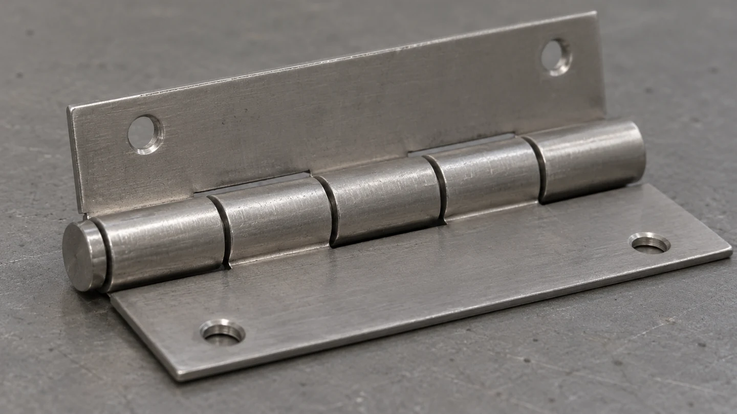
KNUCKLE DETAIL / 말림 이음과 축방향 간격

KNUCKLE DETAIL / 말림 이음과 축방향 간격

04 / BLANK DEVELOPMENT

전개 길이는 최종 말림의 출발값입니다

중립축 가정은 실제 컬링 시편으로 보정합니다.

너클의 전개 길이를 외경 원주로 정하면 판 두께에 따른 안팎의 길이 차이를 놓칩니다. 예비 전개는 중립축 위치를 가정하여 구하지만, 컬링에는 끝단의 진입부와 잔여 직선, 이음 틈 및 금형과의 미끄럼이 함께 작용합니다. 설계 내경과 판 두께로 첫 블랭크를 만든 뒤 단면과 이음 위치를 측정하여 길이를 조정합니다.

탭 사이의 절개는 상대 너클이 들어갈 축방향 공간을 만듭니다. 절개 끝이 너무 날카롭거나 리프와의 연결부가 좁으면 성형 중 변형이 그 위치에 집중될 수 있습니다. 릴리프의 폭과 끝 반경은 핀의 회전 공간뿐 아니라 리프 강성·균열·공구 접근을 함께 검토하여 정하고, 한 항목을 개선하면서 다른 접촉면을 줄이지 않는지 확인합니다.

블랭크 외곽과 장착 구멍을 먼저 완성할지, 성형 뒤에 기준을 잡아 마무리할지는 요구 위치도와 생산 방식에 따라 다릅니다. 성형 중 소재 이동이 큰 경우 평판 때의 구멍 위치가 완성 축선과 어긋날 수 있습니다. 공정별 기준 전달 도면을 만들고, 파일럿·스트리퍼·지지면이 말림 형상을 눌러 위치를 바꾸지 않도록 배치합니다.

중립축 가정은 실제 컬링 시편으로 보정합니다.

전개 길이는 최종 말림의 출발값입니다 — 실무 판단 기준

검토 항목기술적 의미검증·관리 기준
전개 길이중립축·끝단·이음 조건시편 단면으로 보정
탭 간 절개맞물림과 국부 변형폭·끝 반경 검토
구멍 가공 순서완성 축선과 위치 관계성형 전후 위치 비교
기준 전달공정 간 위치 재현파일럿·지지면 확인

전개 길이

기술적 의미
중립축·끝단·이음 조건

검증·관리 기준
시편 단면으로 보정

탭 간 절개

기술적 의미
맞물림과 국부 변형

검증·관리 기준
폭·끝 반경 검토

구멍 가공 순서

기술적 의미
완성 축선과 위치 관계

검증·관리 기준
성형 전후 위치 비교

기준 전달

기술적 의미
공정 간 위치 재현

검증·관리 기준
파일럿·지지면 확인

3D · 교대 너클과 공통 핀의 회전 구조

STRUCTURE & INTERFACE
ID SOLUTECH / 01
인터랙티브 3D를 준비하고 있습니다.
큰 개방 변화

회전하는 리프와 고정된 리프의 너클은 축방향으로 번갈아 배치됩니다. 전체 정렬은 개별 내경과 별도 검증 항목입니다.

드래그·방향키: 회전 / + −: 확대·축소 / Home: 초기화교대 너클과 공통 핀의 회전 구조

내경 합격과 전체 통과는 다릅니다.

Precision.

단계 성형과 동축도

05 / CURLING SEQUENCE

끝단 진입과 말림 닫힘을 단계별로 제어합니다

각 단계가 다음 공구에 제공하는 형상을 확인합니다.

컬링은 평판 탭을 한 번에 원형으로 누르는 과정으로만 이해하기 어렵습니다. 끝단을 먼저 유도하고 탭을 세운 뒤 곡면 안에서 진행시키는 방법처럼, 공구 구성에 맞는 중간 형상이 필요합니다. 단계 수는 소재와 내경·너클 길이·설비 접근에 따라 정하며, 특정 공구의 타수나 성형 각도를 모든 힌지의 표준으로 사용하지 않습니다.

초기 탭의 높이와 끝단 반경이 일정하지 않으면 최종 공구에 닿는 위치가 바뀝니다. 이 차이는 이음이 벌어지거나 끝단이 안으로 접히는 현상으로 나타날 수 있으므로 완성 내경만 측정해서는 원인을 찾기 어렵습니다. 각 중간 단계의 높이·각도·끝단 방향을 남기고, 최종 불량이 시작되는 공정을 역으로 추적합니다.

금형에서 제품을 빼내는 순간에도 형상이 변할 수 있습니다. 공구에 달라붙은 너클을 강제로 이송하면 축선과 리프가 휘므로, 복귀 위치와 스트리핑 지지 면적 및 윤활 공급을 함께 확인합니다. 연속 운전에서는 표면 긁힘과 이송 높이를 관찰하고, 멈춘 시편의 외관이 좋다는 이유만으로 목표 속도를 승인하지 않습니다.

끝단 준비

최종 공구 진입 조건 · 반경·방향 확인

중간 성형

말림 경로의 반복성 · 높이·각도 기록

닫힘 단계

내경과 이음 위치 · 단면·끝단 관찰

끝단 준비

최종 공구 진입 조건 · 반경·방향 확인

끝단 진입과 말림 닫힘을 단계별로 제어합니다 — 실무 판단 기준

검토 항목기술적 의미검증·관리 기준
끝단 준비최종 공구 진입 조건반경·방향 확인
중간 성형말림 경로의 반복성높이·각도 기록
닫힘 단계내경과 이음 위치단면·끝단 관찰
배출·이송복귀 중 형상 보존걸림·긁힘·간섭 확인

끝단 준비

기술적 의미
최종 공구 진입 조건

검증·관리 기준
반경·방향 확인

중간 성형

기술적 의미
말림 경로의 반복성

검증·관리 기준
높이·각도 기록

닫힘 단계

기술적 의미
내경과 이음 위치

검증·관리 기준
단면·끝단 관찰

배출·이송

기술적 의미
복귀 중 형상 보존

검증·관리 기준
걸림·긁힘·간섭 확인

06 / BORE ALIGNMENT

내경 합격과 동축 조립은 별도로 확인합니다

여러 짧은 구멍이 하나의 긴 안내 경로를 만듭니다.

각 너클에 짧은 핀 게이지가 들어가더라도 조립 길이 전체의 핀은 걸릴 수 있습니다. 개별 내경은 국부 크기를 확인하지만 축선의 꺾임과 높이차, 타원 단면을 모두 설명하지 않기 때문입니다. 너클별 단면 치수와 함께 기준 리프에서 본 축의 위치를 검사하고, 필요한 경우 전체 길이를 통과하는 기능 게이지로 경로를 확인합니다.

기능 게이지는 지정한 직경·길이·진입 방향에서 통과 여부를 확인하는 도구입니다. 게이지를 강하게 밀어 넣어 너클을 펴면 검사 자체가 교정 공정이 되어 불량을 숨길 수 있습니다. 허용 삽입력과 부품 지지 방법을 정하고, 통과 실패가 있으면 어느 너클에서 접촉했는지를 표면 흔적이나 단계별 측정으로 찾아냅니다.

복원량은 성형 직후 공구 안에 있는 치수와 제품을 놓았을 때의 치수 차이로 구분합니다. 소재 로트와 두께, 윤활·마찰 및 공구 마모가 변하면 같은 닫힘 위치에서도 결과가 달라질 수 있습니다. 보정은 실제 측정에 근거해 제한된 범위로 적용하고, 지나친 눌림으로 내경만 맞춘 뒤 리프 휨이나 표면 손상을 놓치지 않습니다.

국부 내경

너클별 단면 크기 · 방향·위치별 측정

축선 정렬

전체 핀 경로의 연속성 · 기준면과 위치 연계

기능 게이지

정의된 조립 조건 확인 · 직경·길이·힘 제한

검사 기준

전체 통과 게이지는 정의한 조립 기능을 확인합니다. 개별 너클의 내경·축선·표면 검사를 모두 대신하지 않습니다.

내경 합격과 동축 조립은 별도로 확인합니다 — 실무 판단 기준

검토 항목기술적 의미검증·관리 기준
국부 내경너클별 단면 크기방향·위치별 측정
축선 정렬전체 핀 경로의 연속성기준면과 위치 연계
기능 게이지정의된 조립 조건 확인직경·길이·힘 제한
복원·보정해제 후 형상 변화로트와 조건별 검증

국부 내경

기술적 의미
너클별 단면 크기

검증·관리 기준
방향·위치별 측정

축선 정렬

기술적 의미
전체 핀 경로의 연속성

검증·관리 기준
기준면과 위치 연계

기능 게이지

기술적 의미
정의된 조립 조건 확인

검증·관리 기준
직경·길이·힘 제한

복원·보정

기술적 의미
해제 후 형상 변화

검증·관리 기준
로트와 조건별 검증

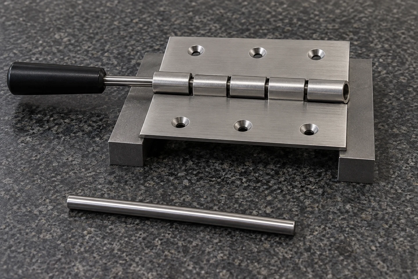
PASSAGE INSPECTION / 지지된 너클의 핀 경로 확인

PASSAGE INSPECTION / 지지된 너클의 핀 경로 확인

Motion.

완성 표면과 간극 계산

07 / FINISHED INTERFACES

표면처리 뒤의 간극을 조립 치수로 사용합니다

내경·핀·끝면에 생기는 변화의 방향이 다릅니다.

너클 내부에 도금이나 도막이 형성되면 유효 내경은 줄고, 핀 외면에 쌓이면 외경은 커집니다. 양쪽이 각각 처리되는 설계에서는 두 변화가 직경 간극을 함께 줄입니다. 공칭 두께만 대입하지 말고 내부 피복의 도달성·국부 편차와 마스킹 조건을 확인하며, 최종 상태에서 조립 가능한 치수를 도면에 명확하게 지정합니다.

도막이 너클 끝면에도 남으면 축방향 틈과 회전 저항이 달라집니다. 침적·건조 중 고임이나 가장자리의 두꺼운 피복은 평균 두께가 합격이어도 접촉을 만들 수 있습니다. 회전 면을 제외할지 조립 순서를 바꿀지 검토하되, 피복을 제거한 영역의 부식 요구와 조립 뒤 처리액 잔류 가능성을 함께 검증합니다.

핀과 너클의 재질 조합은 마찰과 부식, 표면 손상의 양상을 바꿉니다. 윤활제를 넣어 초기 토크가 낮아져도 세척·건조·온도·오염 후에 같은 상태가 유지되는지 확인해야 합니다. 윤활의 종류·양·도포 위치를 승인 조건으로 남기고, 무윤활 사용이 요구되면 실제 표면 조합으로 수명 시험을 수행합니다.

내부 피복

내경 감소 · 국부 두께와 도달성

핀 피복

외경 증가 · 최대 완성 직경

끝면 피복

축방향 틈 감소 · 고임·가장자리 확인

내경·핀·끝면에 생기는 변화의 방향이 다릅니다.

내부 피복

내경 감소 · 국부 두께와 도달성

표면처리 뒤의 간극을 조립 치수로 사용합니다 — 실무 판단 기준

검토 항목기술적 의미검증·관리 기준
내부 피복내경 감소국부 두께와 도달성
핀 피복외경 증가최대 완성 직경
끝면 피복축방향 틈 감소고임·가장자리 확인
마찰면 조건토크와 수명 변화윤활·환경 후 검증

내부 피복

기술적 의미
내경 감소

검증·관리 기준
국부 두께와 도달성

핀 피복

기술적 의미
외경 증가

검증·관리 기준
최대 완성 직경

끝면 피복

기술적 의미
축방향 틈 감소

검증·관리 기준
고임·가장자리 확인

마찰면 조건

기술적 의미
토크와 수명 변화

검증·관리 기준
윤활·환경 후 검증

3D · 지지된 핀 삽입과 클립 안착

PROCESS & VALIDATION
ID SOLUTECH / 02
인터랙티브 3D를 준비하고 있습니다.
핀 완료·클립 준비

핀 머리가 정지 위치에 도달하고 홈 위에 벌린 클립이 놓입니다. 방사 삽입을 위한 접근과 열린 폭을 보여줍니다.

드래그·방향키: 회전 / + −: 확대·축소 / Home: 초기화지지된 핀 삽입과 클립 안착
08 / CLEARANCE CALCULATION

간극 계산은 최악 조합과 적용 가정을 보여줍니다

아래 수치는 설계 원리를 설명하는 가정값입니다.

완성 직경 간극을 C=D−d로 두면 최소값은 Cmin=Dmin−dmax, 최대값은 Cmax=Dmax−dmin입니다. 설명용으로 완성 너클 내경 D=4.10~4.16 mm, 완성 핀 외경 d=3.98~4.00 mm이면 C는 0.10~0.18 mm이고 동심일 때 편측 방사 간극은 0.05~0.09 mm입니다. 이 값은 권장 공차가 아니며 동축도·타원도·거칠기는 별도 항목입니다.

두께가 균일하다는 단순 가정에서는 C후=C전−2tb−2tp로 계산할 수 있습니다. tb는 너클 내부 한 면의 피복 두께, tp는 핀 한 면의 두께이며 단위는 모두 mm입니다. C전=0.10 mm에 tb=0.008 mm, tp=0.005 mm이면 C후=0.074 mm입니다. 실제 국부 두께 범위가 주어지면 최소 간극에는 각 두께의 최대값을 적용합니다.

축방향 총 유격은 E=Lstop−Lstack으로 정리할 수 있습니다. Lstop은 핀 머리와 유지 부품의 실제 정지면 사이 거리, Lstack은 그 사이 너클·와셔의 완성 길이 합입니다. 가정값 30.40±0.05 mm와 30.10±0.10 mm이면 최악 조합 E는 0.15~0.45 mm입니다. 이는 전체 이동량이며 각 너클 사이 틈의 분포나 하중 중 변형을 대신하지 않습니다.

Cmin=Dmin−dmax · Cmax=Dmax−dmin · C후=C전−2tb−2tp · E=Lstop−Lstack

D: 완성 너클 내경, d: 완성 핀 외경, C: 직경 간극, tb·tp: 내부와 핀 한 면의 피복 두께, E: 총 축방향 유격, Lstop: 실제 정지면 간 거리, Lstack: 완성 적층 길이. 모두 mm. 피복식은 균일 두께, 편측 간극은 동심을 가정하며 형상·동축도·하중 변형은 별도 검증합니다.

C=D−d

완성 직경 간극 · 모든 치수 mm

간극 계산은 최악 조합과 적용 가정을 보여줍니다 — 실무 판단 기준

검토 항목기술적 의미검증·관리 기준
C=D−d완성 직경 간극모든 치수 mm
C/2동심 조건의 편측 간극축선 편차는 별도
C후=C전−2tb−2tp균일 피복의 단순 모델국부 편차 실측 필요
E=Lstop−Lstack정지면 사이 총 이동량개별 틈·변형 별도

C=D−d

기술적 의미
완성 직경 간극

검증·관리 기준
모든 치수 mm

C/2

기술적 의미
동심 조건의 편측 간극

검증·관리 기준
축선 편차는 별도

C후=C전−2tb−2tp

기술적 의미
균일 피복의 단순 모델

검증·관리 기준
국부 편차 실측 필요

E=Lstop−Lstack

기술적 의미
정지면 사이 총 이동량

검증·관리 기준
개별 틈·변형 별도

간극은 표면처리 뒤의 값입니다.

Interface.

지지된 조립과 핀 유지

09 / SUPPORTED INSERTION

핀 삽입은 힘과 지지 경로를 함께 관리합니다

리프를 휘게 누르지 않고 축방향 조립을 안내합니다.

핀의 진입 모따기는 첫 구멍을 찾는 데 도움을 주지만 여러 너클의 축선 불일치를 해결하지는 않습니다. 지그는 장착 기준과 너클 위치를 재현하고 삽입 반력이 걸리는 부위를 가까이 지지해야 합니다. 긴 핀을 비스듬히 누르거나 얇은 리프 끝만 받치면 제품이 휘면서 들어가 이후 회전 불량으로 남을 수 있습니다.

삽입 하중–변위 곡선은 첫 진입, 각 너클 통과, 유지부 결합과 최종 정지 위치를 구분하여 해석합니다. 같은 최대 힘이라도 초기에 걸린 경우와 끝에서 유지부가 결합한 경우의 의미가 다릅니다. 정상 샘플과 치수 경계 샘플의 파형을 저장하고, 핀 길이·역삽입·중복 투입 같은 조립 오류도 검출 범위에 포함합니다.

과도한 힘으로 조립을 완료하는 조건은 원인 확인 없이 승인하지 않습니다. 힘 상승 시 핀 직경과 휨, 내경·동축도, 버·피복·윤활을 순서대로 대조하고 금형 교정과 조립 지그 조정을 분리합니다. 제거한 핀의 긁힘 위치와 제품 변형을 남기면 조립 후 토크 불량을 단순한 윤활 부족으로 오판하는 일을 줄일 수 있습니다.

리프를 휘게 누르지 않고 축방향 조립을 안내합니다.

진입 안내

핀과 첫 너클 정렬 · 모따기·방향 확인

핀 삽입은 힘과 지지 경로를 함께 관리합니다 — 실무 판단 기준

검토 항목기술적 의미검증·관리 기준
진입 안내핀과 첫 너클 정렬모따기·방향 확인
반력 지지리프 휨 억제접촉 위치·간격 검토
힘–변위삽입 구간별 이벤트정상·경계 시편 비교
이상 원인치수·표면·지그 구분분해 흔적과 연결

진입 안내

기술적 의미
핀과 첫 너클 정렬

검증·관리 기준
모따기·방향 확인

반력 지지

기술적 의미
리프 휨 억제

검증·관리 기준
접촉 위치·간격 검토

힘–변위

기술적 의미
삽입 구간별 이벤트

검증·관리 기준
정상·경계 시편 비교

이상 원인

기술적 의미
치수·표면·지그 구분

검증·관리 기준
분해 흔적과 연결

10 / PIN RETENTION

핀 유지 구조는 회전면과 별도로 설계합니다

머리·홈·클립이 실제로 멈추는 면을 확인합니다.

솔리드 핀은 머리와 별도 유지 부품, 국부 압입 또는 끝단 성형 등으로 축방향 이동을 제한할 수 있습니다. 어느 리프에 핀을 고정하고 어느 구간이 회전할지 먼저 정하면 유지 영역이 회전면을 손상시키는 설계를 줄일 수 있습니다. 핀 종류를 바꿀 때는 자유 상태 지름만 비교하지 말고 유지 방식과 조립 후 유효 치수를 다시 검토합니다.

클립을 사용하는 경우 홈의 뿌리 지름·폭·측면과 클립 두께, 조립 접근 공간을 함께 지정합니다. 클립이 핀 끝에 걸려 보이는 것만으로 홈에 완전히 안착했다고 판단하지 않습니다. 설치 후의 안착 위치와 축방향 하중 전달면을 확인하며, 도면에 없는 과도한 벌림이나 반복 재사용을 전제로 유지력을 계산하지 않습니다.

스프링 핀은 설치 후 탄성 회복과 구멍 길이의 영향을 받으므로 솔리드 핀과 같은 간극 해석만으로 대체할 수 없습니다. 어떤 방식이든 진동·반복 회전 뒤의 핀 이동과 유지력을 확인해야 하며, 초기 인발력 하나로 수명을 보장하지 않습니다. 유지 시험의 하중 방향과 지그, 전처리 및 합격 기준을 실제 사용 조건에 맞추어 정의합니다.

고정 구간

회전면과 유지면 분리 · 리프별 역할 정의

홈·클립

실제 안착과 하중 전달 · 규격·접근 공간 확인

스프링 핀

설치 후 탄성 회복 · 유효 직경 재평가

고정 구간

회전면과 유지면 분리 · 리프별 역할 정의

핀 유지 구조는 회전면과 별도로 설계합니다 — 실무 판단 기준

검토 항목기술적 의미검증·관리 기준
고정 구간회전면과 유지면 분리리프별 역할 정의
홈·클립실제 안착과 하중 전달규격·접근 공간 확인
스프링 핀설치 후 탄성 회복유효 직경 재평가
유지 시험사용 후 이동 저항진동·회전 후 검사

고정 구간

기술적 의미
회전면과 유지면 분리

검증·관리 기준
리프별 역할 정의

홈·클립

기술적 의미
실제 안착과 하중 전달

검증·관리 기준
규격·접근 공간 확인

스프링 핀

기술적 의미
설치 후 탄성 회복

검증·관리 기준
유효 직경 재평가

유지 시험

기술적 의미
사용 후 이동 저항

검증·관리 기준
진동·회전 후 검사

Validation.

사용 검증과 양산 승인

11 / ROTATION VALIDATION

토크·유격·마모를 같은 수명 시험에 묶습니다

초기 조립감과 사용 후 기능을 따로 기록합니다.

토크 측정은 힌지 축에서 정해진 거리의 힘을 읽거나 직접 토크 센서를 사용하는 방식으로 구성할 수 있습니다. 힘을 사용하는 경우 작용선이 레버에 수직인지 확인하고, 지그 마찰과 커버 무게의 영향을 분리합니다. 시작·정지와 양방향 회전, 각도별 토크를 같은 속도와 환경에서 비교해야 시험 간 차이가 제품 변화인지 판단할 수 있습니다.

반복 시험 중 토크가 낮아지는 것은 길들이기일 수도 있지만 마모와 유지력 저하일 수도 있습니다. 반대로 상승하면 이물·부식·표면 손상 또는 끝면 눌림을 확인합니다. 정해진 주기마다 방사·축방향 유격, 핀 위치와 표면 상태를 함께 측정하고, 기능 한계에 도달한 원인이 핀인지 너클인지 장착부인지 분해하여 확인합니다.

양산 검사는 개발 시험의 핵심 변수를 빠르게 확인하도록 설계합니다. 너클 치수·전체 통과성·조립 하중·완성 토크와 유지부 안착 중 무엇을 전수 또는 샘플 검사할지 위험과 공정 능력에 맞추어 정합니다. 측정 방법의 반복성을 확인하고 불량 발견 시 격리 범위를 소재 로트·금형 상태·조립 설비 이력까지 연결합니다.

토크 방법

힘의 방향과 지그 영향 · 속도·각도·온도 고정

유격 변화

마모와 변형의 지표 · 방사·축방향 구분

핀 위치

유지 상태의 추적 · 주기별 기준 위치

초기 조립감과 사용 후 기능을 따로 기록합니다.

토크 방법

힘의 방향과 지그 영향 · 속도·각도·온도 고정

토크·유격·마모를 같은 수명 시험에 묶습니다 — 실무 판단 기준

검토 항목기술적 의미검증·관리 기준
토크 방법힘의 방향과 지그 영향속도·각도·온도 고정
유격 변화마모와 변형의 지표방사·축방향 구분
핀 위치유지 상태의 추적주기별 기준 위치
양산 검사개발 변수의 빠른 확인반복성·추적성 확보

토크 방법

기술적 의미
힘의 방향과 지그 영향

검증·관리 기준
속도·각도·온도 고정

유격 변화

기술적 의미
마모와 변형의 지표

검증·관리 기준
방사·축방향 구분

핀 위치

기술적 의미
유지 상태의 추적

검증·관리 기준
주기별 기준 위치

양산 검사

기술적 의미
개발 변수의 빠른 확인

검증·관리 기준
반복성·추적성 확보

12 / PRODUCTION RELEASE

컬링부터 장착 상태까지 하나의 승인 조건으로 묶습니다

도면·소재·금형·표면·시험의 연결이 양산 품질을 지탱합니다.

개발 의뢰에는 완성 힌지와 상대 장착부 도면, 재질·조질·두께, 사용 하중과 개방 범위, 표면처리 및 윤활 조건을 준비합니다. 자유 회전인지 위치 유지인지와 허용 유격·토크·핀 이동 기준이 있어야 금형 내경이나 핀 공차를 합리적으로 검토할 수 있습니다. 외관용 모형과 기능 승인 시편은 목적을 구분하여 관리합니다.

승인 기록에는 블랭크 방향과 절단면 조건, 중간 컬링 형상, 완성 내경·축선·간극, 조립 힘–변위와 유지부 검사, 장착 후 수명 시험을 연결합니다. 소재나 도금 업체, 금형 인서트 또는 핀 공급원이 바뀌면 영향을 받는 항목을 골라 재검증합니다. 이전과 이름이 같은 재질이나 부품 번호만으로 기능 동등성을 판단하지 않습니다.

결론적으로 안정적인 프레스 힌지는 말림 형상, 연속된 핀 경로, 완성 상태의 간극과 확실한 유지 구조가 함께 만들어 냅니다. 개별 치수를 검사하는 단계에서 멈추지 않고 장착한 제품의 회전·유격·수명까지 확인하면, 조립되는 힌지와 오래 일정하게 작동하는 힌지 사이의 차이를 개발 과정에서 관리할 수 있습니다.

요구 조건

하중·회전·환경 · 기능 기준 먼저 확정

공정 승인

컬링·표면·조립 연계 · 동일 시편 이력

사용 검증

장착 후 기능 유지 · 토크·유격·핀 이동

요구 조건

하중·회전·환경 · 기능 기준 먼저 확정

컬링부터 장착 상태까지 하나의 승인 조건으로 묶습니다 — 실무 판단 기준

검토 항목기술적 의미검증·관리 기준
요구 조건하중·회전·환경기능 기준 먼저 확정
공정 승인컬링·표면·조립 연계동일 시편 이력
사용 검증장착 후 기능 유지토크·유격·핀 이동
변경 관리동등성 재확인영향 항목 재검증

요구 조건

기술적 의미
하중·회전·환경

검증·관리 기준
기능 기준 먼저 확정

공정 승인

기술적 의미
컬링·표면·조립 연계

검증·관리 기준
동일 시편 이력

사용 검증

기술적 의미
장착 후 기능 유지

검증·관리 기준
토크·유격·핀 이동

변경 관리

기술적 의미
동등성 재확인

검증·관리 기준
영향 항목 재검증

핀 유지와 회전면을 함께 설계합니다.

Start a
Project.

완성·상대물 도면, 소재·조질·두께, 사용 하중과 개방 범위, 토크·유격·유지 기준, 표면처리·윤활 조건을 보내주세요.

Provide finished and mating drawings, stock, temper, gauge, service load, opening range, torque, play and retention limits, finish and lubrication.

개발 상담 · Contact

기술 협의 · Engineering Consultation
도면과 사양을 기준으로 소재·가공·표면처리,
주요 품질 항목과 공급 조건을 함께 검토합니다.


We review drawings and specifications to define materials, manufacturing methods, surface finishes, key quality requirements, and supply conditions.

개발 의뢰하기 · Development Inquiry

    도면 및 기술자료
    Drawings & Technical Documents

    도면 번호와 개정 이력이 표시된 2D·3D 도면을 첨부해 주세요.
    사양서와 검사 기준도 함께 전달할 수 있습니다.
    Attach your 2D or 3D drawings with their drawing numbers and revisions.
    Include specifications and inspection criteria as needed.

    파일을 이곳에 놓아주세요Drag & drop your files here

    선택된 파일 없음 / No files attached

    최대 5개 · 파일당 5MB · 총 15MB / Up to 5 files · 5MB each · 15MB total
    PDF · DWG · DXF · STEP/STP · IGS/IGES · JPG · PNG · ZIP

    * 필수 입력 / Required fields

    STAMPED HINGES

    HINGE ASSEMBLY / 교대로 맞물리는 너클과 공통 핀

    Form the Geometry.
    Validate the Motion.

    Connect blank and curling paths with finished clearance, assembly force and rotational durability.

    CURL · ALIGNMENT · CLEARANCE · RETENTION

    ENGLISH EDITION

    From Curl to Motion.
    Connect Hinge Quality.

    Reviewing stamped hinges through knuckle form, pin assembly and finished clearance

    Aligned axes and retained pins support repeatable movement.

    Hinge quality is established by repeatable motion under the intended load and by a pin that remains in position, beyond the appearance of a round knuckle.

    Connect the cut edge, curling path, alignment of multiple knuckles, clearance after finishing and pin retention within one dimensional scheme. Linking development trials to production inspection helps distinguish binding, play and pin migration rather than treating them as a single assembly problem.

    HINGE FAMILY / 크기와 표면이 다른 프레스 힌지

    HINGE FAMILY / Stamped hinges with different sizes and finishes

    Structure.

    Function and knuckle arrangement

    01 / FUNCTIONAL INTENT

    Free Rotation and Position Holding Need Different Designs

    Define rotational resistance, loading and opening range in application terms.

    A hinge connects two members while allowing relative rotation. Establish the mass, center of gravity and installation orientation of the door or cover, then specify operating effort and opening range. A horizontal lid and vertical door can impose different gravitational moments and axial pin loads on the same small hinge, so envelope dimensions alone do not define suitability.

    A free-running hinge should move without binding under its specified load; a position-holding hinge needs a controlled resistance. Arbitrarily tightening the bores of a free-running design can make torque highly sensitive to surface condition and wear. Separate breakaway torque, running torque and variation with angle to translate intended behavior into inspectable requirements.

    Review forces from opening stops and latches as well. Accidental contact between hinge features is not a defined stop and can concentrate repeated impact in the curl or attachment. Include operating frequency, vibration, contamination, moisture and maintenance access, and reproduce the actual support orientation and mounting condition during validation.

    Rotation function

    Free motion or position holding. Separate breakaway and running torque

    Service load

    Gravity, impact and axial force. Specify direction and application point

    Opening range

    Rotation combined with a stop. Check interference through travel

    Free Rotation and Position Holding Need Different Designs — Review Criteria

    Review itemEngineering significanceVerification or control
    Rotation functionFree motion or position holdingSeparate breakaway and running torque
    Service loadGravity, impact and axial forceSpecify direction and application point
    Opening rangeRotation combined with a stopCheck interference through travel

    Rotation function

    Engineering significance
    Free motion or position holding

    Verification or control
    Separate breakaway and running torque

    Service load

    Engineering significance
    Gravity, impact and axial force

    Verification or control
    Specify direction and application point

    Opening range

    Engineering significance
    Rotation combined with a stop

    Verification or control
    Check interference through travel

    02 / KNUCKLE ARCHITECTURE

    Knuckle Arrangement Defines Support and Assembly Datums

    Distinguish alternating engagement from effective bearing length.

    Knuckles from the two leaves alternate along a common pin. Increasing their number does not automatically distribute load evenly. Differences in bore diameter, axis and end position can cause one knuckle to contact first. Review total length, individual lengths, engagement order and gaps in the assembly drawing rather than relying on the number of segments.

    Axial gaps provide room for assembly and motion, but excessive spacing increases unsupported pin spans. End-face compression can cause heavy rotation even when diametral clearance is sufficient. Include burrs, finish and end-face squareness when checking minimum clearance and maximum play, and evaluate an assembly with accumulated clearance shifted toward one end.

    The relationship between mounting holes and hinge axis locates the cover. Control axis height and parallelism from the leaf datum and relate mounting-hole position to that same reference. A satisfactory loose leaf can become misaligned on a distorted mounting surface or under a different tightening sequence, so retain separate records for the component and its mounted condition.

    Knuckle length

    Actual contact and support span. Inspect lengths and sequence

    Axial gap

    Affects face friction and pin bending. Check both assembly extremes

    Mounting datum

    Relation between leaf and axis. Reproduce mounting condition

    Distinguish alternating engagement from effective bearing length.

    Knuckle length

    Actual contact and support span. Inspect lengths and sequence

    Knuckle Arrangement Defines Support and Assembly Datums — Review Criteria

    Review itemEngineering significanceVerification or control
    Knuckle lengthActual contact and support spanInspect lengths and sequence
    Axial gapAffects face friction and pin bendingCheck both assembly extremes
    Mounting datumRelation between leaf and axisReproduce mounting condition

    Knuckle length

    Engineering significance
    Actual contact and support span

    Verification or control
    Inspect lengths and sequence

    Axial gap

    Engineering significance
    Affects face friction and pin bending

    Verification or control
    Check both assembly extremes

    Mounting datum

    Engineering significance
    Relation between leaf and axis

    Verification or control
    Reproduce mounting condition

    Materials.

    Stock and blank development

    03 / STOCK AND EDGES

    Temper and Cut Edges Establish the Curling Condition

    Specify gauge, direction and surface condition alongside grade.

    Yield and tensile behavior together with thickness influence forming force and elastic recovery. Stainless steel, low-carbon steel and aluminum cannot be substituted at a common tool setting without checking temper and supplied gauge range. In a tight curl, local bendability and the condition of the cut edge may become limiting before the flat sheet tensile strength is informative.

    Record rolling direction in the blank layout. Direction-dependent bending means that rotating a nest solely for material yield can change an established process. If orientation changes, evaluate curl cracking and recovery with representative stock and compare supplier bending data for the relevant grade, thickness and test method rather than importing a universal radius rule.

    Burrs and small edge defects can initiate cracks on the stretched side of a curl. Define burr direction and the required deburring condition without removing enough material to change knuckle width or leaf datums. Connecting pre-form edge observations with post-form crack locations helps distinguish stock behavior from deterioration of cutting edges.

    Grade and temper

    Basis of force and ductility. Link certificates and stock lots

    Gauge range

    Changes curl section and loading. Test measured extremes

    Rolling direction

    Directional forming response. Trace blank orientation

    Grade and temper

    Basis of force and ductility. Link certificates and stock lots

    Temper and Cut Edges Establish the Curling Condition — Review Criteria

    Review itemEngineering significanceVerification or control
    Grade and temperBasis of force and ductilityLink certificates and stock lots
    Gauge rangeChanges curl section and loadingTest measured extremes
    Rolling directionDirectional forming responseTrace blank orientation
    Cut edgeStarting condition for cracks and burrCompare locations before and after forming

    Grade and temper

    Engineering significance
    Basis of force and ductility

    Verification or control
    Link certificates and stock lots

    Gauge range

    Engineering significance
    Changes curl section and loading

    Verification or control
    Test measured extremes

    Rolling direction

    Engineering significance
    Directional forming response

    Verification or control
    Trace blank orientation

    Cut edge

    Engineering significance
    Starting condition for cracks and burr

    Verification or control
    Compare locations before and after forming

    KNUCKLE DETAIL / 말림 이음과 축방향 간격

    KNUCKLE DETAIL / Curl seams and axial gaps

    04 / BLANK DEVELOPMENT

    Developed Length Starts the Curl Geometry

    Calibrate neutral-axis assumptions with actual curled samples.

    Using the outside circumference as the tab length ignores the length difference through sheet thickness. Preliminary development assumes a neutral-axis position, while curling also involves an entry portion, residual straight length, seam opening and sliding against the tool. Start from intended bore and gauge, then adjust the blank from measured cross-sections and seam position.

    Cuts between tabs provide axial space for the opposite leaf. Sharp slot ends or a narrow connection to the leaf can localize deformation during forming. Set relief width and end radius by considering stiffness, cracking and tool access as well as rotational clearance, and check whether a proposed improvement removes support from another functional region.

    Whether to complete the outline and mounting holes before forming or finish selected features afterward depends on positional requirements and production method. Material movement can shift a pre-pierced hole relative to the final hinge axis. Map datum transfer between operations and arrange pilots, strippers and supports so they do not relocate the part by pressing on the curl.

    Calibrate neutral-axis assumptions with actual curled samples.

    Developed Length Starts the Curl Geometry — Review Criteria

    Review itemEngineering significanceVerification or control
    Developed lengthNeutral axis, tip and seamCalibrate with formed sections
    Inter-tab cutsEngagement and local deformationReview width and end radius
    Hole-making sequencePosition relative to final axisCompare before and after forming
    Datum transferLocation repeatability between operationsCheck pilots and supports

    Developed length

    Engineering significance
    Neutral axis, tip and seam

    Verification or control
    Calibrate with formed sections

    Inter-tab cuts

    Engineering significance
    Engagement and local deformation

    Verification or control
    Review width and end radius

    Hole-making sequence

    Engineering significance
    Position relative to final axis

    Verification or control
    Compare before and after forming

    Datum transfer

    Engineering significance
    Location repeatability between operations

    Verification or control
    Check pilots and supports

    3D · Alternating knuckles and common-pin rotation

    STRUCTURE & INTERFACE
    ID SOLUTECH / 01
    Preparing interactive 3D.
    Larger rotation

    Moving and stationary knuckles alternate axially. Overall alignment requires verification separately from local bore size.

    Drag / arrow keys: rotate · + −: zoom · Home: resetAlternating knuckles and common-pin rotation

    Bore size and full passage are separate checks.

    Precision.

    Staged forming and alignment

    05 / CURLING SEQUENCE

    Control Tip Entry and Curl Closure in Stages

    Check the entry geometry passed to each succeeding tool.

    Curling is more than forcing a flat tab into a circle in a single motion. A tool system may first prepare the tip, then raise the tab and guide it around a cavity, with intermediate shapes matched to that system. Choose the number of stages from stock, bore, knuckle length and machine access; one supplier’s stroke count or intermediate angle is not a universal hinge specification.

    Variation in the initial tab height and tip radius changes where it contacts the finishing tool. The result may be an open seam or an inward-folded tip, which final bore measurement alone cannot explain. Retain intermediate height, angle and tip-orientation checks so defects in the finished knuckle can be traced to the operation where they begin.

    The part can also change shape during release from the tool. Forced transfer of a sticking knuckle can distort its axis or the leaf, so verify return position, stripping support and lubricant delivery together. During sustained running, observe scratches and transfer clearance; a satisfactory stationary sample does not by itself validate the target production rate.

    Tip preparation

    Entry condition for finishing tool. Check radius and direction

    Intermediate forming

    Repeatable curl path. Record height and angle

    Closure stage

    Bore and seam position. Inspect section and tip

    Tip preparation

    Entry condition for finishing tool. Check radius and direction

    Control Tip Entry and Curl Closure in Stages — Review Criteria

    Review itemEngineering significanceVerification or control
    Tip preparationEntry condition for finishing toolCheck radius and direction
    Intermediate formingRepeatable curl pathRecord height and angle
    Closure stageBore and seam positionInspect section and tip
    Release and transferPreservation during returnCheck sticking, scratches and interference

    Tip preparation

    Engineering significance
    Entry condition for finishing tool

    Verification or control
    Check radius and direction

    Intermediate forming

    Engineering significance
    Repeatable curl path

    Verification or control
    Record height and angle

    Closure stage

    Engineering significance
    Bore and seam position

    Verification or control
    Inspect section and tip

    Release and transfer

    Engineering significance
    Preservation during return

    Verification or control
    Check sticking, scratches and interference

    06 / BORE ALIGNMENT

    Bore Size and Coaxial Assembly Are Separate Checks

    Several short bores form one long guiding path.

    A short gauge may enter every knuckle while a full-length assembly pin still binds. Local bore size does not capture changes in axis direction, height or ovality. Inspect the individual sections and axis location from the leaf datum, then use a full-length functional gauge when the combined passage is part of the requirement.

    A functional gauge checks passage at a specified diameter, length and approach direction. Forcing it through can straighten the knuckles and turn inspection into an unrecorded sizing operation. Define permissible insertion effort and support, and locate the contacting segment through witness marks or staged measurement when a part fails to pass.

    Separate the geometry while constrained in the tool from the released part. Stock lot, thickness, lubrication, friction and tool wear can change the result at the same closure setting. Apply compensation within a measured operating window, and do not overlook leaf distortion or surface damage caused by excessive sizing merely because the bore becomes acceptable.

    Local bore

    Section size of each knuckle. Measure by position and direction

    Axis alignment

    Continuity of full pin passage. Relate position to leaf datum

    Functional gauge

    Check of a defined fit condition. Define diameter, length and force

    Inspection basis

    A through-gauge verifies its defined assembly function. It does not replace every local bore, axis and surface inspection.

    Bore Size and Coaxial Assembly Are Separate Checks — Review Criteria

    Review itemEngineering significanceVerification or control
    Local boreSection size of each knuckleMeasure by position and direction
    Axis alignmentContinuity of full pin passageRelate position to leaf datum
    Functional gaugeCheck of a defined fit conditionDefine diameter, length and force
    Recovery and compensationShape change after releaseValidate by lot and condition

    Local bore

    Engineering significance
    Section size of each knuckle

    Verification or control
    Measure by position and direction

    Axis alignment

    Engineering significance
    Continuity of full pin passage

    Verification or control
    Relate position to leaf datum

    Functional gauge

    Engineering significance
    Check of a defined fit condition

    Verification or control
    Define diameter, length and force

    Recovery and compensation

    Engineering significance
    Shape change after release

    Verification or control
    Validate by lot and condition

    PASSAGE INSPECTION / 지지된 너클의 핀 경로 확인

    PASSAGE INSPECTION / Checking the pin path through supported knuckles

    Motion.

    Finished surfaces and clearance calculations

    07 / FINISHED INTERFACES

    Use Finished Clearances for Assembly Decisions

    Bore, pin and end faces change in different dimensional directions.

    A deposit inside the knuckle reduces its effective bore, while a deposit on the pin increases its diameter. When both are finished, both changes reduce diametral clearance. Account for coverage, local thickness variation and masking inside the bore rather than using nominal coating thickness alone, and explicitly dimension the condition required after finishing.

    Finish on knuckle end faces also changes axial clearance and rotational resistance. Pools or edge buildup can cause contact despite an acceptable average thickness. Evaluate masking or an alternative assembly sequence while also checking corrosion requirements in uncoated areas and the possibility of process solution remaining inside an assembled hinge.

    The pin and knuckle material pair affects friction, corrosion and surface damage. A lubricant that lowers initial torque must still be evaluated after cleaning, drying, temperature exposure and contamination. Record lubricant type, amount and location in the released process, and validate the actual surface pair when dry operation is required.

    Internal deposit

    Bore reduction. Local thickness and coverage

    Pin deposit

    Diameter increase. Maximum finished diameter

    End-face finish

    Reduced axial space. Check pooling and edges

    Bore, pin and end faces change in different dimensional directions.

    Internal deposit

    Bore reduction. Local thickness and coverage

    Use Finished Clearances for Assembly Decisions — Review Criteria

    Review itemEngineering significanceVerification or control
    Internal depositBore reductionLocal thickness and coverage
    Pin depositDiameter increaseMaximum finished diameter
    End-face finishReduced axial spaceCheck pooling and edges
    Bearing surfaceTorque and durability changesValidate lubrication and exposure

    Internal deposit

    Engineering significance
    Bore reduction

    Verification or control
    Local thickness and coverage

    Pin deposit

    Engineering significance
    Diameter increase

    Verification or control
    Maximum finished diameter

    End-face finish

    Engineering significance
    Reduced axial space

    Verification or control
    Check pooling and edges

    Bearing surface

    Engineering significance
    Torque and durability changes

    Verification or control
    Validate lubrication and exposure

    3D · Supported pin insertion and clip seating

    PROCESS & VALIDATION
    ID SOLUTECH / 02
    Preparing interactive 3D.
    Pin seated; clip ready

    The head reaches its stop and an expanded clip sits above the groove, showing radial approach and opening clearance.

    Drag / arrow keys: rotate · + −: zoom · Home: resetSupported pin insertion and clip seating
    08 / CLEARANCE CALCULATION

    Clearance Calculations Expose Worst-Case Combinations

    The following assumed values illustrate the design method.

    For finished diametral clearance C=D−d, Cmin=Dmin−dmax and Cmax=Dmax−dmin. With illustrative finished bores D=4.10–4.16 mm and pins d=3.98–4.00 mm, clearance is 0.10–0.18 mm; concentric radial clearance is 0.05–0.09 mm. These are not recommended tolerances, and alignment, ovality and roughness remain separate requirements.

    Assuming uniform deposition, Cafter=Cbefore−2tb−2tp, where tb is coating on one bore wall and tp is coating on one pin surface, all in mm. Cbefore=0.10 mm, tb=0.008 mm and tp=0.005 mm give Cafter=0.074 mm. Where local thickness ranges are available, use their upper bounds when checking minimum clearance.

    Total axial end play can be written E=Lstop−Lstack. Lstop is the distance between the actual stopping faces of the pin head and retainer; Lstack sums the finished knuckles and washers between them. Assumed values of 30.40±0.05 mm and 30.10±0.10 mm give worst-case E=0.15–0.45 mm. This is total travel, not the distribution of individual gaps or deformation under load.

    Cmin=Dmin−dmax · Cmax=Dmax−dmin · Cafter=Cbefore−2tb−2tp · E=Lstop−Lstack

    D: finished bore; d: finished pin diameter; C: diametral clearance; tb and tp: deposit on one bore wall and one pin surface; E: total axial play; Lstop: distance between actual stop faces; Lstack: finished stack length. All in mm. Deposition is assumed uniform and radial clearance assumes concentricity; form, alignment and loaded deformation require separate validation.

    C=D−d

    Finished diametral clearance. All dimensions in mm

    Clearance Calculations Expose Worst-Case Combinations — Review Criteria

    Review itemEngineering significanceVerification or control
    C=D−dFinished diametral clearanceAll dimensions in mm
    C/2Radial clearance if concentricAlignment treated separately
    Cafter=Cbefore−2tb−2tpUniform-deposit modelMeasure local variation
    E=Lstop−LstackTotal travel between stopsSeparate local gaps and deflection

    C=D−d

    Engineering significance
    Finished diametral clearance

    Verification or control
    All dimensions in mm

    C/2

    Engineering significance
    Radial clearance if concentric

    Verification or control
    Alignment treated separately

    Cafter=Cbefore−2tb−2tp

    Engineering significance
    Uniform-deposit model

    Verification or control
    Measure local variation

    E=Lstop−Lstack

    Engineering significance
    Total travel between stops

    Verification or control
    Separate local gaps and deflection

    Clearance belongs to the finished condition.

    Interface.

    Supported assembly and pin retention

    09 / SUPPORTED INSERTION

    Control Insertion Force and Its Support Path

    Guide axial assembly without bending the leaves.

    A pin lead-in helps it find the first bore but does not correct misalignment along the knuckle train. The fixture should locate the mounting datums and support the region carrying the insertion reaction. Pressing a long pin at an angle or supporting only the edge of a thin leaf can force assembly by bending the part, leaving a subsequent rotation defect.

    Interpret an insertion force–displacement trace by entry, passage through successive knuckles, retention engagement and final stop. Equal peak force can mean an early obstruction or the intended final engagement. Save traces for acceptable and dimensional-boundary samples, and include wrong pin length, reverse insertion and double loading in the detection assessment.

    Do not accept a high-force assembly condition without establishing its cause. Compare pin diameter and straightness, bore size, alignment, burrs, coating and lubrication, separating forming-tool correction from fixture adjustment. Record scratch locations on removed pins and any part distortion to avoid misidentifying a torque defect as merely insufficient lubrication.

    Guide axial assembly without bending the leaves.

    Entry guidance

    Pin alignment with first knuckle. Check lead-in and orientation

    Control Insertion Force and Its Support Path — Review Criteria

    Review itemEngineering significanceVerification or control
    Entry guidancePin alignment with first knuckleCheck lead-in and orientation
    Reaction supportLimits leaf bendingReview support positions and spacing
    Force–displacementEvents along insertion travelCompare normal and boundary samples
    Fault isolationSeparate size, surface and fixtureConnect with teardown evidence

    Entry guidance

    Engineering significance
    Pin alignment with first knuckle

    Verification or control
    Check lead-in and orientation

    Reaction support

    Engineering significance
    Limits leaf bending

    Verification or control
    Review support positions and spacing

    Force–displacement

    Engineering significance
    Events along insertion travel

    Verification or control
    Compare normal and boundary samples

    Fault isolation

    Engineering significance
    Separate size, surface and fixture

    Verification or control
    Connect with teardown evidence

    10 / PIN RETENTION

    Design Pin Retention Separately from Bearing Surfaces

    Identify the actual stopping faces of the head, groove and clip.

    A solid pin can be restrained by a head and separate retainer, localized interference or end forming. Deciding which member holds the pin and which region rotates helps avoid a retention feature damaging a bearing surface. When changing pin type, reassess retention and installed dimensions instead of comparing only free-state diameters.

    For a clip, specify groove-root diameter, width and sidewalls together with clip thickness and installation access. A clip appearing to catch the pin end does not establish complete seating. Verify its installed position and axial load-transfer faces, and do not assume excessive opening or repeated reuse beyond the hardware specification when evaluating retention.

    Spring pins are affected by installed elastic recovery and engagement length, so a solid-pin clearance model cannot alone justify substitution. For any retention method, check migration and retention after vibration and repeated rotation; initial pullout force does not establish durability. Define test direction, fixture, conditioning and acceptance limits to match service conditions.

    Fixed region

    Separate retention and bearing surfaces. Define each member’s role

    Groove and clip

    Seating and load transfer. Check hardware specification and access

    Spring pin

    Recovery after installation. Reassess installed diameter

    Fixed region

    Separate retention and bearing surfaces. Define each member’s role

    Design Pin Retention Separately from Bearing Surfaces — Review Criteria

    Review itemEngineering significanceVerification or control
    Fixed regionSeparate retention and bearing surfacesDefine each member’s role
    Groove and clipSeating and load transferCheck hardware specification and access
    Spring pinRecovery after installationReassess installed diameter
    Retention testResistance to migration in serviceInspect after vibration and cycling

    Fixed region

    Engineering significance
    Separate retention and bearing surfaces

    Verification or control
    Define each member’s role

    Groove and clip

    Engineering significance
    Seating and load transfer

    Verification or control
    Check hardware specification and access

    Spring pin

    Engineering significance
    Recovery after installation

    Verification or control
    Reassess installed diameter

    Retention test

    Engineering significance
    Resistance to migration in service

    Verification or control
    Inspect after vibration and cycling

    Validation.

    Service validation and production release

    11 / ROTATION VALIDATION

    Track Torque, Play and Wear Through the Same Life Test

    Record initial feel and retained function separately.

    Torque can be measured directly or derived from force at a defined lever arm. For a force-based measurement, check that its line of action is perpendicular to the arm and separate fixture friction and cover weight. Compare breakaway, stopping, both directions and angle-dependent torque at consistent speed and environment to distinguish product change from test variation.

    Falling torque during cycling may represent running-in or progressive wear and loss of retention. Rising torque calls for checks of debris, corrosion, surface damage and end-face loading. At defined intervals, measure radial and axial play, pin position and surface condition, then identify whether a functional limit originated in the pin, knuckles or mounting structure.

    Production checks should rapidly verify the critical variables established in development. Choose full or sampled inspection of knuckle dimensions, overall passage, insertion force, finished torque and retainer seating according to risk and demonstrated process capability. Verify measurement repeatability and connect containment decisions to stock lots, tool condition and assembly-equipment history.

    Torque method

    Force direction and fixture effects. Control speed, angle and temperature

    Play change

    Indicator of wear and deformation. Separate radial and axial motion

    Pin position

    Tracking retention condition. Measure from a fixed reference

    Record initial feel and retained function separately.

    Torque method

    Force direction and fixture effects. Control speed, angle and temperature

    Track Torque, Play and Wear Through the Same Life Test — Review Criteria

    Review itemEngineering significanceVerification or control
    Torque methodForce direction and fixture effectsControl speed, angle and temperature
    Play changeIndicator of wear and deformationSeparate radial and axial motion
    Pin positionTracking retention conditionMeasure from a fixed reference
    Production inspectionRapid checks of validated variablesEnsure repeatability and traceability

    Torque method

    Engineering significance
    Force direction and fixture effects

    Verification or control
    Control speed, angle and temperature

    Play change

    Engineering significance
    Indicator of wear and deformation

    Verification or control
    Separate radial and axial motion

    Pin position

    Engineering significance
    Tracking retention condition

    Verification or control
    Measure from a fixed reference

    Production inspection

    Engineering significance
    Rapid checks of validated variables

    Verification or control
    Ensure repeatability and traceability

    12 / PRODUCTION RELEASE

    Release Curling, Assembly and Mounting as One Condition

    Connect drawing, stock, tooling, finish and test evidence.

    For development, provide the finished hinge and mating mounting drawings, grade, temper, gauge, load, opening range, finish and lubrication. Rotation function and allowable play, torque and pin migration are needed before choosing tool bore or pin tolerances. Manage appearance models and functional approval samples according to their distinct purposes.

    The release record should connect blank orientation and cut-edge condition, intermediate curls, finished bore, axis and clearance, assembly force–displacement, retention checks and mounted life testing. Revalidate affected items after changes in stock, finishing supplier, tool inserts or pin source. A matching material name or part number alone does not demonstrate functional equivalence.

    A consistent stamped hinge combines controlled curl geometry, a continuous pin path, finished clearances and effective retention. Extending verification from individual dimensions to rotation, play and durability in the mounted product allows development to control the difference between a hinge that merely assembles and one that continues to operate consistently.

    Requirements

    Load, motion and environment. Establish functional limits first

    Process release

    Link forming, finishing and assembly. Retain sample-level history

    Service validation

    Retained function after mounting. Torque, play and migration

    Requirements

    Load, motion and environment. Establish functional limits first

    Release Curling, Assembly and Mounting as One Condition — Review Criteria

    Review itemEngineering significanceVerification or control
    RequirementsLoad, motion and environmentEstablish functional limits first
    Process releaseLink forming, finishing and assemblyRetain sample-level history
    Service validationRetained function after mountingTorque, play and migration
    Change controlReconfirm equivalenceRevalidate affected requirements

    Requirements

    Engineering significance
    Load, motion and environment

    Verification or control
    Establish functional limits first

    Process release

    Engineering significance
    Link forming, finishing and assembly

    Verification or control
    Retain sample-level history

    Service validation

    Engineering significance
    Retained function after mounting

    Verification or control
    Torque, play and migration

    Change control

    Engineering significance
    Reconfirm equivalence

    Verification or control
    Revalidate affected requirements

    Design retention alongside bearing surfaces.

    Precision Press Parts

    Precision Press Parts

    Precision Press Parts

    Precision Press Parts

    Precision Press Parts

    ADDITIONAL INFORMATION

    추가 정보

    핵심 요약

    프레스 힌지는 소재·절단면·단계 컬링과 여러 너클의 축선을 맞추고, 완성 표면의 간극과 핀 유지 구조를 검증하는 조립 부품입니다. 사용 하중에서의 회전과 반복 후 유격을 승인 기준에 연결합니다.

    핵심 설계·검증 포인트

    01 / 자유 회전과 위치 유지 요구를 먼저 구분합니다.

    02 / 블랭크 방향과 버·가장자리 상태를 기록합니다.

    03 / 중간 컬링 형상으로 최종 불량의 시작점을 찾습니다.

    04 / 국부 내경과 전체 핀 통과 경로를 따로 확인합니다.

    05 / 도금·도막 뒤의 직경 간극과 축방향 틈을 계산합니다.

    06 / 지지된 조립에서 힘–변위와 유지부 안착을 확인합니다.

    07 / 장착·환경·수명 조건에서 토크와 핀 이동을 검증합니다.

    FAQ · 자주 묻는 기술 질문

    개별 너클의 크기가 맞아도 축선 높이·각도·타원도와 버가 전체 경로를 막을 수 있습니다. 전체 길이 기능 게이지와 위치별 측정으로 접촉 구간을 찾습니다.

    판 두께 안의 중립축, 끝단 진입·잔여 직선·이음 틈을 고려해야 합니다. 예비 계산 뒤 실제 성형 단면으로 전개를 보정합니다.

    축선과 끝면 위치 차이 때문에 일부 너클이 먼저 접촉할 수 있습니다. 실제 접촉 길이와 틈, 장착 상태에서 하중 분포를 검토합니다.

    핀 외면의 성장과 너클 내면의 축소, 끝면 피복을 모두 포함해야 합니다. 균일 피복 가정과 실제 국부 두께 범위를 구분합니다.

    지나치게 낮은 힘은 유지 구간의 부족일 수도 있습니다. 정상 힘–변위, 최종 위치와 유지력을 함께 확인하며 자유 회전 영역과 고정 영역을 구분합니다.

    스프링 핀은 설치 후 탄성 회복과 구멍 길이의 영향을 받습니다. 유지 방식·조립 치수·토크와 수명을 다시 검증해야 합니다.

    홈 뿌리·측면에 규정된 상태로 안착했는지와 축방향 하중 전달면을 확인해야 합니다. 단순한 외관 존재 검사는 완전 안착 검사를 대신하지 않습니다.

    완성·상대물 도면, 재질·조질·두께, 하중·개방 각도, 토크·유격·유지 기준, 표면처리·윤활과 수명 환경을 준비합니다.

    함께 검토할 기술 주제

    성형 기준 전달

    평판 구멍과 완성 축선의 관계를 공정별로 관리합니다.

    피복과 맞춤

    국부 두께가 간극과 끝면 마찰에 미치는 영향을 확인합니다.

    핀 유지와 수명

    초기 안착과 반복 후 핀 이동을 연결해 평가합니다.

    관련 사업분야와 개발 문의

    관련 키워드

    프레스 힌지컬링 성형너클 배열블랭크 전개동축도스프링백완성 간극핀 삽입유지 클립회전 토크수명 검증

    Technical Overview

    A stamped hinge combines stock and edge control, staged curling, aligned knuckles, finished clearances and verified pin retention. Relate acceptance to rotation under service load and play after repeated use.

    Key Design and Validation Points

    01 / Distinguish free-running and position-holding requirements.

    02 / Record blank direction, burr and edge condition.

    03 / Use intermediate curl geometry to locate the origin of defects.

    04 / Check local bore size and the full pin passage separately.

    05 / Calculate diametral and axial clearances after finishing.

    06 / Check force–displacement and retainer seating during supported assembly.

    07 / Validate torque and migration under mounting, environment and life conditions.

    FAQ · Technical Questions and Answers

    Axis height, angular error, ovality or burrs can obstruct the complete passage despite acceptable local size. Use a full-length functional gauge and position-specific measurements to locate contact.

    Account for the neutral axis through thickness, entry tip, residual straight portion and seam. Calibrate preliminary development with actual formed sections.

    Differences in axis and end position can cause early contact at particular segments. Review actual engagement, gaps and mounted loading.

    Include pin growth, bore reduction and end-face deposits. Distinguish a uniform-deposit calculation from actual local thickness ranges.

    Very low force can indicate inadequate retention engagement. Check the approved force–displacement behavior, final position and retention while distinguishing bearing and fixed regions.

    Spring pins depend on installed recovery and engagement length. Revalidate retention method, assembled dimensions, torque and durability.

    Verify engagement with the specified groove root and sidewalls and the axial load-transfer faces. Presence inspection alone does not establish full seating.

    Provide hinge and mating drawings, grade, temper, gauge, load, opening angle, torque, play and retention limits, finishing, lubrication and life-test environment.

    Related Engineering Topics

    Datum transfer in forming

    Control the relationship between flat-sheet holes and the completed hinge axis.

    Finish and fit

    Check how local deposits affect clearance and end-face friction.

    Retention and durability

    Connect initial seating to pin migration after cycling.

    Related Capabilities and Development Inquiry

    Related Keywords

    Stamped hingeCurl formingKnuckle arrangementBlank developmentAxis alignmentSpringbackFinished clearancePin insertionRetaining clipRotation torqueLife validation

    Showing 1-6 of 110 results
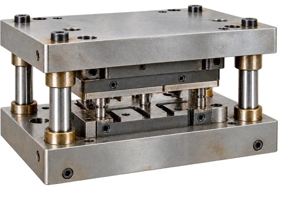
    프레스 금형의 상하형·가이드 포스트·펀치 조립 구조

    프레스 금형 이관: 도면 검토와 보수·개조가 먼저인 이유

    보유한 프레스 금형을 다른 설비로 옮길 때 필요한 도면 대조, 금형 상태 조사, 보수·개조와 시타발을 살펴봅니다. 설비 차이와 남은 생산…
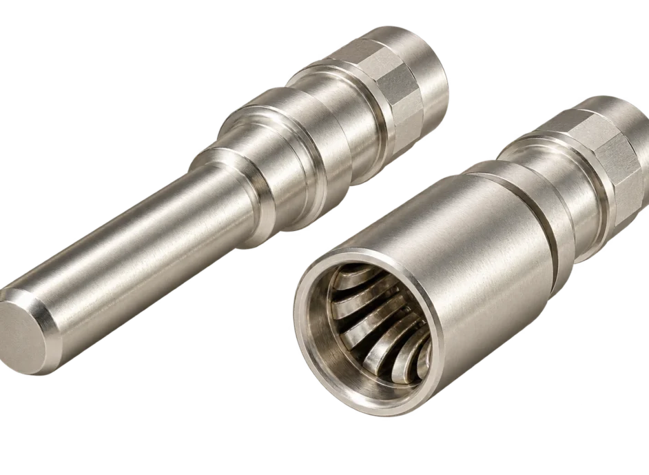
    전기차 급속충전 커넥터의 은색 수핀과 내부 다점 접촉 소켓

    전기차 급속충전 커넥터 접점: 고전류를 받는 핀과 소켓의 구조

    전기차 급속충전 커넥터 접점은 차량 인렛의 핀과 충전 플러그의 소켓이 만드는 고전류 인터페이스입니다. 눈에 잘 보이지 않는 접촉대, 도금과 케이블…
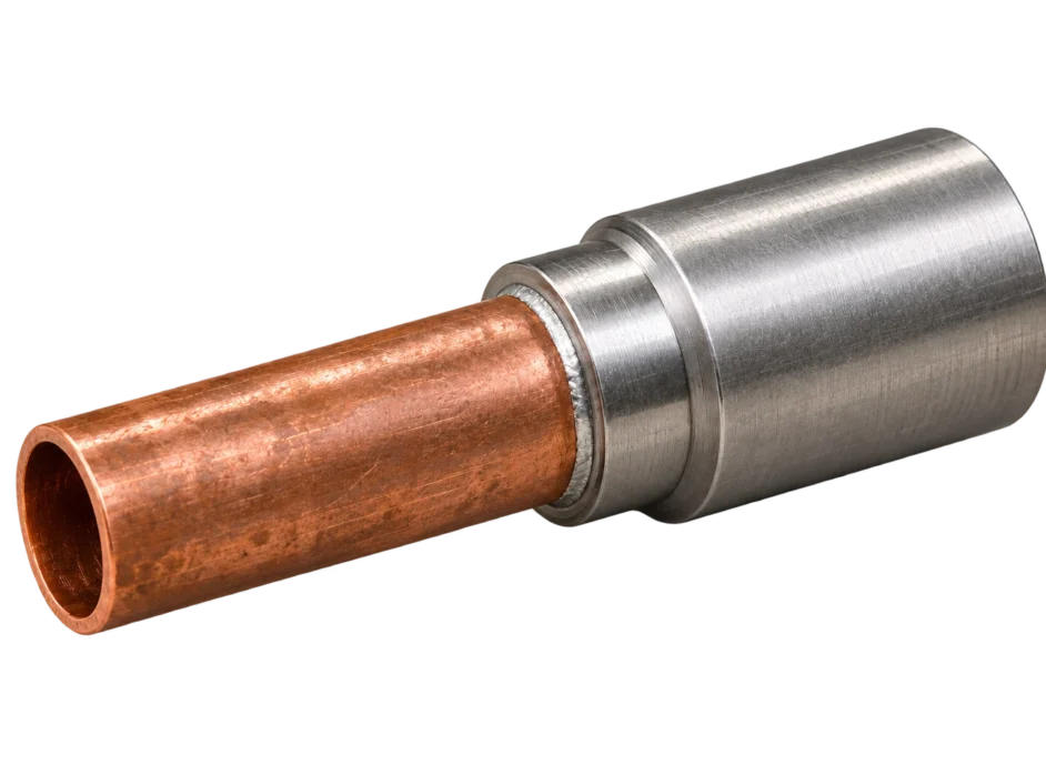
    구리관과 스테인리스 소켓이 은계 브레이징 접합층으로 연결된 조립 구조

    구리–스테인리스 이종 브레이징: 젖음·열간 간극·계면 내구성

    구리–스테인리스 이종 브레이징 설계에서는 젖음, 열간 간극, 용가재와 공정 관리를 함께 검토해야 합니다.
    LOUVER PANEL / 연결된 후드와 열린 통로

    판금 루버 성형: 개구 형상·금형·압력손실을 연결하는 설계

    루버는 판에 구멍을 많이 만드는 작업을 넘어, 절개한 재료를 원하는 방향으로 세워 공기의 통로와 패널의 구조를 함께 만드는 성형입니다.
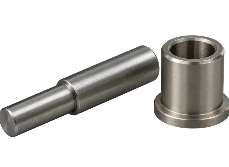
    PLATED INTERFACES / 단계 축과 플랜지 부시

    도금 공차 설계: 기능 치수·두께 분포·완성 검사

    정밀 부품의 표면처리는 재료의 기능을 바꾸면서 조립 공간도 바꿉니다. 외경은 커지고 내경은 작아지며, 마스킹 경계와 국부 성장까지 상대 부품의 움직임에…
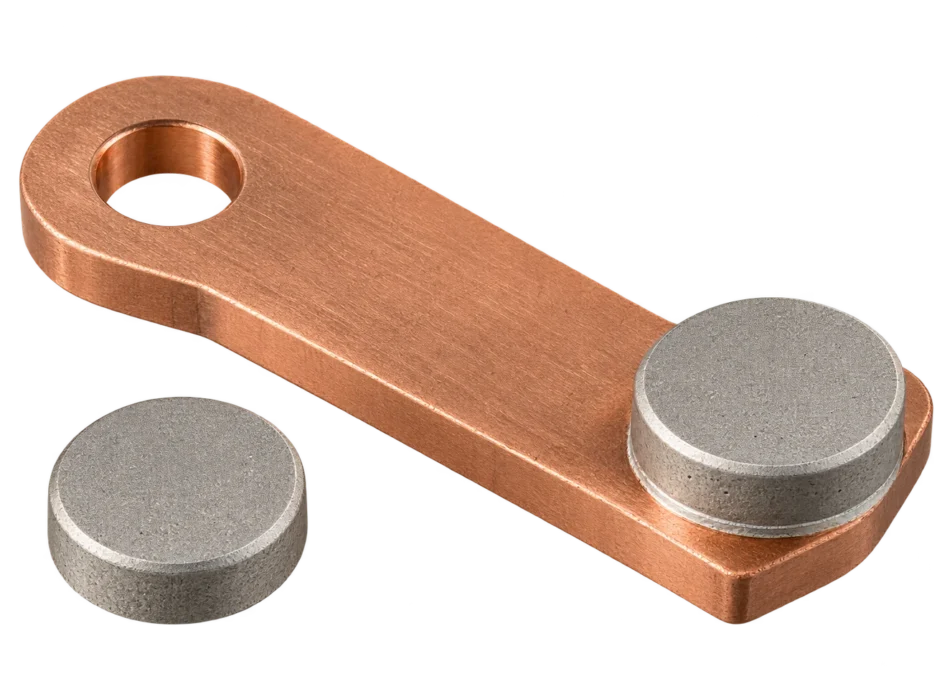
    AgW CONTACT / 구리 지지체에 접합된 복합 접점

    은·텅스텐 접점: 복합 조직·침투 제조·접합 품질의 설계

    두 상의 연결이 접점의 성능을 만듭니다.

    연결 준비 중입니다. 현재 전화 연결을 이용하실 수 있습니다.

    ID SOLUTECH
    LET’S TALK ENGINEERING

    무엇을
    도와드릴까요?

    아이디솔루텍의 제품과 제조 공정,
    기술자료에 대해 질문해 주세요.