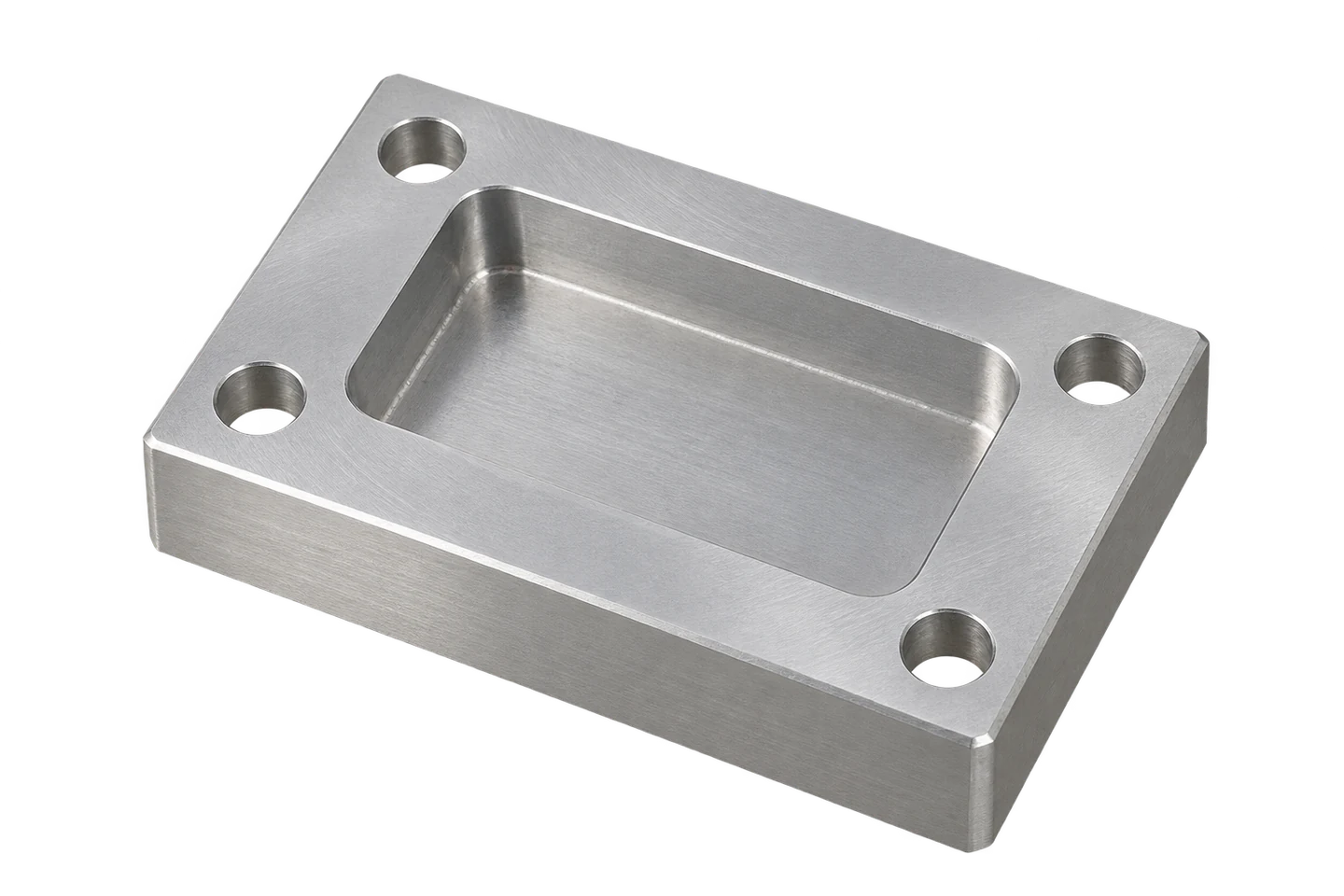
관통 홀과 블라인드 포켓을 가진 절삭 블록

MACHINING PROCESS SELECTION

형상과 수요로 고르는
정밀가공의 경로

CNC·프레스·복합 공정의 기능과 총비용

관통 홀과 블라인드 포켓을 가진 절삭 블록

Shape.
Choose.
Scale.

MACHINING PROCESS SELECTION

관통 홀과 블라인드 포켓을 가진 절삭 블록

형상에서
양산 판단까지

공구 접근과 판재 형상, 기준면·공차·양품 원가를 연결해 생산 경로를 비교합니다.

형상 · 기준면 · 수요 · 양품

Overview.

가공법보다 먼저 기능을 정의합니다

공정을 고르는 순간 형상과 비용, 검사 방식도 함께 결정됩니다. 같은 기능을 어떤 경로로 반복해서 만들 것인지부터 살펴봐야 합니다.

절삭과 판재 성형의 형상 제약을 비교하고, 재료·기준면·수량·설계 변경·후처리를 하나의 판단 흐름으로 연결합니다. 정밀도나 경제성을 공정명만으로 단정하지 않고 실제 양품 생산 조건에서 검토합니다.

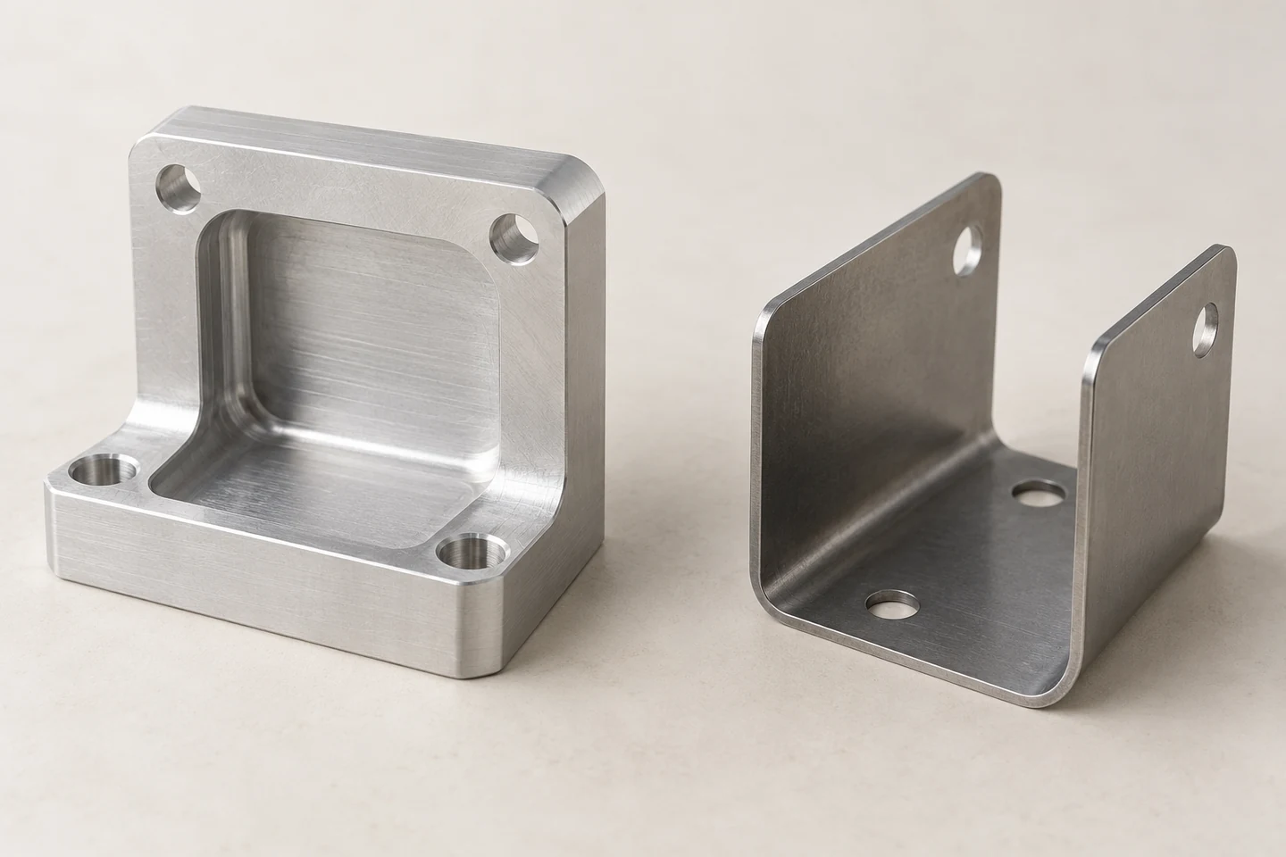
절삭 블록과 일정 두께의 판재 브래킷

절삭 블록과 일정 두께의 판재 브래킷

Structure.

기능과 형상의 조건

01 / FUNCTION FIRST

기능에서 출발하는 공정 지도

형상 이름보다 조립에서 해야 할 일을 먼저 정의합니다.

같은 브래킷이라도 정밀한 축 위치를 유지하는 부품과 넓은 패널을 지지하는 부품은 출발점이 다릅니다. 하중이 들어오는 면, 상대 부품을 정렬하는 면과 외관만 필요한 면을 도면에서 구분하면 어떤 특징을 절삭으로 완성해야 하는지가 드러납니다.

CNC는 축의 운동을 수치로 제어하는 방식이며, 여기서는 선삭·밀링 등 절삭 공정을 뜻합니다. 프레스는 판재를 전단하거나 소성변형하는 공정군입니다. 제어 방식과 성형 원리를 혼동하면 CNC 절곡기 같은 장비를 잘못 분류하게 됩니다.

첫 비교표에는 두 공정의 단가보다 기능 제약을 넣습니다. 막힌 포켓, 두께 변화, 굽힘부, 체결면과 검사 접근을 표시하고, 각 후보가 같은 기능을 구현하는지 확인한 뒤 비용을 비교합니다. 형상이 달라지면 강성과 조립 검증도 다시 필요합니다.

기능면

하중·정렬을 담당 · 도면 기준과 연결

비기능면

외형·취급 요구 · 불필요한 마감 제거

공정 후보

기능을 구현하는 경로 · 형상 변경의 영향 확인

기능에서 출발하는 공정 지도 — 실무 판단 기준

검토 항목기술적 의미검증·관리 기준
기능면하중·정렬을 담당도면 기준과 연결
비기능면외형·취급 요구불필요한 마감 제거
공정 후보기능을 구현하는 경로형상 변경의 영향 확인

기능면

기술적 의미
하중·정렬을 담당

검증·관리 기준
도면 기준과 연결

비기능면

기술적 의미
외형·취급 요구

검증·관리 기준
불필요한 마감 제거

공정 후보

기술적 의미
기능을 구현하는 경로

검증·관리 기준
형상 변경의 영향 확인

02 / GEOMETRY ROUTES

절삭과 판재 성형의 형상 언어

블라인드 포켓과 일정 두께의 굽힘 형상은 다른 제약을 가집니다.

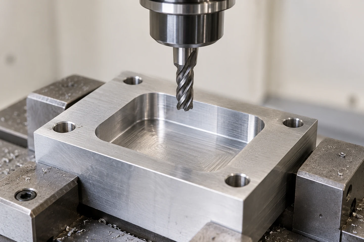
밀링은 공구가 닿는 방향에서 재료를 제거하므로 포켓 깊이·내측 모서리 반경·공구 목 길이가 연결됩니다. 작은 내측 반경을 깊은 위치에 요구하면 긴 소경 공구가 필요해져 생산성이 떨어질 수 있습니다. 닫힌 내부 공간은 별도 공정이나 분할 구조가 필요합니다.

판재 부품은 소재 두께를 바탕으로 전개·절단·굽힘을 연결합니다. 굽힘 반경, 홀과 굽힘선의 거리, 방향별 소재 거동을 검토해야 하며, 완성 외형이 비슷해도 블록 절삭품과 단면 강성은 같지 않습니다. 엠보싱과 리브는 형상과 하중 경로를 함께 바꿉니다.

두 공정의 3D는 한 부품의 단순 대체를 약속하는 비교가 아닙니다. 절삭 포켓에는 실제 바닥이 남고 체결 홀은 관통하며, 판재 경로에는 일정 두께와 굽힘부가 남습니다. 재설계 가능한 면과 유지해야 할 인터페이스를 나누는 데 사용합니다.

포켓

공구 직경·돌출과 연계 · 깊이와 최소 R 동시 검토

판재 굽힘

두께·반경·방향 연계 · 전개와 최종 형상 검증

체결 인터페이스

공정 간 공통 기능 · 위치·접촉 면적 보존

블라인드 포켓과 일정 두께의 굽힘 형상은 다른 제약을 가집니다.

포켓

공구 직경·돌출과 연계 · 깊이와 최소 R 동시 검토

절삭과 판재 성형의 형상 언어 — 실무 판단 기준

검토 항목기술적 의미검증·관리 기준
포켓공구 직경·돌출과 연계깊이와 최소 R 동시 검토
판재 굽힘두께·반경·방향 연계전개와 최종 형상 검증
체결 인터페이스공정 간 공통 기능위치·접촉 면적 보존

포켓

기술적 의미
공구 직경·돌출과 연계

검증·관리 기준
깊이와 최소 R 동시 검토

판재 굽힘

기술적 의미
두께·반경·방향 연계

검증·관리 기준
전개와 최종 형상 검증

체결 인터페이스

기술적 의미
공정 간 공통 기능

검증·관리 기준
위치·접촉 면적 보존

Materials.

소재와 기준의 연결

03 / STOCK CONDITION

재료 상태와 반제품의 선택

동일한 합금명도 반제품과 조질이 달라지면 공정이 달라집니다.

봉재·블록·압출재·판재는 공급 치수와 조직 방향, 잔류응력의 출발 상태가 다릅니다. 설계 재질을 정할 때는 합금명에 조질·열처리·제품 형태를 함께 지정해야 합니다. 절삭성 좋은 상태가 굽힘 성형에도 적합하다고 가정하지 않습니다.

절삭 경로는 가공 여유와 제거 비율을 통해 재료비와 변형 가능성을 검토합니다. 한쪽 면에서 대부분의 재료를 없애는 구조는 가공 중 형상을 만족해도 클램프 해제 후 움직일 수 있습니다. 황삭과 정삭을 나누는 판단은 실제 소재와 형상에 맞춰야 합니다.

판재 경로에서는 두께 편차와 방향성, 표면처리가 전단·굽힘·접촉면에 미치는 영향을 확인합니다. 소재 이용률이 높다는 말만으로 원가를 결정하지 않고 스트립 배치, 스크랩 회수 조건과 소량 구매의 최소 발주량까지 같은 기준으로 계산합니다.

반제품

봉·판·압출의 차이 · 조질·방향·공급 공차

잔류응력

제거 후 재분배 · 해제 후 치수 재측정

판두께

성형과 단면의 출발값 · 입고 로트 편차

반제품

봉·판·압출의 차이 · 조질·방향·공급 공차

재료 상태와 반제품의 선택 — 실무 판단 기준

검토 항목기술적 의미검증·관리 기준
반제품봉·판·압출의 차이조질·방향·공급 공차
잔류응력제거 후 재분배해제 후 치수 재측정
판두께성형과 단면의 출발값입고 로트 편차
재료 이용률구매량 대비 양품량스크랩·최소 발주 반영

반제품

기술적 의미
봉·판·압출의 차이

검증·관리 기준
조질·방향·공급 공차

잔류응력

기술적 의미
제거 후 재분배

검증·관리 기준
해제 후 치수 재측정

판두께

기술적 의미
성형과 단면의 출발값

검증·관리 기준
입고 로트 편차

재료 이용률

기술적 의미
구매량 대비 양품량

검증·관리 기준
스크랩·최소 발주 반영

포켓과 엔드밀의 접근·고정 구성

포켓과 엔드밀의 접근·고정 구성

04 / DATUM TRANSFER

기준면을 잃지 않는 셋업

셋업 수는 단순한 작업 횟수가 아니라 기준을 옮기는 횟수입니다.

절삭에서 한 번 고정해 여러 면을 가공하면 기준 이전을 줄일 수 있지만, 모든 특징이 한 방향에서 접근 가능한 것은 아닙니다. 기준면을 먼저 만들고 후속 공정에서 어떤 면·핀·측정값으로 재현할지 정해야 합니다. 장비 축수가 많아져도 이 논리는 사라지지 않습니다.

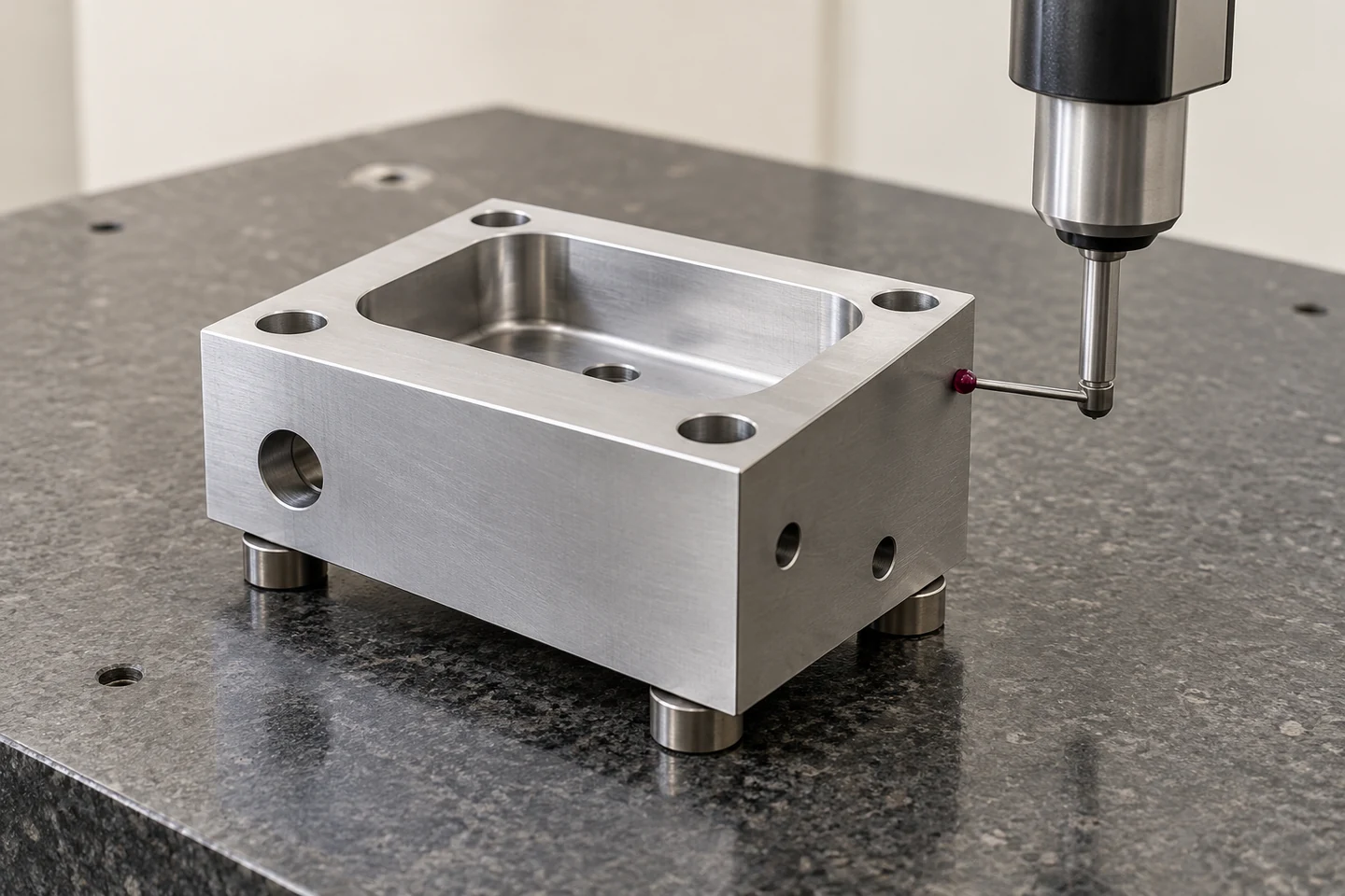
클램프는 절삭력을 받아내면서 기능면을 휘게 만들지 않아야 합니다. 얇은 벽과 넓은 바닥에는 지지 위치가 중요하며, 힘을 크게 주어 흔들림을 없애는 조치는 해제 후 복원 오차를 키울 수 있습니다. 고정 상태와 자유 상태의 측정을 목적에 맞게 구분합니다.

프레스에서는 파일럿·피드·금형 기준이 형상을 단계 사이에 전달합니다. 마지막 성형 이후 재료가 움직일 수 있으므로 홀과 굽힘면의 관계를 어느 상태에서 평가할지 합의합니다. 기능 게이지의 안착 조건도 고객 조립 상태와 일치시켜야 합니다.

셋업 수는 단순한 작업 횟수가 아니라 기준을 옮기는 횟수입니다.

기준면을 잃지 않는 셋업 — 실무 판단 기준

검토 항목기술적 의미검증·관리 기준
기준 이전재고정 오차의 경로1차·2차 기준 명시
지지점힘을 받는 위치클램프 변형 확인
공구 접근홀더·치구 간섭전체 이동 범위 검토
측정 상태자유·구속 상태 차이조립 조건과 정합

기준 이전

기술적 의미
재고정 오차의 경로

검증·관리 기준
1차·2차 기준 명시

지지점

기술적 의미
힘을 받는 위치

검증·관리 기준
클램프 변형 확인

공구 접근

기술적 의미
홀더·치구 간섭

검증·관리 기준
전체 이동 범위 검토

측정 상태

기술적 의미
자유·구속 상태 차이

검증·관리 기준
조립 조건과 정합

3D · 절삭 형상과 판재 경로

STRUCTURE & INTERFACE
ID SOLUTECH / 01
인터랙티브 3D를 준비하고 있습니다.
판재 전개

피어싱 홀을 가진 평판과 굽힘선의 위치를 봅니다. 앞선 절삭 부품과 자동으로 동일한 기능이나 강성을 갖는다는 뜻은 아닙니다.

드래그·방향키: 회전 / + −: 확대·축소 / Home: 초기화절삭 형상과 판재 경로

경제성은 양품 한 개를 완성하는 전체 경로에서 판단합니다.

Precision.

공차와 최종 표면

05 / FEATURE TOLERANCES

공차를 특징별로 배분합니다

장비의 위치 분해능과 완성품 공정능력을 구분합니다.

화면에 표시되는 이동 단위가 부품의 정확도를 보증하지는 않습니다. 열·공구 마모·고정·측정·작업자 변동이 최종 치수에 합쳐집니다. 양산 공차는 실제 소재와 작업 순서에서 얻은 분포, 측정 불확도와 함께 검토합니다.

중요한 것은 모든 치수를 좁히는 것이 아니라 기능을 잃는 조합을 제한하는 일입니다. 체결 홀의 크기와 위치, 지지면의 평면도, 상대면 간 거리의 요구는 서로 다릅니다. 일반공차와 핵심 특성을 분리하면 검사량과 후가공 범위도 분명해집니다.

프레스 부품에서 좁은 공차가 필요하면 리스트라이크·리밍·국부 절삭을 포함하는 경로가 가능할 수 있습니다. 단, 후가공 기준과 성형 후 변형을 포함해 전체 비용을 산정합니다. 공정명만으로 달성 공차를 고정된 숫자로 비교하지 않습니다.

크기

조립 여유·끼워맞춤 · 실측 분포 확인

위치

상대부품 정렬 · 기능 데이텀으로 검사

형상

접촉과 안착 · 평면도·자유 상태

크기

조립 여유·끼워맞춤 · 실측 분포 확인

공차를 특징별로 배분합니다 — 실무 판단 기준

검토 항목기술적 의미검증·관리 기준
크기조립 여유·끼워맞춤실측 분포 확인
위치상대부품 정렬기능 데이텀으로 검사
형상접촉과 안착평면도·자유 상태
측정판정 신뢰성불확도·반복성 검토

크기

기술적 의미
조립 여유·끼워맞춤

검증·관리 기준
실측 분포 확인

위치

기술적 의미
상대부품 정렬

검증·관리 기준
기능 데이텀으로 검사

형상

기술적 의미
접촉과 안착

검증·관리 기준
평면도·자유 상태

측정

기술적 의미
판정 신뢰성

검증·관리 기준
불확도·반복성 검토

06 / FINAL SURFACES

표면·모서리와 후처리

가공 완료와 사용 가능한 표면의 완료는 다를 수 있습니다.

밀링·선삭은 이송 흔적과 방향성을 남기며, 공구 마모나 진동은 이를 바꿉니다. 프레스 전단면에는 진입부와 절단부, 버 방향의 구분이 생깁니다. 접촉·실링·취급 기능이 있는 모서리는 단순한 외관 기준으로 승인하지 않습니다.

버 제거와 모따기는 조립성을 개선하지만 작은 기준 면적이나 홀 입구를 바꿀 수 있습니다. 필요한 모서리 상태를 도면과 한도 샘플에 연결하고, 브러싱·연마로 기능면이 과도하게 둥글어지지 않도록 관리합니다. 표면거칠기와 형상 공차는 별도로 확인합니다.

도금·산화·열처리가 필요한 경우 최종 치수의 검사 시점을 정해야 합니다. 공정 중 합격한 홀이 후처리 후에도 같은 크기일 것이라고 가정하지 않습니다. 마스킹, 세정, 포장과 후처리 업체 간 책임 범위까지 생산 경로에 포함합니다.

절삭 흔적

방향과 공구 상태 · 기능면별 조도 지정

전단 모서리

버·절단면의 방향 · 조립 방향과 한도

모따기

유효 면적 변화 · 과도한 라운딩 방지

절삭 흔적

방향과 공구 상태 · 기능면별 조도 지정

표면·모서리와 후처리 — 실무 판단 기준

검토 항목기술적 의미검증·관리 기준
절삭 흔적방향과 공구 상태기능면별 조도 지정
전단 모서리버·절단면의 방향조립 방향과 한도
모따기유효 면적 변화과도한 라운딩 방지
후처리치수·표면 변화최종 상태 검사

절삭 흔적

기술적 의미
방향과 공구 상태

검증·관리 기준
기능면별 조도 지정

전단 모서리

기술적 의미
버·절단면의 방향

검증·관리 기준
조립 방향과 한도

모따기

기술적 의미
유효 면적 변화

검증·관리 기준
과도한 라운딩 방지

후처리

기술적 의미
치수·표면 변화

검증·관리 기준
최종 상태 검사

기준면과 외측 면을 확인하는 좌표 측정 구성

기준면과 외측 면을 확인하는 좌표 측정 구성

Motion.

생산 흐름과 비용

07 / PRODUCTION FLOW

사이클타임과 생산 흐름

빠른 한 동작보다 완성 양품이 나오는 간격을 봅니다.

절삭시간만 줄여도 공구 교환·로딩·세정·검사가 병목이면 출하량은 그대로일 수 있습니다. 견적에서는 자동 운전시간과 작업자 개입시간을 분리하고 여러 대를 동시에 운영할 수 있는 조건을 명시합니다. 공구 교체 주기도 정지 시간과 함께 기록합니다.

프레스의 스트로크 속도 역시 양품 생산속도와 같지 않습니다. 코일 교환·셋업·금형 보수·스크랩 배출·제품 취출이 실제 운전을 제한합니다. 연속 수요가 아닌 작은 발주가 반복되면 준비시간이 다시 발생할 수 있습니다.

시제품은 기능 확인이 빠른 경로를, 양산은 변동을 관리하기 쉬운 경로를 선택할 수 있습니다. 중간 물량에는 레이저 절단과 절곡, 표준 금형과 국부 절삭 같은 조합도 검토합니다. 단계를 나눌 경우 인계 기준과 재검증 비용을 먼저 정의합니다.

자동시간

장비 점유 · 교환·정지 포함

작업시간

인력의 실제 개입 · 동시 운영 조건

병목

출하량을 제한 · 검사·취출 포함

빠른 한 동작보다 완성 양품이 나오는 간격을 봅니다.

자동시간

장비 점유 · 교환·정지 포함

사이클타임과 생산 흐름 — 실무 판단 기준

검토 항목기술적 의미검증·관리 기준
자동시간장비 점유교환·정지 포함
작업시간인력의 실제 개입동시 운영 조건
병목출하량을 제한검사·취출 포함
발주 패턴준비시간 반복연간량과 로트 분리

자동시간

기술적 의미
장비 점유

검증·관리 기준
교환·정지 포함

작업시간

기술적 의미
인력의 실제 개입

검증·관리 기준
동시 운영 조건

병목

기술적 의미
출하량을 제한

검증·관리 기준
검사·취출 포함

발주 패턴

기술적 의미
준비시간 반복

검증·관리 기준
연간량과 로트 분리

3D · 고정·황삭·정삭·검사

PROCESS & VALIDATION
ID SOLUTECH / 02
인터랙티브 3D를 준비하고 있습니다.
벽면·바닥 정삭

깊어진 포켓과 열린 관통 홀을 확인합니다. 공구의 외측 포락선과 벽면·바닥의 관계를 보여주는 설명 단계입니다.

드래그·방향키: 회전 / + −: 확대·축소 / Home: 초기화고정·황삭·정삭·검사
08 / COST CROSSOVER

양품 수량으로 계산하는 손익분기

금형비와 단가를 같은 범위로 정의해야 계산이 의미를 가집니다.

단순한 비교에서는 경로별 초기비와 양품 한 개당 반복비를 나눕니다. 초기비에는 금형·지그·프로그램·승인을, 반복비에는 소재·가공·검사·후처리와 정상적인 수율 손실을 포함합니다. 양품 기준으로 이미 환산한 비용에 불량률을 다시 더하지 않습니다.

프레스의 초기비가 높고 반복비가 낮은 조건이면 두 총비용이 만나는 수량을 계산할 수 있습니다. 하지만 분모가 양수가 아니거나 실제 수요 범위 안에서 교차하지 않으면 전환을 정당화하는 손익분기점이 없습니다. 이는 공정 선택을 위한 견적 모델이지 시장 단가 표가 아닙니다.

금형 수명·대수 증가·설계 변경·자금 묶임은 직선 비용모델을 깨뜨릴 수 있습니다. 낮음·기준·높음 수요와 수율 시나리오를 비교하고, 발주가 확정되지 않은 누적 예상량을 금형 회수량으로 그대로 사용하지 않습니다. 납기 위험도 별도 판단 항목으로 남깁니다.

Cᵢ(N)=Fᵢ+Nvᵢ ; N*=(Fₚ−F꜀)/(v꜀−vₚ)

Cᵢ: 경로 i의 총비용, Fᵢ: 초기비, vᵢ: 양품 1개당 반복비, N: 양품 수량. p는 프레스, c는 절삭입니다. Fₚ>F꜀이고 v꜀>vₚ일 때 N*가 양의 교차 수량이 됩니다. 동일 기능·동일 범위·일정 수율과 단가를 가정하며, 금형 교체·추가 설비·자금비용·설계 변경은 별도 시나리오입니다. 실제 견적값을 넣기 전에는 어떤 전환 수량도 보증하지 않습니다.

초기비 F

금형·준비·승인 · 동일 범위의 견적

양품 수량으로 계산하는 손익분기 — 실무 판단 기준

검토 항목기술적 의미검증·관리 기준
초기비 F금형·준비·승인동일 범위의 견적
반복비 v양품당 총 반복비수율 중복 반영 금지
수량 N인수 가능한 양품확정 수요 범위
민감도비용 가정의 변화수요·수율·변경 비교

초기비 F

기술적 의미
금형·준비·승인

검증·관리 기준
동일 범위의 견적

반복비 v

기술적 의미
양품당 총 반복비

검증·관리 기준
수율 중복 반영 금지

수량 N

기술적 의미
인수 가능한 양품

검증·관리 기준
확정 수요 범위

민감도

기술적 의미
비용 가정의 변화

검증·관리 기준
수요·수율·변경 비교

작은 공차보다 먼저 필요한 기능을 구분합니다.

Interface.

변경과 복합 경로

09 / DESIGN REVISIONS

설계 변경과 금형 수정

수정할 가능성이 큰 특징은 투자 시점과 연결합니다.

초기 개발에서 홀 위치나 인터페이스가 자주 바뀐다면 프로그램 수정으로 대응 가능한 범위가 가치가 있습니다. 그렇더라도 새 공구·치구·측정 프로그램이 필요할 수 있으므로 절삭의 변경비를 항상 영으로 두지는 않습니다. 변경 전후의 기준과 검사항목을 관리합니다.

프레스 금형 변경은 단순 인서트 교체로 끝날 수도 있고 스트립 레이아웃과 여러 스테이션에 영향을 줄 수도 있습니다. 변경 민감도가 높은 홀·굽힘부·파일럿 위치를 미리 표시하고 교환 가능한 인서트의 범위와 유지보수 책임을 협의합니다.

전환 시점은 시제품 수량이 아니라 기능 요구가 안정되는 시점과 수요 확실성의 조합입니다. 절삭 시제품으로 확인한 결과를 판재 양산품에 그대로 승계하지 않고 재료 상태·강성·피로·표면 차이를 검토합니다. 승인 이력은 설계 버전과 연결합니다.

수정할 가능성이 큰 특징은 투자 시점과 연결합니다.

변경 범위

형상·공차·재질 · 수정 영향표

설계 변경과 금형 수정 — 실무 판단 기준

검토 항목기술적 의미검증·관리 기준
변경 범위형상·공차·재질수정 영향표
절삭 변경공구·치구 추가 가능실제 재준비비
금형 변경스테이션 연쇄 영향인서트·수정성 검토
전환 승인형상과 특성 변화버전별 검증

변경 범위

기술적 의미
형상·공차·재질

검증·관리 기준
수정 영향표

절삭 변경

기술적 의미
공구·치구 추가 가능

검증·관리 기준
실제 재준비비

금형 변경

기술적 의미
스테이션 연쇄 영향

검증·관리 기준
인서트·수정성 검토

전환 승인

기술적 의미
형상과 특성 변화

검증·관리 기준
버전별 검증

10 / COMBINED ROUTES

복합 경로와 외주 경계

전체 형상과 핵심 기능면을 서로 다른 공정으로 완성할 수 있습니다.

성형으로 전체 형상을 만들고 기능 홀을 리밍하거나 지지면을 국부 절삭하는 경로는 유용한 후보입니다. 이때 성형 오차를 후가공 여유로 흡수할 수 있는지, 얇은 부품을 고정하면서 기준을 재현할 수 있는지가 핵심입니다. 공정 하나를 줄이는 것보다 불안정한 공정을 없애는 편이 유리할 수 있습니다.

외주 간 이동에는 세정·방청·운송·재검사와 로트 추적이 생깁니다. 서로 다른 업체가 다른 상태의 도면을 사용하면 후처리 전후 치수 책임이 모호해집니다. 인계 시점의 상태, 허용 흠집과 보관 조건을 작업문서로 연결합니다.

복합 경로의 비교는 첫 단계의 낮은 단가로 끝내지 않습니다. 재고 대기와 품질 피드백 지연, 불량이 발견될 때 이미 진행된 후속 비용을 포함합니다. 시험 생산에서는 주요 특징이 어느 단계에서 형성되고 어느 단계에서 변하는지 측정합니다.

국부 마감

핵심면만 정밀화 · 가공 여유 확보

인계 상태

후처리 전·후 구분 · 도면·검사 책임

대기 재고

흐름의 비용 · 납기·로트 추적

국부 마감

핵심면만 정밀화 · 가공 여유 확보

복합 경로와 외주 경계 — 실무 판단 기준

검토 항목기술적 의미검증·관리 기준
국부 마감핵심면만 정밀화가공 여유 확보
인계 상태후처리 전·후 구분도면·검사 책임
대기 재고흐름의 비용납기·로트 추적
공정 검증특성 변화 위치단계별 측정

국부 마감

기술적 의미
핵심면만 정밀화

검증·관리 기준
가공 여유 확보

인계 상태

기술적 의미
후처리 전·후 구분

검증·관리 기준
도면·검사 책임

대기 재고

기술적 의미
흐름의 비용

검증·관리 기준
납기·로트 추적

공정 검증

기술적 의미
특성 변화 위치

검증·관리 기준
단계별 측정

Validation.

반복성과 승인

11 / PROCESS CAPABILITY

초도 검증과 공정능력

좋은 한 개와 반복 가능한 생산은 다른 증거를 요구합니다.

초도품은 도면 전체의 해석과 공정 순서가 맞는지 확인하는 데 사용합니다. 형상·치수·재질·표면·조립을 확인하되, 측정 상태와 장비도 함께 기록합니다. 첫 제품이 합격했다고 장시간 운전과 소재 로트 간 변동까지 검증된 것은 아닙니다.

반복 생산 검증은 공구 초기·중간·교체 직전, 기계 온도 변화와 재셋업을 포함하도록 계획합니다. 프레스에서는 금형 유지보수 후와 코일 변경이 주요 확인 지점이 될 수 있습니다. 표본 수와 공정능력 지표의 해석은 안정된 공정과 적절한 측정계가 전제입니다.

불량 대응은 치수 하나를 보정하는 데서 멈추지 않습니다. 기준 이동, 공구 마모, 소재 변화와 측정 오류를 구분해 원인과 조치의 연결을 남깁니다. 검증 결과를 견적의 가정과 비교하면 납기·수율·검사 공수의 현실성도 판단할 수 있습니다.

초도품

해석·공정의 확인 · 전체 요구와 조립

반복성

시간·로트 변화 · 공구 수명 구간

측정계

변동의 구분 · 반복성·불확도

좋은 한 개와 반복 가능한 생산은 다른 증거를 요구합니다.

초도품

해석·공정의 확인 · 전체 요구와 조립

초도 검증과 공정능력 — 실무 판단 기준

검토 항목기술적 의미검증·관리 기준
초도품해석·공정의 확인전체 요구와 조립
반복성시간·로트 변화공구 수명 구간
측정계변동의 구분반복성·불확도
조치 이력원인과 결과보정 전후 기록

초도품

기술적 의미
해석·공정의 확인

검증·관리 기준
전체 요구와 조립

반복성

기술적 의미
시간·로트 변화

검증·관리 기준
공구 수명 구간

측정계

기술적 의미
변동의 구분

검증·관리 기준
반복성·불확도

조치 이력

기술적 의미
원인과 결과

검증·관리 기준
보정 전후 기록

12 / RELEASE CONDITIONS

검토용 도면과 발주 조건

견적의 전제와 승인 기준이 일치해야 공정 선택이 완성됩니다.

제작 검토에는 3D 형상과 치수가 있는 도면을 함께 전달하고, 기능 데이텀·핵심 공차·재질 상태·최종 표면을 명시합니다. 연간 수량만 적기보다 초기 발주, 반복 로트, 목표 일정과 설계 변경 가능성을 나누면 현실적인 경로를 제안하기 쉽습니다.

비교 견적의 표에는 포함 공정·검사 성적서·금형 소유권·수정 범위·보관과 유지비를 맞춰 적습니다. 단가가 낮아도 다른 검사나 후처리를 제외했다면 같은 제안을 비교하는 것이 아닙니다. 승인 후 변경은 적용 로트와 재검증 범위를 기록합니다.

결론적으로 공정 선택은 형상·재료·수요·검증을 함께 조율하는 설계 작업입니다. 기능을 만족하는 후보를 먼저 좁히고 양품 기준 총비용과 변경 위험을 비교한 뒤 시험 생산으로 가정을 확인합니다. 이렇게 정한 경로는 수량이나 요구가 달라질 때 다시 검토할 수 있습니다.

기술 입력

형상·기능·재료 · 2D·3D 버전 일치

수요 입력

초기·반복·변경 · 실제 발주 시나리오

견적 범위

금형·검사·후처리 · 포함 항목 통일

기술 입력

형상·기능·재료 · 2D·3D 버전 일치

검토용 도면과 발주 조건 — 실무 판단 기준

검토 항목기술적 의미검증·관리 기준
기술 입력형상·기능·재료2D·3D 버전 일치
수요 입력초기·반복·변경실제 발주 시나리오
견적 범위금형·검사·후처리포함 항목 통일
승인 기록공정·변경·로트재검증 기준

기술 입력

기술적 의미
형상·기능·재료

검증·관리 기준
2D·3D 버전 일치

수요 입력

기술적 의미
초기·반복·변경

검증·관리 기준
실제 발주 시나리오

견적 범위

기술적 의미
금형·검사·후처리

검증·관리 기준
포함 항목 통일

승인 기록

기술적 의미
공정·변경·로트

검증·관리 기준
재검증 기준

초도품의 합격과 반복 생산의 안정성은 서로 다른 증거입니다.

Start a
Project.

도면·재질 상태·기능 공차와 초기·반복 수량을 함께 전달해 주세요.

Share drawings, material condition, functional tolerances, launch demand and repeat lot sizes.

개발 상담 · Contact

기술 협의 · Engineering Consultation
도면과 사양을 기준으로 소재·가공·표면처리,
주요 품질 항목과 공급 조건을 함께 검토합니다.


We review drawings and specifications to define materials, manufacturing methods, surface finishes, key quality requirements, and supply conditions.

개발 의뢰하기 · Development Inquiry

    도면 및 기술자료
    Drawings & Technical Documents

    도면 번호와 개정 이력이 표시된 2D·3D 도면을 첨부해 주세요.
    사양서와 검사 기준도 함께 전달할 수 있습니다.
    Attach your 2D or 3D drawings with their drawing numbers and revisions.
    Include specifications and inspection criteria as needed.

    파일을 이곳에 놓아주세요Drag & drop your files here

    선택된 파일 없음 / No files attached

    최대 5개 · 파일당 5MB · 총 15MB / Up to 5 files · 5MB each · 15MB total
    PDF · DWG · DXF · STEP/STP · IGS/IGES · JPG · PNG · ZIP

    * 필수 입력 / Required fields

    MACHINING PROCESS SELECTION

    관통 홀과 블라인드 포켓을 가진 절삭 블록

    From geometry
    to production choice

    Compare tool access, sheet geometry, datums, tolerances and accepted-part cost as one route.

    Geometry · Datums · Demand · Accepted parts

    ENGLISH EDITION

    Choose the route
    from geometry and demand

    Function and total cost across CNC, pressing and combined routes

    Define the function before selecting the process

    Selecting a process also shapes geometry, cost and inspection. Begin with how the same function will be produced repeatedly.

    Compare the constraints of cutting and sheet forming, then connect stock, datums, demand, revisions and finishing into one decision. Evaluate precision and economics under actual accepted-part production conditions.

    절삭 블록과 일정 두께의 판재 브래킷

    Machined block and constant-thickness sheet bracket

    Structure.

    Function and geometric constraints

    01 / FUNCTION FIRST

    Map processes from the function

    Define the assembly task before choosing a manufacturing label.

    Brackets that locate a precision shaft and brackets that support a broad panel have different starting requirements. Identify loaded faces, alignment features and cosmetic areas on the drawing. This reveals which features need a finishing operation and which can follow the natural capability of the primary process.

    CNC describes numerical control of machine motion; the comparison here concerns CNC cutting processes such as turning and milling. Pressworking is a family of sheet shearing and plastic forming operations. Confusing control architecture with the physical process would misclassify equipment such as a CNC press brake.

    Begin the comparison with functional constraints. Mark blind pockets, thickness changes, bends, bearing faces and inspection access before comparing prices. Each candidate must deliver an equivalent function. A redesigned sheet solution also needs its own stiffness and assembly verification.

    Functional face

    Carries load or locates. Connect to drawing datums

    Other surface

    Envelope and handling. Avoid unnecessary finishing

    Candidate route

    Delivers the function. Verify redesign effects

    Map processes from the function — Review Criteria

    Review itemEngineering significanceVerification or control
    Functional faceCarries load or locatesConnect to drawing datums
    Other surfaceEnvelope and handlingAvoid unnecessary finishing
    Candidate routeDelivers the functionVerify redesign effects

    Functional face

    Engineering significance
    Carries load or locates

    Verification or control
    Connect to drawing datums

    Other surface

    Engineering significance
    Envelope and handling

    Verification or control
    Avoid unnecessary finishing

    Candidate route

    Engineering significance
    Delivers the function

    Verification or control
    Verify redesign effects

    02 / GEOMETRY ROUTES

    The geometry of cutting and sheet forming

    Blind pockets and constant-thickness bends impose different constraints.

    Milling removes material from accessible directions, linking pocket depth, internal corner radius and tool reach. A small corner radius deep inside a pocket may require a slender cutter that restricts productivity. Closed internal spaces may need another process or a split construction.

    Sheet parts connect flat development, cutting and bending around a nominal gauge. Bend radius, hole proximity to a bend and directional material response matter. A similar outside envelope does not give the same section stiffness as a machined block; beads and ribs also change the load path.

    The geometric models compare process constraints rather than promise interchangeable parts. The milled pocket retains a real floor and the mounting bores pass through it; the sheet route retains gauge and bend geometry. Use these views to separate redesign opportunities from interfaces that must remain fixed.

    Pocket

    Coupled to diameter and reach. Review depth and minimum radius

    Sheet bend

    Gauge, radius and direction. Verify blank and formed shape

    Fastening interface

    Shared functional requirement. Preserve location and bearing area

    Blind pockets and constant-thickness bends impose different constraints.

    Pocket

    Coupled to diameter and reach. Review depth and minimum radius

    The geometry of cutting and sheet forming — Review Criteria

    Review itemEngineering significanceVerification or control
    PocketCoupled to diameter and reachReview depth and minimum radius
    Sheet bendGauge, radius and directionVerify blank and formed shape
    Fastening interfaceShared functional requirementPreserve location and bearing area

    Pocket

    Engineering significance
    Coupled to diameter and reach

    Verification or control
    Review depth and minimum radius

    Sheet bend

    Engineering significance
    Gauge, radius and direction

    Verification or control
    Verify blank and formed shape

    Fastening interface

    Engineering significance
    Shared functional requirement

    Verification or control
    Preserve location and bearing area

    Materials.

    Stock and datum systems

    03 / STOCK CONDITION

    Material condition and stock form

    The same alloy name can imply different routes for different stock conditions.

    Bar, plate, extrusion and sheet start with different supply dimensions, directional structure and residual stress. Specify product form and material condition alongside the alloy. A condition selected for easy cutting is not automatically suitable for bending.

    For machining, examine allowance and material removal fraction to understand stock cost and distortion risk. A part with heavy one-sided removal may meet geometry while clamped and move after release. Decisions about separate roughing and finishing stages must follow the actual stock and geometry.

    For sheet routes, review thickness variation, anisotropy and surface treatment at sheared edges, bends and bearing faces. Material utilization alone does not determine cost. Include strip layout, scrap credit and minimum purchasing quantities on a consistent basis.

    Stock form

    Bar, plate or extrusion. Condition, direction and supply tolerance

    Residual stress

    Redistribution after removal. Measure after unclamping

    Sheet gauge

    Starting point for forming and section. Incoming lot variation

    Stock form

    Bar, plate or extrusion. Condition, direction and supply tolerance

    Material condition and stock form — Review Criteria

    Review itemEngineering significanceVerification or control
    Stock formBar, plate or extrusionCondition, direction and supply tolerance
    Residual stressRedistribution after removalMeasure after unclamping
    Sheet gaugeStarting point for forming and sectionIncoming lot variation
    Material utilizationPurchased stock per good partScrap credit and minimum order

    Stock form

    Engineering significance
    Bar, plate or extrusion

    Verification or control
    Condition, direction and supply tolerance

    Residual stress

    Engineering significance
    Redistribution after removal

    Verification or control
    Measure after unclamping

    Sheet gauge

    Engineering significance
    Starting point for forming and section

    Verification or control
    Incoming lot variation

    Material utilization

    Engineering significance
    Purchased stock per good part

    Verification or control
    Scrap credit and minimum order

    포켓과 엔드밀의 접근·고정 구성

    End-mill access and workholding around a pocket

    04 / DATUM TRANSFER

    Preserve datums through setups

    A setup change also transfers the reference system.

    Machining several faces in one clamping can reduce datum transfers, but not every feature is accessible from the same direction. Establish the initial datum and define the surfaces, pins or measurements that reproduce it later. Additional machine axes do not remove this requirement.

    Clamping must resist cutting forces without distorting functional surfaces. Support locations matter for thin walls and broad floors. Increasing clamp force to suppress movement can increase springback after release, so distinguish restrained inspection from free-state inspection according to the function.

    In pressworking, pilots, feed control and tool references transfer location between operations. Material can move after the last forming step. Agree on the state used to evaluate holes relative to bent faces, and make functional gauge seating consistent with the customer assembly.

    A setup change also transfers the reference system.

    Preserve datums through setups — Review Criteria

    Review itemEngineering significanceVerification or control
    Datum transferPath of reclamping errorDefine primary and secondary references
    SupportLocation that reacts forceCheck clamping distortion
    Tool accessHolder and fixture collisionReview the complete motion envelope
    Inspection stateFree versus restrained geometryAlign with assembly conditions

    Datum transfer

    Engineering significance
    Path of reclamping error

    Verification or control
    Define primary and secondary references

    Support

    Engineering significance
    Location that reacts force

    Verification or control
    Check clamping distortion

    Tool access

    Engineering significance
    Holder and fixture collision

    Verification or control
    Review the complete motion envelope

    Inspection state

    Engineering significance
    Free versus restrained geometry

    Verification or control
    Align with assembly conditions

    3D · Machined Features and Sheet Routes

    STRUCTURE & INTERFACE
    ID SOLUTECH / 01
    Preparing interactive 3D.
    Sheet blank

    Inspect the pierced blank and bend locations. It is an alternative geometry, not automatically equivalent in function or stiffness to the machined part.

    Drag / arrow keys: rotate · + −: zoom · Home: resetMachined Features and Sheet Routes

    Evaluate the complete route that delivers an accepted part.

    Precision.

    Tolerance and final surfaces

    05 / FEATURE TOLERANCES

    Allocate tolerances by feature

    Distinguish machine resolution from finished-part capability.

    The motion increment shown on a controller is not a guarantee of part accuracy. Temperature, wear, fixturing, measurement and operator variation combine in the finished dimensions. Review production tolerances against the distribution from the actual material and sequence, together with measurement uncertainty.

    The aim is to constrain combinations that cause functional failure, not tighten every dimension. Hole size and location, bearing-face flatness and face-to-face distance have different roles. Separating general tolerances from critical characteristics makes inspection effort and finishing scope explicit.

    A pressed component may achieve demanding local requirements through restriking, reaming or localized cutting. Include the secondary datum system and post-forming movement in the route and cost. A process name alone cannot define a universal tolerance capability.

    Size

    Clearance and fit. Check measured distribution

    Location

    Mating alignment. Inspect from functional datums

    Form

    Bearing and seating. Flatness and free-state condition

    Size

    Clearance and fit. Check measured distribution

    Allocate tolerances by feature — Review Criteria

    Review itemEngineering significanceVerification or control
    SizeClearance and fitCheck measured distribution
    LocationMating alignmentInspect from functional datums
    FormBearing and seatingFlatness and free-state condition
    MeasurementDecision reliabilityUncertainty and repeatability

    Size

    Engineering significance
    Clearance and fit

    Verification or control
    Check measured distribution

    Location

    Engineering significance
    Mating alignment

    Verification or control
    Inspect from functional datums

    Form

    Engineering significance
    Bearing and seating

    Verification or control
    Flatness and free-state condition

    Measurement

    Engineering significance
    Decision reliability

    Verification or control
    Uncertainty and repeatability

    06 / FINAL SURFACES

    Surface, edges and finishing

    Completing the shape may not complete the functional surface.

    Turning and milling leave directional feed marks that change with wear and vibration. Sheared sheet edges include distinct entry, cut and burr regions. Edges involved in contact, sealing or handling require a functional acceptance criterion rather than a cosmetic judgment alone.

    Deburring and edge breaking improve assembly but can change a small datum land or hole entrance. Link the required condition to drawings and limit samples, and control rounding caused by brushing or polishing. Texture requirements and geometric tolerances need separate checks.

    When coating, oxidation or heat treatment follows forming, define when final dimensions are accepted. A hole approved in process may change during finishing. Include masking, cleaning, packaging and responsibilities between suppliers in the complete route.

    Cutting marks

    Lay and tool condition. Specify texture by function

    Sheared edge

    Burr and edge orientation. Assembly direction and limits

    Edge break

    Changes effective area. Prevent excessive rounding

    Cutting marks

    Lay and tool condition. Specify texture by function

    Surface, edges and finishing — Review Criteria

    Review itemEngineering significanceVerification or control
    Cutting marksLay and tool conditionSpecify texture by function
    Sheared edgeBurr and edge orientationAssembly direction and limits
    Edge breakChanges effective areaPrevent excessive rounding
    FinishingChanges size and surfaceInspect the final condition

    Cutting marks

    Engineering significance
    Lay and tool condition

    Verification or control
    Specify texture by function

    Sheared edge

    Engineering significance
    Burr and edge orientation

    Verification or control
    Assembly direction and limits

    Edge break

    Engineering significance
    Changes effective area

    Verification or control
    Prevent excessive rounding

    Finishing

    Engineering significance
    Changes size and surface

    Verification or control
    Inspect the final condition

    기준면과 외측 면을 확인하는 좌표 측정 구성

    Coordinate measurement of datum and external faces

    Motion.

    Production flow and cost

    07 / PRODUCTION FLOW

    Cycle time and production flow

    Evaluate the output interval of accepted parts.

    Reducing cutting time may not increase shipments if tool changes, loading, cleaning or inspection remain the bottleneck. Separate automatic machine time from operator attendance in the quotation, and state the conditions for tending multiple machines. Include tool replacement downtime.

    Press stroke rate is likewise different from accepted-part output. Coil changes, setup, die maintenance, scrap handling and extraction limit actual running. Repeated small orders can incur fresh preparation time even when the cumulative quantity looks large.

    A prototype route can prioritize rapid functional learning while production prioritizes controlled variation. Intermediate demand may suit laser cutting and bending or standard tooling with localized machining. Define transfer criteria and requalification costs before switching routes.

    Automatic time

    Machine occupancy. Include changes and stops

    Labor time

    Actual attendance. State multi-machine assumptions

    Bottleneck

    Constrains shipments. Include inspection and extraction

    Evaluate the output interval of accepted parts.

    Automatic time

    Machine occupancy. Include changes and stops

    Cycle time and production flow — Review Criteria

    Review itemEngineering significanceVerification or control
    Automatic timeMachine occupancyInclude changes and stops
    Labor timeActual attendanceState multi-machine assumptions
    BottleneckConstrains shipmentsInclude inspection and extraction
    Order patternRepeated preparationSeparate annual volume and lot size

    Automatic time

    Engineering significance
    Machine occupancy

    Verification or control
    Include changes and stops

    Labor time

    Engineering significance
    Actual attendance

    Verification or control
    State multi-machine assumptions

    Bottleneck

    Engineering significance
    Constrains shipments

    Verification or control
    Include inspection and extraction

    Order pattern

    Engineering significance
    Repeated preparation

    Verification or control
    Separate annual volume and lot size

    3D · Workholding, Roughing, Finishing and Inspection

    PROCESS & VALIDATION
    ID SOLUTECH / 02
    Preparing interactive 3D.
    Finish wall and floor

    The deeper pocket and open bores expose the relationship of the cutter envelope to the finished wall and floor.

    Drag / arrow keys: rotate · + −: zoom · Home: resetWorkholding, Roughing, Finishing and Inspection
    08 / COST CROSSOVER

    Break-even based on accepted quantity

    Tooling and recurring costs must cover the same scope.

    A simple comparison separates initial investment from recurring cost per accepted part. Initial cost includes tooling, fixtures, programming and qualification; recurring cost includes material, processing, inspection, finishing and normal yield loss. Do not apply a scrap allowance twice when cost is already expressed per good part.

    If pressing has higher initial cost and lower recurring cost, the intersection of the two total-cost lines gives a break-even quantity. A nonpositive denominator or an intersection outside plausible demand does not support switching. This is a quotation model, not a table of market prices.

    Tool replacement, additional equipment, design changes and tied-up capital can invalidate linear cost assumptions. Compare low, base and high scenarios for demand and yield. Uncommitted cumulative forecasts should not automatically become tooling recovery quantities, and delivery risk remains a separate decision.

    Cᵢ(N)=Fᵢ+Nvᵢ ; N*=(Fₚ−F꜀)/(v꜀−vₚ)

    Cᵢ is total cost for route i; Fᵢ is initial cost; vᵢ is recurring cost per accepted part; N is accepted quantity. p denotes pressing and c denotes machining. For the common case Fₚ>F꜀ and v꜀>vₚ, N* is a positive intersection. Equivalent function and scope, constant yield and constant recurring cost are assumed. Tool replacement, extra capacity, financing and revisions require separate scenarios. No switch quantity is guaranteed without actual quotations.

    Initial cost F

    Tooling, setup and qualification. Compare equal scope

    Break-even based on accepted quantity — Review Criteria

    Review itemEngineering significanceVerification or control
    Initial cost FTooling, setup and qualificationCompare equal scope
    Recurring cost vTotal per accepted partAvoid double-counting yield
    Quantity NAccepted deliverable partsUse credible demand
    SensitivityChanging assumptionsCompare demand, yield and revisions

    Initial cost F

    Engineering significance
    Tooling, setup and qualification

    Verification or control
    Compare equal scope

    Recurring cost v

    Engineering significance
    Total per accepted part

    Verification or control
    Avoid double-counting yield

    Quantity N

    Engineering significance
    Accepted deliverable parts

    Verification or control
    Use credible demand

    Sensitivity

    Engineering significance
    Changing assumptions

    Verification or control
    Compare demand, yield and revisions

    Define the required function before tightening tolerances.

    Interface.

    Revisions and combined routes

    09 / DESIGN REVISIONS

    Design changes and tooling revisions

    Connect unstable features to the timing of investment.

    When hole locations or interfaces are changing during development, programmable flexibility has value. Machining changes can still require new tools, fixtures or inspection programs, so their cost should not automatically be set to zero. Track datums and acceptance characteristics across revisions.

    A die revision may involve a replaceable insert or affect the strip layout and several stations. Identify sensitive holes, bends and pilot positions early. Agree on the extent of replaceable tooling and who maintains it.

    A transition depends on requirements becoming stable and demand becoming credible, not merely on a prototype quantity. Results from machined prototypes cannot automatically qualify formed production parts. Review differences in material condition, stiffness, fatigue and surfaces, with approval linked to design revision.

    Connect unstable features to the timing of investment.

    Revision scope

    Geometry, tolerance and material. Map affected operations

    Design changes and tooling revisions — Review Criteria

    Review itemEngineering significanceVerification or control
    Revision scopeGeometry, tolerance and materialMap affected operations
    Machining revisionPossible tools and fixturesActual re-preparation cost
    Die revisionEffects across stationsReview insert replaceability
    Transition approvalGeometry and property changesQualification by revision

    Revision scope

    Engineering significance
    Geometry, tolerance and material

    Verification or control
    Map affected operations

    Machining revision

    Engineering significance
    Possible tools and fixtures

    Verification or control
    Actual re-preparation cost

    Die revision

    Engineering significance
    Effects across stations

    Verification or control
    Review insert replaceability

    Transition approval

    Engineering significance
    Geometry and property changes

    Verification or control
    Qualification by revision

    10 / COMBINED ROUTES

    Combined routes and supplier interfaces

    Different operations can create the envelope and the critical interfaces.

    Forming the envelope and then reaming critical holes or machining a local bearing face can be a useful route. The key questions are whether finishing allowance absorbs forming variation and whether a thin part can reproduce its datums under clamping. Eliminating an unstable operation can matter more than removing one operation.

    Supplier transfers add cleaning, corrosion protection, transport, reinspection and lot traceability. Different drawing states can obscure responsibility for pre- and post-treatment dimensions. Define the transfer condition, acceptable handling marks and storage requirements.

    Compare combined routes beyond the first low-priced operation. Include waiting inventory, delayed quality feedback and downstream cost already added before a defect is found. During trials, measure when each critical feature is created and when it changes.

    Local finishing

    Precision only where needed. Provide adequate allowance

    Transfer state

    Before or after treatment. Drawing and inspection ownership

    Waiting inventory

    Cost of process flow. Lead time and lot traceability

    Local finishing

    Precision only where needed. Provide adequate allowance

    Combined routes and supplier interfaces — Review Criteria

    Review itemEngineering significanceVerification or control
    Local finishingPrecision only where neededProvide adequate allowance
    Transfer stateBefore or after treatmentDrawing and inspection ownership
    Waiting inventoryCost of process flowLead time and lot traceability
    Route validationWhere characteristics changeMeasure at each relevant stage

    Local finishing

    Engineering significance
    Precision only where needed

    Verification or control
    Provide adequate allowance

    Transfer state

    Engineering significance
    Before or after treatment

    Verification or control
    Drawing and inspection ownership

    Waiting inventory

    Engineering significance
    Cost of process flow

    Verification or control
    Lead time and lot traceability

    Route validation

    Engineering significance
    Where characteristics change

    Verification or control
    Measure at each relevant stage

    Validation.

    Repeatability and approval

    11 / PROCESS CAPABILITY

    First-article verification and capability

    One good part and a repeatable process need different evidence.

    First-article inspection checks whether the drawing interpretation and route are correct. Verify geometry, dimensions, material, surfaces and assembly while recording measurement conditions and equipment. Passing the first part does not qualify long runs or variation between stock lots.

    Plan repeatability checks across early, middle and late tool life, machine warm-up and setup changes. For pressing, die maintenance and coil changes can be relevant checkpoints. Capability indices and sampling plans require an appropriate measurement system and a sufficiently stable process.

    Corrective action should extend beyond changing one offset. Distinguish datum shift, wear, stock changes and measurement error, then document the causal link to the remedy. Comparing trial results with quotation assumptions also tests the realism of lead time, yield and inspection effort.

    First article

    Interpretation and route. Full requirements and assembly

    Repeatability

    Time and lot changes. Across tool life

    Measurement system

    Separate variation sources. Repeatability and uncertainty

    One good part and a repeatable process need different evidence.

    First article

    Interpretation and route. Full requirements and assembly

    First-article verification and capability — Review Criteria

    Review itemEngineering significanceVerification or control
    First articleInterpretation and routeFull requirements and assembly
    RepeatabilityTime and lot changesAcross tool life
    Measurement systemSeparate variation sourcesRepeatability and uncertainty
    Action historyCause and effectRecord before and after

    First article

    Engineering significance
    Interpretation and route

    Verification or control
    Full requirements and assembly

    Repeatability

    Engineering significance
    Time and lot changes

    Verification or control
    Across tool life

    Measurement system

    Engineering significance
    Separate variation sources

    Verification or control
    Repeatability and uncertainty

    Action history

    Engineering significance
    Cause and effect

    Verification or control
    Record before and after

    12 / RELEASE CONDITIONS

    Drawings and purchasing conditions

    Process selection is complete when quotation assumptions match acceptance.

    Provide a dimensioned drawing together with the 3D model, identifying functional datums, critical tolerances, material condition and final surfaces. Separate launch demand, repeat lot size, target schedule and likely revisions instead of supplying annual quantity alone. This enables a realistic route proposal.

    Normalize quotation scope for operations, inspection reports, tooling ownership, modification allowances, storage and maintenance. A lower unit price that excludes inspection or finishing is a different offer. After approval, record the affected lots and requalification scope of every change.

    Process selection is a design task that coordinates geometry, material, demand and verification. Narrow the candidates by function, compare accepted-part total cost and revision risk, then test the assumptions in production trials. Revisit the chosen route when quantity or requirements change.

    Technical input

    Geometry, function and material. Matching 2D and 3D revisions

    Demand input

    Launch, repeat and revisions. Credible order scenarios

    Quotation scope

    Tooling, inspection and finishing. Normalize included items

    Technical input

    Geometry, function and material. Matching 2D and 3D revisions

    Drawings and purchasing conditions — Review Criteria

    Review itemEngineering significanceVerification or control
    Technical inputGeometry, function and materialMatching 2D and 3D revisions
    Demand inputLaunch, repeat and revisionsCredible order scenarios
    Quotation scopeTooling, inspection and finishingNormalize included items
    Approval recordRoute, revision and lotRequalification criteria

    Technical input

    Engineering significance
    Geometry, function and material

    Verification or control
    Matching 2D and 3D revisions

    Demand input

    Engineering significance
    Launch, repeat and revisions

    Verification or control
    Credible order scenarios

    Quotation scope

    Engineering significance
    Tooling, inspection and finishing

    Verification or control
    Normalize included items

    Approval record

    Engineering significance
    Route, revision and lot

    Verification or control
    Requalification criteria

    One approved part and stable production are different evidence.

    CNC Precision Machining

    CNC Precision Machining

    CNC Precision Machining

    CNC Precision Machining

    CNC Precision Machining

    ADDITIONAL INFORMATION

    추가 정보

    핵심 요약

    기능을 만족하는 형상을 먼저 확인하고, 같은 검사·후처리 범위의 양품 기준 총비용을 비교합니다. 공정 선택은 초도품과 반복 생산 검증을 거쳐 확정하며 수요와 설계가 바뀌면 다시 평가합니다.

    핵심 설계·검증 포인트

    01 / 포켓·두께 변화·굽힘·공구 접근을 형상별로 검토합니다.

    02 / 합금명과 함께 조질·반제품·표면 상태를 지정합니다.

    03 / 셋업마다 기준면이 어떻게 전달되는지 기록합니다.

    04 / 핵심 기능 공차와 일반공차를 나누어 관리합니다.

    05 / 준비·수율·후처리·검사를 포함한 양품 원가를 비교합니다.

    06 / 수요 확실성과 설계 변경에 대한 민감도를 확인합니다.

    07 / 초도 승인과 양산 반복성의 증거를 구분합니다.

    FAQ · 자주 묻는 기술 질문

    고정된 수량은 없습니다. 금형·준비비와 양품당 반복비가 같은 범위로 비교되어야 하며 수요·변경·금형 수명을 함께 검토합니다.

    완성품은 장비·공구·고정·열·측정의 영향을 받습니다. 실제 특징별 공정능력으로 판단해야 합니다.

    기능의 초기 확인에는 도움이 되지만 재료 상태·강성·굽힘부·표면이 달라질 수 있어 양산 경로 검증이 필요합니다.

    기능상 필요한 면을 구분해야 합니다. 일괄적인 낮은 조도는 가공·검사 비용을 높일 수 있습니다.

    접근성을 높일 수 있지만 기준 설정과 고정 변형, 충돌·측정 검토는 여전히 필요합니다.

    가능한 후보입니다. 성형 후 기준 재현과 고정, 여유 및 총비용을 확인합니다.

    실제 발주 로트, 확정 수요, 변경 가능성과 회수 기간을 나눠 검토해야 합니다.

    2D·3D, 재질 상태, 기능 데이텀, 핵심 공차, 후처리와 검사 범위, 초기·반복 수량 및 일정이 필요합니다.

    함께 검토할 기술 주제

    기능 데이텀과 공차

    조립 위치와 접촉면의 요구를 공정·측정 기준에 연결합니다.

    절삭 표면과 후처리

    공구 흔적·버·도금 이후 최종 표면의 요구를 정리합니다.

    판재 성형과 강성

    두께·굽힘·리브가 하중 경로와 변형에 미치는 영향을 비교합니다.

    관련 사업분야와 개발 문의

    관련 키워드

    CNC 가공프레스 가공공정 선택기능 데이텀공구 접근양품 원가손익분기금형 투자공정능력복합 가공초도 승인

    Technical Overview

    First confirm geometry that meets the function, then compare total cost per accepted part over the same inspection and finishing scope. Qualify the route through first articles and repeat production, and reassess it when demand or design changes.

    Key Design and Validation Points

    01 / Review pockets, thickness changes, bends and tool access.

    02 / Specify condition, stock form and surface alongside the alloy.

    03 / Record how datums transfer through each setup.

    04 / Separate critical functional tolerances from general tolerances.

    05 / Include preparation, yield, finishing and inspection in cost.

    06 / Check sensitivity to demand confidence and design revisions.

    07 / Distinguish first-article approval from production repeatability.

    FAQ · Technical Questions and Answers

    There is no universal threshold. Compare initial and recurring accepted-part costs over equal scope, including demand, revisions and tooling life.

    Finished parts depend on the machine, tools, fixturing, temperature and measurement. Judge actual capability for each feature.

    It can establish early function, but material condition, stiffness, bends and surfaces may change. The production route needs verification.

    Distinguish functional surfaces. A blanket fine finish can add machining and inspection cost without benefit.

    It can improve access, while datum definition, distortion, collision and measurement still need review.

    Yes as a candidate route, provided datums, clamping, allowance and total cost are verified.

    Review real order sizes, committed demand, revision likelihood and investment recovery separately.

    Matching 2D and 3D data, material condition, datums, critical tolerances, finishing, inspection, launch and repeat quantities, and schedule.

    Related Engineering Topics

    Functional datums and tolerance

    Connect mating alignment and bearing-face requirements to processing and inspection.

    Machined surfaces and finishing

    Define tool marks, burrs and the final surface after treatment.

    Sheet forming and stiffness

    Compare how gauge, bends and ribs affect load paths and deformation.

    Related Capabilities and Development Inquiry

    Related Keywords

    CNC machiningPressworkingProcess selectionFunctional datumTool accessAccepted-part costBreak-evenTooling investmentProcess capabilityCombined routesFirst-article approval

    Showing 1-6 of 110 results
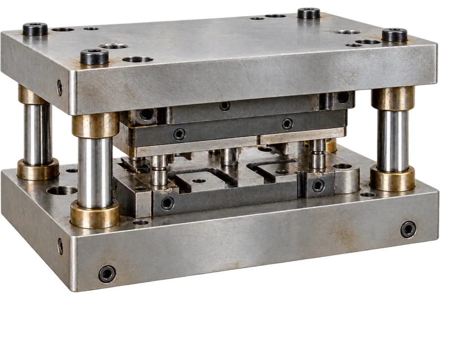
    프레스 금형의 상하형·가이드 포스트·펀치 조립 구조

    프레스 금형 이관: 도면 검토와 보수·개조가 먼저인 이유

    보유한 프레스 금형을 다른 설비로 옮길 때 필요한 도면 대조, 금형 상태 조사, 보수·개조와 시타발을 살펴봅니다. 설비 차이와 남은 생산…
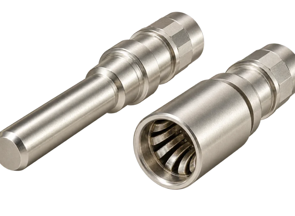
    전기차 급속충전 커넥터의 은색 수핀과 내부 다점 접촉 소켓

    전기차 급속충전 커넥터 접점: 고전류를 받는 핀과 소켓의 구조

    전기차 급속충전 커넥터 접점은 차량 인렛의 핀과 충전 플러그의 소켓이 만드는 고전류 인터페이스입니다. 눈에 잘 보이지 않는 접촉대, 도금과 케이블…
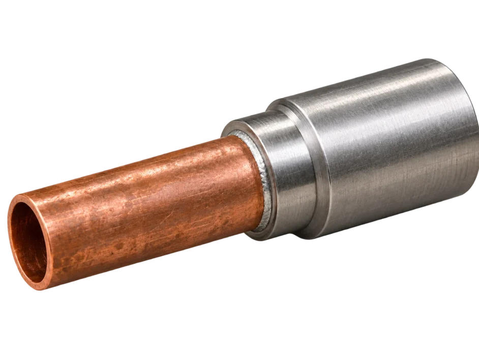
    구리관과 스테인리스 소켓이 은계 브레이징 접합층으로 연결된 조립 구조

    구리–스테인리스 이종 브레이징: 젖음·열간 간극·계면 내구성

    구리–스테인리스 이종 브레이징 설계에서는 젖음, 열간 간극, 용가재와 공정 관리를 함께 검토해야 합니다.
    LOUVER PANEL / 연결된 후드와 열린 통로

    판금 루버 성형: 개구 형상·금형·압력손실을 연결하는 설계

    루버는 판에 구멍을 많이 만드는 작업을 넘어, 절개한 재료를 원하는 방향으로 세워 공기의 통로와 패널의 구조를 함께 만드는 성형입니다.
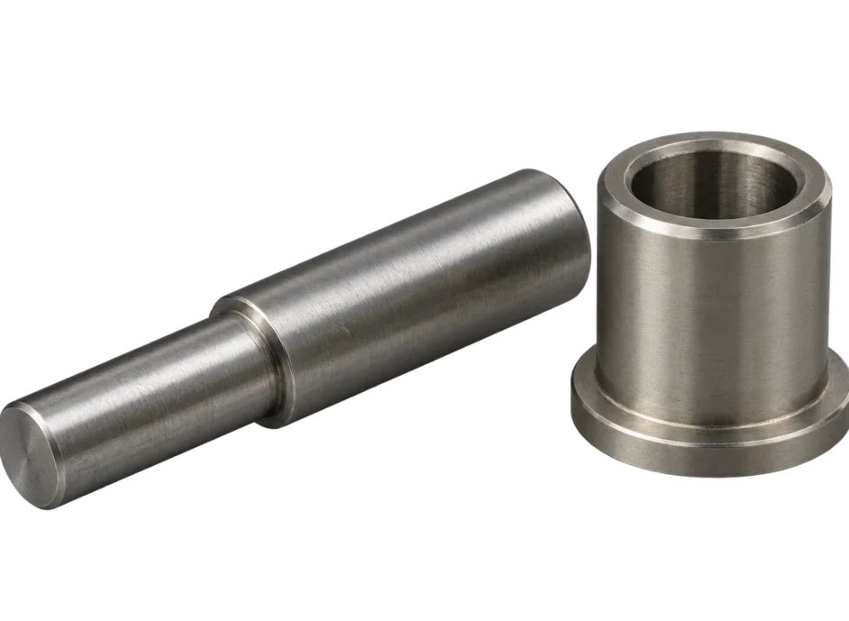
    PLATED INTERFACES / 단계 축과 플랜지 부시

    도금 공차 설계: 기능 치수·두께 분포·완성 검사

    정밀 부품의 표면처리는 재료의 기능을 바꾸면서 조립 공간도 바꿉니다. 외경은 커지고 내경은 작아지며, 마스킹 경계와 국부 성장까지 상대 부품의 움직임에…
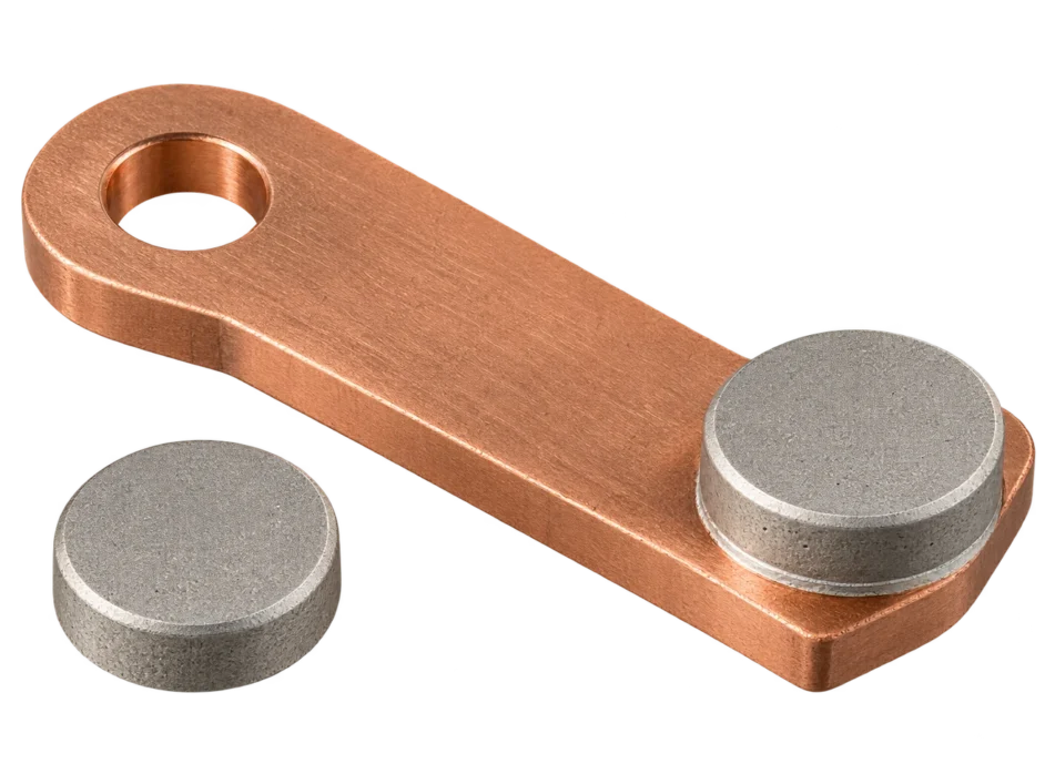
    AgW CONTACT / 구리 지지체에 접합된 복합 접점

    은·텅스텐 접점: 복합 조직·침투 제조·접합 품질의 설계

    두 상의 연결이 접점의 성능을 만듭니다.

    연결 준비 중입니다. 현재 전화 연결을 이용하실 수 있습니다.

    ID SOLUTECH
    LET’S TALK ENGINEERING

    무엇을
    도와드릴까요?

    아이디솔루텍의 제품과 제조 공정,
    기술자료에 대해 질문해 주세요.