OPTICAL FIXTURE MACHINING
광학기계용 SUS 플레이트·브래킷의 소량 정밀가공
OPTICAL FIXTURE MACHINING
기능 기준과 지지·클램핑, 원호·나사와 최종 검사를 연결합니다.
DATUM · SUPPORT · SLOT · ALIGNMENT
한두 개의 부품에서도 기준을 연결하면 결과를 검증할 수 있습니다.
광학기계용 SUS 플레이트와 원호형 장공 브래킷을 중심으로 소재·고정·다면 가공·나사·평면도·열적 안정성을 검토합니다. 최종 도면과 조립 조건을 기준으로 소량 맞춤 제작의 공정과 개별품 검사를 설계합니다.
FEATURE FAMILY / 접촉면·장공·홀·단차의 조합
광학 기능과 도면 기준
치수 합격을 잠금 후 정렬 유지와 연결합니다.
광학계의 지지 부품을 설계할 때는 먼저 움직이면 안 되는 위치와 방향을 정합니다. 플레이트의 높이 오차가 초점에 영향을 주는지, 브래킷의 회전이 광축을 바꾸는지에 따라 관리할 면과 홀도 달라집니다. 모든 외형 치수에 같은 정밀도를 요구하는 대신 성능에 민감한 연결 관계에 공차를 배정합니다.
볼트가 들어가는 공간은 체결 수단일 뿐 정밀한 위치를 정해 주는 것은 아닙니다. 핀이나 어깨가 위치를 정한다면 해당 형상을 검사하고, 조정 후 마찰로 위치를 유지한다면 잠금 과정과 외력에 대한 변위를 확인합니다. 제작 도면은 이 두 경우를 구분해 부품 검사와 조립 검사의 경계를 알려 주어야 합니다.
플레이트와 브래킷의 검증은 정렬에 민감한 연결부를 먼저 찾는 데서 시작합니다. 장공의 용도는 조립도와 상대물로 확정하고, 잠금 중 움직임·외력 후 복귀·온도 순환 후 위치를 서로 다른 결과로 기록합니다. 다른 광학 마운트의 안정성 수치를 이 부품의 보증값으로 사용하지 않습니다.
높이 변화가 성능에 전달되는 경로 · 기능 기준에서 측정한 면 위치
핀·어깨·접촉면의 구속 방향 · 재조립 시 위치 편차
조정 위치를 유지하는 하중 경로 · 체결 전후 이동과 외력 후 복귀
| 판단 대상 | 관리할 관계 | 확인할 증거 |
|---|---|---|
| 정렬에 민감한 면 | 높이 변화가 성능에 전달되는 경로 | 기능 기준에서 측정한 면 위치 |
| 위치 결정 형상 | 핀·어깨·접촉면의 구속 방향 | 재조립 시 위치 편차 |
| 잠금 구조 | 조정 위치를 유지하는 하중 경로 | 체결 전후 이동과 외력 후 복귀 |
정렬에 민감한 면
관리할 관계
높이 변화가 성능에 전달되는 경로
확인할 증거
기능 기준에서 측정한 면 위치
위치 결정 형상
관리할 관계
핀·어깨·접촉면의 구속 방향
확인할 증거
재조립 시 위치 편차
잠금 구조
관리할 관계
조정 위치를 유지하는 하중 경로
확인할 증거
체결 전후 이동과 외력 후 복귀
크기·형상·방향·위치를 같은 항목으로 취급하지 않습니다.
데이텀을 정하는 기준은 부품이 실제로 어디에 닿고 무엇으로 방향을 잡는가입니다. 넓은 면이 있어도 조립에서 세 개의 작은 패드만 접촉한다면 전체 면과 실제 지지 영역을 구분해야 합니다. 검사 장비의 자동 최적 맞춤 기능이 도면의 기준 순서를 바꾸지 않도록 정렬 방법을 함께 명시합니다.
홀 크기가 합격하면서 축 방향이나 위치가 어긋나는 경우가 있고, 두께가 일정해도 면 전체가 휘어 있을 수 있습니다. 크기 공차와 형상·방향·위치 요구는 이런 서로 다른 오차를 다룹니다. 적용하는 도면 체계와 판본을 정하고 중요한 관계에는 해석이 가능한 개별 요구를 부여해야 합니다.
가공자가 쓰는 좌표계와 검사자가 만드는 정렬을 도면의 기능 기준에 연결합니다. 가공용 임시 기준을 사용하더라도 최종 합격 판정은 지정된 기준 순서를 따라야 합니다. 실제 접촉 영역과 측정 가능한 영역이 다르면, 형상 완성 전에 검사 접근성과 필요한 보조 기준을 합의합니다.
실제 하중을 받는 영역과 기준 설정 · 접촉 영역·안착 방향 표시
두께와 평면도·평행도의 구분 · 특성별 독립 측정 결과
도면의 기준 우선순위 · 측정 좌표계와 평가 방식
크기·형상·방향·위치를 같은 항목으로 취급하지 않습니다.
측정 좌표계를 도면의 기능 기준에 연결합니다.
| 판단 대상 | 관리할 관계 | 확인할 증거 |
|---|---|---|
| 조립 접촉 | 실제 하중을 받는 영역과 기준 설정 | 접촉 영역·안착 방향 표시 |
| 기능 관계 | 두께와 평면도·평행도의 구분 | 특성별 독립 측정 결과 |
| 검사 정렬 | 도면의 기준 우선순위 | 측정 좌표계와 평가 방식 |
조립 접촉
관리할 관계
실제 하중을 받는 영역과 기준 설정
확인할 증거
접촉 영역·안착 방향 표시
기능 관계
관리할 관계
두께와 평면도·평행도의 구분
확인할 증거
특성별 독립 측정 결과
검사 정렬
관리할 관계
도면의 기준 우선순위
확인할 증거
측정 좌표계와 평가 방식
소재와 지지 경로
소재 이력·제거량·고정력·온도를 함께 기록합니다.
SUS는 하나의 가공 조건을 뜻하는 재질 이름이 아닙니다. 주문 강종과 열처리·냉간가공 이력, 소재 형태를 확인한 뒤 절삭 조건과 후처리를 검토해야 합니다. 특히 얇은 판으로 남길 부분은 소재의 초기 휨과 한쪽 면 제거량이 최종 형상에 영향을 주므로 입고 단계의 상태 기록이 중요합니다.
가공 중의 휨을 모두 잔류응력 탓으로 돌리면 지지나 온도 문제를 놓칠 수 있습니다. 클램프 힘을 바꿀 때 즉시 변하는 형상과, 온도가 내려가며 변하는 형상, 해제 후 남는 형상을 구분합니다. 이 비교에는 같은 측정 기준과 지지 조건이 필요하며 방치 시간만으로 응력 제거를 선언하지 않습니다.
응력 재분배, 탄성적인 고정 변형과 열변형은 같은 휨으로 보일 수 있습니다. 황삭 직후, 온도 안정 후, 고정 해제 후를 구분해 높이 분포를 비교하면 원인 분리에 도움이 됩니다. 강종과 공급 상태가 확인되지 않은 소재에 임의의 응력제거 열처리를 적용하지 않습니다.
강종·공급 이력과 초기 형상 · 성적서 및 초기 높이 지도
양면 절삭과 남은 비대칭 단면 · 황삭 단계별 형상 기록
힘 변화에 따른 탄성 변위 · 동일 지지에서의 전후 비교
소재 이력과 고정·온도 반응을 함께 기록합니다.
| 판단 대상 | 관리할 관계 | 확인할 증거 |
|---|---|---|
| 입고 소재 | 강종·공급 이력과 초기 형상 | 성적서 및 초기 높이 지도 |
| 제거 계획 | 양면 절삭과 남은 비대칭 단면 | 황삭 단계별 형상 기록 |
| 고정 반응 | 힘 변화에 따른 탄성 변위 | 동일 지지에서의 전후 비교 |
| 열 반응 | 냉각 시간과 온도 구배 | 부품 온도 및 안정 후 치수 |
입고 소재
관리할 관계
강종·공급 이력과 초기 형상
확인할 증거
성적서 및 초기 높이 지도
제거 계획
관리할 관계
양면 절삭과 남은 비대칭 단면
확인할 증거
황삭 단계별 형상 기록
고정 반응
관리할 관계
힘 변화에 따른 탄성 변위
확인할 증거
동일 지지에서의 전후 비교
열 반응
관리할 관계
냉각 시간과 온도 구배
확인할 증거
부품 온도 및 안정 후 치수
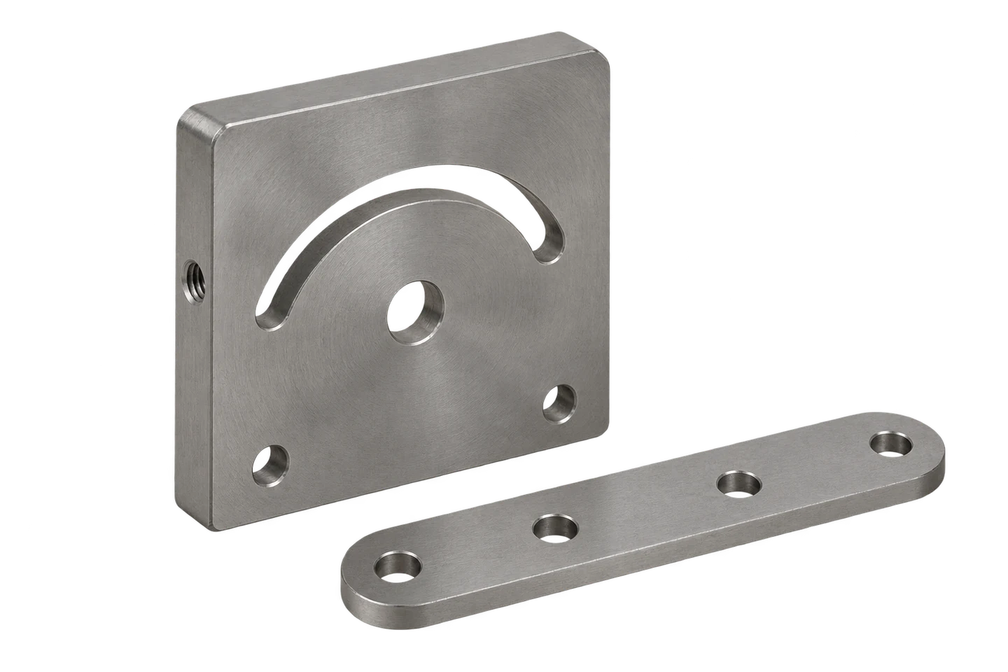
CURVED SLOT / 관통 장공과 중심 홀의 관계
04 / SUPPORT AND CLAMP
클램프 힘을 지지점으로 전달하는 구조를 만듭니다.
위치 결정자는 부품의 좌표를 만들고 클램프는 그 좌표에서 벗어나지 않도록 힘을 가합니다. 절삭력의 방향이 바뀌는 슬롯과 외곽 가공에서는 미끄럼뿐 아니라 들림과 회전도 고려해야 합니다. 가능한 하중을 단단한 스토퍼와 지지로 받아 내고, 마찰만으로 모든 방향을 억제하는 배치를 피합니다.
얇은 영역을 누를 때는 누름점 아래로 힘이 전달되는지를 살펴야 합니다. 지지가 멀리 떨어져 있으면 부품을 휘게 만든 채 평면을 가공할 수 있습니다. 가공 후 클램프를 푸는 시험과 재안착 시험을 통해 지지 위치·고정력·표면 청결이 결과에 미치는 영향을 구분합니다.
3-2-1 위치 결정은 강체의 구속을 설명하며 얇은 판의 변형을 자동으로 해결하지 않습니다. 보조 지지는 이미 결정된 부품 위치를 밀어 올리지 않게 조정하고, 클램프 접촉부 아래의 힘 전달을 확인합니다. 재안착 시험은 지그 자체의 반복성과 칩·버에 의한 들뜸을 함께 확인하는 기회입니다.
클램프 힘을 지지점으로 전달하는 구조를 만듭니다.
| 판단 대상 | 관리할 관계 | 확인할 증거 |
|---|---|---|
| 좌표 설정 | 여섯 강체 자유도의 제한 | 위치 결정 접촉의 역할 |
| 힘 전달 | 누름점과 받침 사이 거리 | 고정 전후 변위 |
| 절삭 반력 | 들림·미끄럼·회전의 방향 | 스토퍼와 클램프 배치 |
| 다시 놓기 | 칩·버·접촉의 재현성 | 재안착 높이와 위치 |
좌표 설정
관리할 관계
여섯 강체 자유도의 제한
확인할 증거
위치 결정 접촉의 역할
힘 전달
관리할 관계
누름점과 받침 사이 거리
확인할 증거
고정 전후 변위
절삭 반력
관리할 관계
들림·미끄럼·회전의 방향
확인할 증거
스토퍼와 클램프 배치
다시 놓기
관리할 관계
칩·버·접촉의 재현성
확인할 증거
재안착 높이와 위치
암과 장공 볼트는 같은 피벗 중심을 공유합니다. 볼트 중심이 실제 원호를 따라 움직입니다.
기준 전달과 안정된 절삭
홀·장공·측면 나사의 관계를 공정 순서에 반영합니다.
다면 부품의 공정표에는 가공할 면뿐 아니라 다음 공정으로 넘길 기준을 적습니다. 첫 고정에서 완성한 면이 두 번째 고정의 안착면이라면 버 제거와 청결 확인이 기준 전달의 일부가 됩니다. 나사나 장공을 일찍 가공해 지지 단면이 줄어드는지, 나중에 가공해 접근이 막히는지도 비교합니다.
장비의 축 수보다 중요한 것은 필요한 형상 관계를 얼마나 일관되게 유지하는가입니다. 회전축을 사용해도 회전 중심 보정과 공구 길이, 지그 간섭을 확인해야 합니다. 소량 제작에서는 최종 두께나 나사처럼 복구가 어려운 작업 전에 남은 여유와 기준 상태를 확인하는 중간 점검이 효과적입니다.
공정을 나눌 때는 각 고정에서 남기는 기준과 다음 고정에서 읽는 기준을 한 쌍으로 표시합니다. 측면 나사를 가공하기 위해 부품을 세웠다면 안착면 보호와 회전 방향도 확인해야 합니다. 같은 기계의 프로빙 결과와 독립된 최종 검사를 함께 사용하면 원점 확인과 제품 검증의 역할이 선명해집니다.
후속 공정에 사용할 접촉면 · 안착 가능 영역과 여유
원점과 기준 방향의 전달 · 설정값·프로빙 결과
장공과 외곽 제거의 순서 · 남은 연결부와 지지
다음 공정에서 읽을 기준을 앞 공정에서 준비합니다.
| 판단 대상 | 관리할 관계 | 확인할 증거 |
|---|---|---|
| 첫 기준 | 후속 공정에 사용할 접촉면 | 안착 가능 영역과 여유 |
| 회전·재고정 | 원점과 기준 방향의 전달 | 설정값·프로빙 결과 |
| 강성 변화 | 장공과 외곽 제거의 순서 | 남은 연결부와 지지 |
| 중간 점검 | 복구가 어려운 단계의 진입 조건 | 두께·위치·잔여 여유 |
첫 기준
관리할 관계
후속 공정에 사용할 접촉면
확인할 증거
안착 가능 영역과 여유
회전·재고정
관리할 관계
원점과 기준 방향의 전달
확인할 증거
설정값·프로빙 결과
강성 변화
관리할 관계
장공과 외곽 제거의 순서
확인할 증거
남은 연결부와 지지
중간 점검
관리할 관계
복구가 어려운 단계의 진입 조건
확인할 증거
두께·위치·잔여 여유
회전수 하나보다 날끝·물림·돌출·배출의 조합을 봅니다.
절삭날이 실제로 만드는 칩 두께는 프로그램의 날당 이송과 항상 같지 않습니다. 공구가 물리는 폭과 진입 각도, 코너 형상이 달라지면 한 날이 받는 부하도 달라집니다. 특히 오스테나이트계 소재는 얕게 문지르는 조건과 응착을 구분해 관찰하고, 정확한 강종에 맞는 공구 권장 범위에서 조정합니다.
길게 돌출한 공구나 지지가 약한 부품은 평균 치수가 맞아도 벽면 테이퍼와 진동 무늬를 남길 수 있습니다. 반복 무늬가 보이면 정적 처짐과 재생 채터의 가능성을 나눠 봅니다. 냉각 공급도 유량만 확인하지 말고 절삭부 도달과 칩 배출, 날끝의 열적 반복 조건을 함께 평가합니다.
공구 조건표는 정확한 강종과 가공 모드가 일치할 때 시작점이 됩니다. 공구가 문지르는지, 칩이 다시 잘리는지, 단차 부근에서 물림이 갑자기 커지는지를 구분한 뒤 조건을 조정합니다. 마모 위치·절삭음·실제 치수 변화가 같은 방향을 가리키는지 확인하고 한 번에 바꾼 변수를 기록합니다.
이송·물림·날끝의 조합 · 칩 형태와 응착 흔적
돌출·홀더·런아웃 · 높이별 벽 위치
회전수와 물림의 상호작용 · 진동·소음과 반복 무늬
직선과 코너 구간의 칩·표면 변화를 비교합니다.
| 판단 대상 | 관리할 관계 | 확인할 증거 |
|---|---|---|
| 칩 생성 | 이송·물림·날끝의 조합 | 칩 형태와 응착 흔적 |
| 공구계 강성 | 돌출·홀더·런아웃 | 높이별 벽 위치 |
| 동적 반응 | 회전수와 물림의 상호작용 | 진동·소음과 반복 무늬 |
| 공급·배출 | 절삭부 도달과 재절삭 | 잔류 칩·공구 손상 |
칩 생성
관리할 관계
이송·물림·날끝의 조합
확인할 증거
칩 형태와 응착 흔적
공구계 강성
관리할 관계
돌출·홀더·런아웃
확인할 증거
높이별 벽 위치
동적 반응
관리할 관계
회전수와 물림의 상호작용
확인할 증거
진동·소음과 반복 무늬
공급·배출
관리할 관계
절삭부 도달과 재절삭
확인할 증거
잔류 칩·공구 손상
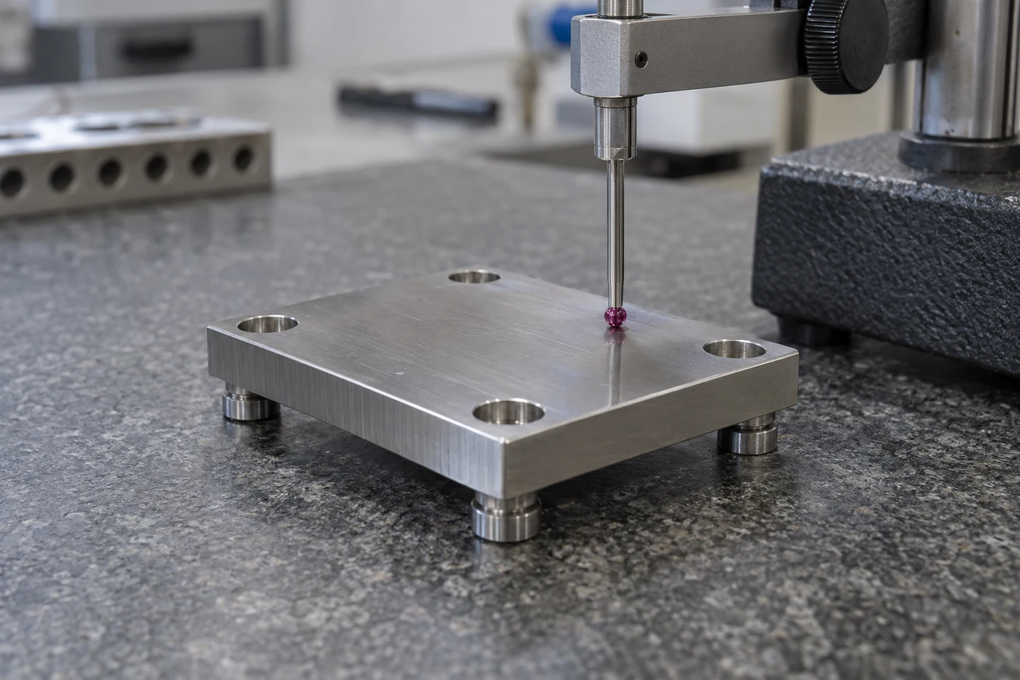
SURFACE INSPECTION / 지지된 플레이트의 기능면 확인
평면·외곽·원호 형상
광택·거칠기·평면도는 서로 다른 결과입니다.
가공면의 밝은 무늬는 회전 공구가 지나간 흔적이지만 정량적인 정밀도 표시는 아닙니다. 조립 접촉에 필요한 면 전체의 형상과 국부적인 미세 요철을 다른 검사로 확인합니다. 광로에 노출되는 표면은 반사와 산란 요구까지 따로 정의해야 하며, 구조부품의 모든 면을 광학 연마면으로 취급할 이유는 없습니다.
외곽과 단차는 공구 접근성을 함께 설계해야 합니다. 좁은 오목 코너는 물림을 급격하게 늘리고 깊은 벽은 긴 날과 돌출을 요구할 수 있습니다. 허용 가능한 내측 반경·릴리프·가공 방향을 정한 뒤 높이별 벽 형상과 바닥 관계를 확인하면 단순한 지름 보정으로 해결되지 않는 오차를 찾을 수 있습니다.
광학계 주변의 기계면은 지지·접촉·산란 억제 중 어느 역할을 하는지 구분해야 합니다. 가공 흔적을 없애기 위한 연마가 오히려 기준면이나 모서리를 바꿀 수 있으므로, 마감 요구는 측정 특성과 연결합니다. 벽의 위·아래 치수가 다르면 평균 보정값보다 공구 처짐과 지지를 먼저 확인합니다.
전체 휨과 국부 돌출 · 합의한 지지의 형상 측정
방향·필터·평가 길이 · 조건이 명시된 거칠기
공구 반경과 물림 변화 · 코너·직선 전이부
광택·거칠기·평면도는 서로 다른 결과입니다.
외관 무늬와 정량적인 형상 검사를 분리합니다.
| 판단 대상 | 관리할 관계 | 확인할 증거 |
|---|---|---|
| 접촉 평면 | 전체 휨과 국부 돌출 | 합의한 지지의 형상 측정 |
| 표면 조직 | 방향·필터·평가 길이 | 조건이 명시된 거칠기 |
| 내측 코너 | 공구 반경과 물림 변화 | 코너·직선 전이부 |
| 단차 벽 | 깊이와 공구 처짐 | 상·하부 치수 및 방향 |
접촉 평면
관리할 관계
전체 휨과 국부 돌출
확인할 증거
합의한 지지의 형상 측정
표면 조직
관리할 관계
방향·필터·평가 길이
확인할 증거
조건이 명시된 거칠기
내측 코너
관리할 관계
공구 반경과 물림 변화
확인할 증거
코너·직선 전이부
단차 벽
관리할 관계
깊이와 공구 처짐
확인할 증거
상·하부 치수 및 방향
공구 끝면을 실제 상면에 맞춘 정적 공정 상태입니다. 칩 생성이나 연속 제거를 재현하지 않습니다.
형상 기준과 공구 중심 이송을 함께 확인합니다.
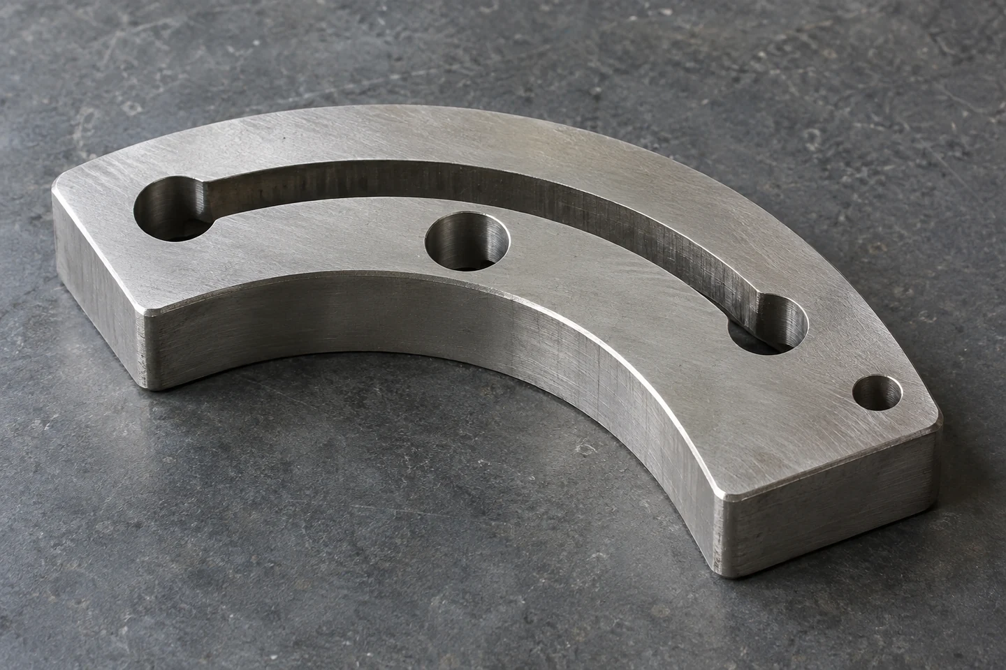
원호형 관통 장공은 폭 외에도 원의 중심, 반지름과 양쪽 끝단의 위치가 기능에 관여합니다. 회전 중심이 별도의 원형 홀로 정해지는 설계라면 두 중심의 관계를 기준 체계에서 평가합니다. 조정 기능이 없는 장공이라면 같은 검사 항목을 무조건 요구하지 말고 실제 통과·간섭 조건에 맞게 범위를 정합니다.
슬롯 전체 폭을 한 번에 물리는 방식과 작은 공구로 양쪽 벽을 나누어 정삭하는 방식은 부하와 보정 가능성이 다릅니다. 내측 벽을 따라 움직이는 공구 중심은 완성 윤곽보다 작은 원을 지나므로 이송 기준도 확인해야 합니다. 관통 직전에는 얇게 남은 바닥과 떨어지는 칩이 지지와 표면에 미치는 영향을 살펴봅니다.
원호 가공의 설명 예로 R=20 mm, r=3 mm, 완성 윤곽 이송 200 mm/min이면 내측 원호의 공구 중심 이송은 170 mm/min입니다. 이 값은 원주 길이 비율의 계산이며 권장 절삭 조건이 아닙니다. CAM 또는 제어기가 이미 보정하는지 확인하고 바깥쪽 볼록 원호에는 별도의 반경 관계를 적용합니다.
R: 완성 내측 원호의 반경(mm), r: 공구 반경(mm), vcontour: 해당 원호 윤곽 이송(mm/min), vcenter: 공구 중심 이송(mm/min). 0 < r < R인 동일 각속도의 단순 내측 원호에 적용합니다. 공구 물림·실제 칩 두께·제어기 보정은 별도 확인합니다.
윤곽 이송과 공구 중심 이송의 기준을 확인합니다.
| 판단 대상 | 관리할 관계 | 확인할 증거 |
|---|---|---|
| 중심 관계 | 원형 홀과 원호 중심 | 동일 기준에서의 위치 |
| 통과 폭 | 양쪽 벽과 끝단 반경 | 각도별 폭·윤곽 |
| 이송 기준 | 공구 중심과 접촉 윤곽 | CAM·제어기 설정 |
| 관통 조건 | 잔여 바닥과 칩 이동 | 하부 지지·출구 모서리 |
중심 관계
관리할 관계
원형 홀과 원호 중심
확인할 증거
동일 기준에서의 위치
통과 폭
관리할 관계
양쪽 벽과 끝단 반경
확인할 증거
각도별 폭·윤곽
이송 기준
관리할 관계
공구 중심과 접촉 윤곽
확인할 증거
CAM·제어기 설정
관통 조건
관리할 관계
잔여 바닥과 칩 이동
확인할 증거
하부 지지·출구 모서리
나사와 최종 표면 상태
밑구멍 깊이와 완전산 깊이를 구분합니다.
홀은 체결 볼트의 통로인지 위치 결정 형상인지에 따라 요구가 달라집니다. 리머로 지름을 맞추더라도 처음 만들어진 홀의 위치 오류가 자동으로 사라지는 것은 아닙니다. 자리파기 바닥이 체결 하중을 받는다면 깊이뿐 아니라 접촉 면과 홀 축의 관계를 함께 정해야 합니다.
측면 암나사는 공구가 도달하는 길이와 완전한 산을 형성하는 길이를 구분합니다. 막힌 홀에는 드릴 선단과 탭의 리드, 칩이 머무를 공간을 포함한 여유가 필요합니다. 최종 게이지 검사 전에 입구 버와 잔류 칩을 제거하고, 게이지의 통과와 실제 안착·뒤쪽 간섭은 다른 항목으로 확인합니다.
작은 측면 나사는 공구 접근과 배출 공간이 동시에 제한될 수 있습니다. 나사 호칭과 공차, 실제 완전산 길이, 관통 뒤 간섭 공간을 도면에 연결하고 최종 마감 후 검사합니다. 체결 중 걸림이 생기면 토크를 높이기 전에 버·칩·축 불일치와 응착 손상의 가능성을 구분합니다.
밑구멍 깊이와 완전산 깊이를 구분합니다.
홀 크기와 축 위치, 나사 물림을 각각 확인합니다.
| 판단 대상 | 관리할 관계 | 확인할 증거 |
|---|---|---|
| 홀의 용도 | 체결 통로와 위치 결정 | 지름·위치·축 요구 |
| 자리파기 | 하중 받는 바닥과 축 | 깊이 및 접촉 상태 |
| 완전산 | 공구 리드와 사용 물림 | 도면 깊이·게이지 절차 |
| 조립 공간 | 관통 뒤 돌출과 상대물 | 실제 체결·간섭 확인 |
홀의 용도
관리할 관계
체결 통로와 위치 결정
확인할 증거
지름·위치·축 요구
자리파기
관리할 관계
하중 받는 바닥과 축
확인할 증거
깊이 및 접촉 상태
완전산
관리할 관계
공구 리드와 사용 물림
확인할 증거
도면 깊이·게이지 절차
조립 공간
관리할 관계
관통 뒤 돌출과 상대물
확인할 증거
실제 체결·간섭 확인
버 제거와 열 안정화를 검사 조건에 포함합니다.
버는 조립 시 지지점을 바꾸거나 떨어져 나와 광학계 주변의 입자가 될 수 있습니다. 그렇다고 모든 모서리를 크게 연마하면 안착 폭과 장공 끝단, 나사 물림이 변합니다. 기능 모서리에 허용되는 형상을 정하고 접근 가능한 제거 방법을 공정에 넣어 마감 후 다시 확인합니다.
세척·표면처리·건조를 거친 최종 상태가 검사와 포장의 기준이 되어야 합니다. 잔류액이 숨는 나사와 단차는 취급 과정까지 고려하고, 열처리나 화학 처리를 추가할 때는 정확한 소재의 적합성을 검토합니다. 검사 온도와 사용 온도가 다르면 길이 보정의 문제와 조립체의 열변형 문제를 나눠 평가합니다.
세척한 부품도 손으로 오래 잡거나 따뜻한 공정에서 바로 옮기면 검사 중 온도가 변할 수 있습니다. 부품·측정기·지지대의 상태를 함께 확인하고 안정화 시간을 무조건 고정 숫자로 정하지 않습니다. 납품 포장은 기능면과 나사 내부의 재오염 및 서로 부딪히는 손상을 막도록 정합니다.
버 제거와 형상 보존 · 마감 후 폭·깊이
나사·장공·단차의 잔류물 · 세척·헹굼·건조 결과
강종과 표면 요구 · 처리 조건 및 재검사
세척 이후의 온도와 재오염도 관리합니다.
| 판단 대상 | 관리할 관계 | 확인할 증거 |
|---|---|---|
| 기능 모서리 | 버 제거와 형상 보존 | 마감 후 폭·깊이 |
| 오염 취약부 | 나사·장공·단차의 잔류물 | 세척·헹굼·건조 결과 |
| 추가 처리 | 강종과 표면 요구 | 처리 조건 및 재검사 |
| 온도 상태 | 기준 치수와 사용 변위 | 측정 온도·조립 열시험 |
기능 모서리
관리할 관계
버 제거와 형상 보존
확인할 증거
마감 후 폭·깊이
오염 취약부
관리할 관계
나사·장공·단차의 잔류물
확인할 증거
세척·헹굼·건조 결과
추가 처리
관리할 관계
강종과 표면 요구
확인할 증거
처리 조건 및 재검사
온도 상태
관리할 관계
기준 치수와 사용 변위
확인할 증거
측정 온도·조립 열시험
개별 검사와 제작 조건
부품 식별과 측정 조건을 결과에 연결합니다.
검사 계획은 사용 장비의 목록보다 확인할 특성의 정의에서 출발합니다. 면의 형상에는 적절한 점 분포가 필요하고 홀 위치에는 기능 기준에 맞는 정렬이 필요합니다. 두께를 마이크로미터 한 곳에서 읽은 값이나 게이지 한 개의 결과로 다른 특성까지 합격이라고 확대 해석하지 않습니다.
한두 개를 제작해도 검사 시점과 식별은 명확해야 합니다. 황삭 후 측정은 남은 여유를 판단하고 최종 측정은 납품 요구를 판단합니다. 재측정에서 값이 달라지면 부품의 변화인지 지지·온도·측정 반복성인지 먼저 분리하고, 공차 경계의 판정에는 사전에 합의한 규칙을 사용합니다.
초소량 제작에서는 개별 부품의 상태를 충실히 남기는 편이 작은 표본에서 공정능력 지수를 계산하는 것보다 유용합니다. 동일한 부품을 여러 번 측정한 결과는 측정 반복성의 정보이며 여러 생산 로트의 변동을 대신하지 않습니다. 도면 개정, 지지 조건, 판정 규칙과 재검사 이력을 함께 보존합니다.
측정점과 평가 영역 · 평면·윤곽의 분포 데이터
기능 기준에서의 정렬 · 홀·면의 위치와 방향
부품과 공정 단계의 연결 · 도면 개정·검사 이력
부품 식별과 측정 조건을 결과에 연결합니다.
측정 특성별로 지지와 평가 방법을 지정합니다.
| 판단 대상 | 관리할 관계 | 확인할 증거 |
|---|---|---|
| 형상 평가 | 측정점과 평가 영역 | 평면·윤곽의 분포 데이터 |
| 관계 평가 | 기능 기준에서의 정렬 | 홀·면의 위치와 방향 |
| 개별 추적 | 부품과 공정 단계의 연결 | 도면 개정·검사 이력 |
| 판정 신뢰성 | 불확도와 경계값 | 교정·반복성·판정 규칙 |
형상 평가
관리할 관계
측정점과 평가 영역
확인할 증거
평면·윤곽의 분포 데이터
관계 평가
관리할 관계
기능 기준에서의 정렬
확인할 증거
홀·면의 위치와 방향
개별 추적
관리할 관계
부품과 공정 단계의 연결
확인할 증거
도면 개정·검사 이력
판정 신뢰성
관리할 관계
불확도와 경계값
확인할 증거
교정·반복성·판정 규칙
수정한 특성과 영향받는 기능을 함께 재검사합니다.
불량을 진단할 때는 처음 차이가 발생한 시점을 찾습니다. 풀었을 때만 휘면 고정과 잔류응력 경로를 비교하고, 잠금 후에만 광축이 움직이면 접촉과 체결 순서를 확인합니다. 표면의 반복 무늬와 나사 걸림 역시 서로 다른 현상이므로 한 가지 보정으로 모두 해결하려 하지 않습니다.
의뢰 단계에서 빠진 요구는 제조 과정의 추측으로 채워질 가능성이 큽니다. 강종·공급 상태, 도면과 3D의 개정, 기능 공차, 모서리·나사·표면·청정도를 정리하고 수량과 검사 범위를 연결합니다. 수정품은 변경한 치수뿐 아니라 영향을 받는 기준과 조립 기능까지 확인한 뒤 납품합니다.
소량 의뢰에서는 재질·공급 상태, 기준과 공차, 원호형 장공의 용도, 나사 규격, 마감과 검사 범위를 먼저 확정합니다. 수정이 필요하면 남은 가공 여유와 기능면 영향까지 검토합니다. 최종 납품 조건은 자유 상태 치수와 필요한 조립 검증을 구분해 적어 다음 제작에도 같은 판단을 적용할 수 있게 합니다.
가공·해제·마감·체결의 구분 · 단계별 전후 기록
지지·열·절삭·마찰 · 한 변수씩 확인한 결과
남은 여유와 기능 영향 · 수정 도면·재검사 범위
증상이 발생한 공정 구간부터 원인을 좁힙니다.
| 판단 대상 | 관리할 관계 | 확인할 증거 |
|---|---|---|
| 증상 발생점 | 가공·해제·마감·체결의 구분 | 단계별 전후 기록 |
| 원인 분리 | 지지·열·절삭·마찰 | 한 변수씩 확인한 결과 |
| 변경 승인 | 남은 여유와 기능 영향 | 수정 도면·재검사 범위 |
| 납품 명세 | 수량·품질·기록 수준 | 최종 상태와 식별 자료 |
증상 발생점
관리할 관계
가공·해제·마감·체결의 구분
확인할 증거
단계별 전후 기록
원인 분리
관리할 관계
지지·열·절삭·마찰
확인할 증거
한 변수씩 확인한 결과
변경 승인
관리할 관계
남은 여유와 기능 영향
확인할 증거
수정 도면·재검사 범위
납품 명세
관리할 관계
수량·품질·기록 수준
확인할 증거
최종 상태와 식별 자료
강종·공급 상태, 도면과 기능 기준, 장공·나사 요구, 마감·청정도와 개별 검사 범위를 보내주세요.
Provide grade and condition, drawing and functional references, slot and thread requirements, finish, cleanliness and individual inspection scope.
OPTICAL FIXTURE MACHINING
Connect functional references, support and clamping with slots, threads and final inspection.
DATUM · SUPPORT · SLOT · ALIGNMENT
ENGLISH EDITION
Connect references from stock to assembly.
A clear chain of references makes even a one- or two-piece order verifiable.
Using SUS plates and curved-slot brackets for optical instruments, connect stock, workholding, multiple setups, threads, flatness and thermal stability. Plan machining and individual-part inspection against the final drawing and assembly conditions.
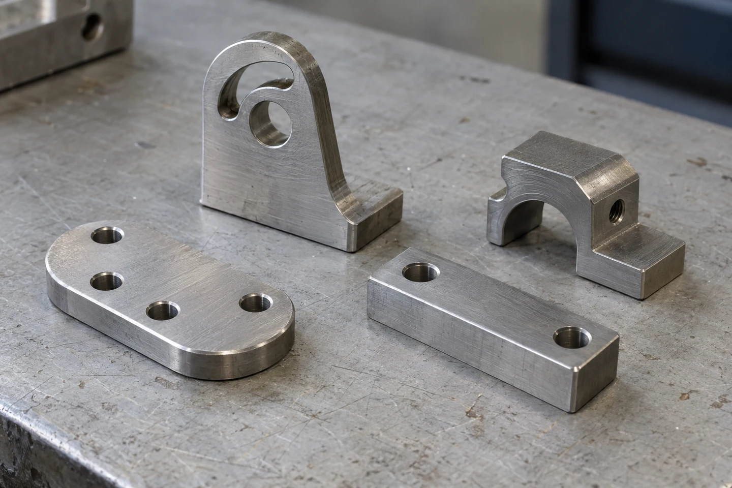
FEATURE FAMILY / Contact faces, slots, holes and shoulders
Optical function and drawing references
Connect dimensional conformance with alignment after locking.
Start an optical support design by identifying the positions and directions that must remain stable. A plate-height error affecting focus and a bracket rotation affecting beam alignment call for different controlled faces and holes. Allocate tolerances to sensitive relationships instead of assigning identical precision to every outside dimension.
Clearance for a bolt provides fastening access but does not inherently locate a component precisely. Inspect a locating pin or shoulder when it establishes position; check locking motion and load response when friction retains an adjusted position. The drawing should distinguish these cases and define where component inspection ends and assembly verification begins.
Begin by identifying interfaces that strongly affect alignment. Establish the slot function from the assembly and mating part, then record movement during locking, recovery after loading and position after temperature cycling as distinct results. Stability values from another optical mount do not become guarantees for this part.
Path from height change to optical performance. Face position in the functional reference system
Constraint from pins, shoulders or contact faces. Position variation after reassembly
Load path retaining the adjusted position. Shift during locking and recovery after loading
| Decision item | Relationship to control | Evidence to examine |
|---|---|---|
| Alignment-sensitive face | Path from height change to optical performance | Face position in the functional reference system |
| Locating feature | Constraint from pins, shoulders or contact faces | Position variation after reassembly |
| Locking feature | Load path retaining the adjusted position | Shift during locking and recovery after loading |
Alignment-sensitive face
Relationship to control
Path from height change to optical performance
Evidence to examine
Face position in the functional reference system
Locating feature
Relationship to control
Constraint from pins, shoulders or contact faces
Evidence to examine
Position variation after reassembly
Locking feature
Relationship to control
Load path retaining the adjusted position
Evidence to examine
Shift during locking and recovery after loading
Treat size, form, orientation and location as distinct characteristics.
Select datums from the actual contacts and locating directions in the assembly. A broad face may be supported only on three small pads, so distinguish the entire face from its functional support region. Specify the inspection alignment so an automatic best fit does not replace the drawing’s intended reference sequence.
A hole can meet size limits while its axis or location is wrong, and a part of uniform thickness can still be bowed. Size, form, orientation and location requirements address these different errors. Establish the drawing system and edition, then give important relationships specific requirements that can be interpreted and inspected.
Connect machine coordinates and inspection alignment to the functional drawing references. Temporary machining references can be useful, but final acceptance must follow the specified datum sequence. If the actual contact region differs from the accessible measurement region, agree inspection access and auxiliary references before completing the geometry.
Loaded region and datum establishment. Defined contact area and seating direction
Thickness versus flatness and parallelism. Separate results for each characteristic
Drawing datum precedence. Measurement coordinate system and evaluation method
Treat size, form, orientation and location as distinct characteristics.
Connect the measurement coordinate system to the functional datums.
| Decision item | Relationship to control | Evidence to examine |
|---|---|---|
| Assembly contact | Loaded region and datum establishment | Defined contact area and seating direction |
| Functional relationship | Thickness versus flatness and parallelism | Separate results for each characteristic |
| Inspection alignment | Drawing datum precedence | Measurement coordinate system and evaluation method |
Assembly contact
Relationship to control
Loaded region and datum establishment
Evidence to examine
Defined contact area and seating direction
Functional relationship
Relationship to control
Thickness versus flatness and parallelism
Evidence to examine
Separate results for each characteristic
Inspection alignment
Relationship to control
Drawing datum precedence
Evidence to examine
Measurement coordinate system and evaluation method
Stock and support paths
Record stock history, removal, clamping and temperature.
SUS does not identify one universal machining condition. Establish the ordered grade, heat-treatment and cold-work history and stock form before selecting cutting conditions or finishing. For regions left as thin plates, incoming bow and one-sided removal can affect final shape, making an initial stock-condition record useful.
Attributing every machining distortion to residual stress can conceal support or temperature problems. Distinguish immediate changes with clamp force, changes during cooling and shape that remains after release. Compare them using consistent references and supports; elapsed resting time alone does not demonstrate stress removal.
Residual-stress redistribution, elastic clamping deflection and thermal distortion can produce similar-looking bow. Compare height patterns immediately after roughing, after temperature stabilization and after release to distinguish mechanisms. Do not prescribe a stress-relief heat treatment before the alloy and supply condition are established.
Grade, supply history and initial form. Certificate and initial height map
Two-sided cutting and remaining asymmetry. Shape records at roughing stages
Elastic displacement as force changes. Before/after comparison on matching supports
Record stock history together with clamp and temperature response.
| Decision item | Relationship to control | Evidence to examine |
|---|---|---|
| Incoming stock | Grade, supply history and initial form | Certificate and initial height map |
| Removal plan | Two-sided cutting and remaining asymmetry | Shape records at roughing stages |
| Clamp response | Elastic displacement as force changes | Before/after comparison on matching supports |
| Thermal response | Cooling history and temperature gradients | Part temperature and stabilized dimensions |
Incoming stock
Relationship to control
Grade, supply history and initial form
Evidence to examine
Certificate and initial height map
Removal plan
Relationship to control
Two-sided cutting and remaining asymmetry
Evidence to examine
Shape records at roughing stages
Clamp response
Relationship to control
Elastic displacement as force changes
Evidence to examine
Before/after comparison on matching supports
Thermal response
Relationship to control
Cooling history and temperature gradients
Evidence to examine
Part temperature and stabilized dimensions
CURVED SLOT / Through slot and center-hole relationship
04 / SUPPORT AND CLAMP
Provide a supported path for the clamping force.
Locators establish coordinates, while clamps apply forces that retain the work at those coordinates. Slot and contour milling change force direction, requiring checks for lifting and rotation as well as sliding. Where practical, react loads through positive stops and supports instead of relying on friction to resist every direction.
When clamping a thin region, examine how the force reaches the support below it. Distant support can cause a face to be machined while the part is elastically bent. Release and relocation trials help distinguish the effects of support position, clamp force and contact cleanliness.
The 3-2-1 principle explains rigid-body constraint; it does not automatically prevent a thin plate from bending. Adjust supplementary supports without lifting the located part and check the load path beneath each clamp. A relocation trial checks fixture repeatability together with lift caused by chips or burrs.
Provide a supported path for the clamping force.
| Decision item | Relationship to control | Evidence to examine |
|---|---|---|
| Coordinate location | Constraint of six rigid-body freedoms | Role of each locating contact |
| Force transfer | Distance between clamp and support | Displacement before and after clamping |
| Cutting reaction | Directions of lift, slip and rotation | Stop and clamp arrangement |
| Relocation | Repeatable contact free of chips and burrs | Reseated height and position |
Coordinate location
Relationship to control
Constraint of six rigid-body freedoms
Evidence to examine
Role of each locating contact
Force transfer
Relationship to control
Distance between clamp and support
Evidence to examine
Displacement before and after clamping
Cutting reaction
Relationship to control
Directions of lift, slip and rotation
Evidence to examine
Stop and clamp arrangement
Relocation
Relationship to control
Repeatable contact free of chips and burrs
Evidence to examine
Reseated height and position
The arm and slot fastener share the same pivot center. The bolt center follows the actual circular slot.
Datum transfer and stable cutting
Plan the relationships among holes, slots and side threads.
A multi-face process plan should identify both the surface being machined and the reference passed to the next setup. If a finished face becomes the next seating reference, deburring and cleaning are part of datum transfer. Compare early machining that weakens support sections with late machining that may obstruct access.
The key issue is maintaining feature relationships consistently, rather than the number of machine axes alone. Rotary-axis machining still needs verified pivot calibration, tool length and fixture clearance. In small batches, an intermediate allowance and reference check is valuable before irreversible features such as final thickness or threads are completed.
For each setup, pair the reference being created with the reference used in the next setup. When standing a part upright to machine a side thread, check seating-face protection and orientation as well. Combining on-machine probing with independent final inspection separates origin setting from product verification.
Contact surface for later operations. Usable seating region and allowance
Transfer of origin and reference direction. Setup values and probing results
Sequence of slot and contour removal. Remaining ligaments and support
Prepare the next operation’s reference in the preceding operation.
| Decision item | Relationship to control | Evidence to examine |
|---|---|---|
| Initial reference | Contact surface for later operations | Usable seating region and allowance |
| Rotation or resetting | Transfer of origin and reference direction | Setup values and probing results |
| Changing stiffness | Sequence of slot and contour removal | Remaining ligaments and support |
| Intermediate check | Entry condition for irreversible operations | Thickness, location and remaining stock |
Initial reference
Relationship to control
Contact surface for later operations
Evidence to examine
Usable seating region and allowance
Rotation or resetting
Relationship to control
Transfer of origin and reference direction
Evidence to examine
Setup values and probing results
Changing stiffness
Relationship to control
Sequence of slot and contour removal
Evidence to examine
Remaining ligaments and support
Intermediate check
Relationship to control
Entry condition for irreversible operations
Evidence to examine
Thickness, location and remaining stock
Review edge, engagement, overhang and evacuation together.
Actual chip thickness is not always identical to programmed feed per tooth. Engagement width, entry angle and corner geometry alter the load on each edge. For austenitic grades in particular, distinguish rubbing from adhesive buildup and adjust within guidance for the exact material and tool.
Long tool overhang or weak workpiece support can leave taper and vibration marks even when an average dimension is correct. A repeating pattern calls for distinguishing static deflection from possible regenerative chatter. Evaluate coolant access, chip evacuation and thermal cycling at the edge as well as nominal flow.
A tooling table provides a starting point only when grade and operation match. Distinguish rubbing, chip recutting and sudden engagement growth near a shoulder before changing settings. Check whether wear location, cutting sound and dimensional drift support the same diagnosis, and record which variables changed in each trial.
Feed, engagement and edge condition. Chip form and adhesion evidence
Overhang, holder and runout. Wall position at different heights
Interaction of speed and engagement. Vibration, sound and repeating marks
Compare chips and surfaces in straight and corner segments.
| Decision item | Relationship to control | Evidence to examine |
|---|---|---|
| Chip generation | Feed, engagement and edge condition | Chip form and adhesion evidence |
| Tool-system stiffness | Overhang, holder and runout | Wall position at different heights |
| Dynamic response | Interaction of speed and engagement | Vibration, sound and repeating marks |
| Delivery and evacuation | Interface access and recutting | Trapped chips and edge damage |
Chip generation
Relationship to control
Feed, engagement and edge condition
Evidence to examine
Chip form and adhesion evidence
Tool-system stiffness
Relationship to control
Overhang, holder and runout
Evidence to examine
Wall position at different heights
Dynamic response
Relationship to control
Interaction of speed and engagement
Evidence to examine
Vibration, sound and repeating marks
Delivery and evacuation
Relationship to control
Interface access and recutting
Evidence to examine
Trapped chips and edge damage
SURFACE INSPECTION / Functional face on a supported plate
Faces, contours and curved geometry
Gloss, roughness and flatness describe different results.
Bright patterns on a milled face indicate tool motion, not a quantitative precision rating. Assess the overall form needed for seating separately from local fine-scale texture. A surface exposed to the optical path also needs defined reflection and scattering requirements; structural faces do not all require optical polishing.
Design contours and shoulders with tool access in view. Tight concave corners can increase engagement sharply, while deep walls demand longer flutes or overhang. Define permissible internal radii, relief and access direction, then inspect wall form at multiple heights and its relationship to the floor to reveal errors that a diameter offset cannot correct.
Distinguish whether a mechanical surface supports, contacts or controls stray reflections. Polishing away machining marks can change a datum face or edge, so connect finishing requirements to measurable characteristics. If the wall differs at its top and bottom, examine tool deflection and support before applying a single average offset.
Overall bow and local protrusions. Form measurement with agreed support
Direction, filter and evaluation length. Roughness with stated conditions
Cutter radius and engagement change. Corner-to-straight transition
Gloss, roughness and flatness describe different results.
Separate visual machining marks from quantified form inspection.
| Decision item | Relationship to control | Evidence to examine |
|---|---|---|
| Seating plane | Overall bow and local protrusions | Form measurement with agreed support |
| Surface texture | Direction, filter and evaluation length | Roughness with stated conditions |
| Inside corner | Cutter radius and engagement change | Corner-to-straight transition |
| Stepped wall | Depth and tool deflection | Upper/lower dimensions and orientation |
Seating plane
Relationship to control
Overall bow and local protrusions
Evidence to examine
Form measurement with agreed support
Surface texture
Relationship to control
Direction, filter and evaluation length
Evidence to examine
Roughness with stated conditions
Inside corner
Relationship to control
Cutter radius and engagement change
Evidence to examine
Corner-to-straight transition
Stepped wall
Relationship to control
Depth and tool deflection
Evidence to examine
Upper/lower dimensions and orientation
The cutter end is positioned on the actual top face in a static process state. Chip formation and continuous removal are not simulated.
Review the geometric reference and tool-center feed together.
A curved through-slot is defined by its center, radius and endpoints as well as its width. If a separate round hole defines a pivot, evaluate the relationship between the two centers in the datum system. For a slot without an adjustment function, select checks for actual passage or clearance rather than automatically imposing pivot-related requirements.
Full-width slotting and finishing the two walls separately with a smaller cutter differ in loading and correction flexibility. A cutter following a concave wall travels on a smaller centerline circle than the finished contour, so the feed reference matters. Near breakthrough, review the remaining thin floor and released chips for effects on support and surface damage.
For an illustrative internal arc with R=20 mm, r=3 mm and contour feed of 200 mm/min, tool-center feed is 170 mm/min. This is a circumference-ratio calculation, not a recommended cutting setting. Check whether CAM or control already compensates; the opposite convex arc uses a different radius relationship.
R: finished concave arc radius (mm); r: cutter radius (mm); vcontour: feed along that contour (mm/min); vcenter: tool-center feed (mm/min). Applies to a simple internal arc at equal angular speed with 0 < r < R. Check engagement, actual chip thickness and controller compensation separately.
Identify whether feed refers to the contour or tool center.
| Decision item | Relationship to control | Evidence to examine |
|---|---|---|
| Center relationship | Round hole and arc center | Positions in one reference frame |
| Passage width | Opposing walls and end radius | Width and profile along the arc |
| Feed reference | Tool center versus contact contour | CAM and controller settings |
| Breakthrough condition | Remaining floor and chip movement | Lower support and exit edge |
Center relationship
Relationship to control
Round hole and arc center
Evidence to examine
Positions in one reference frame
Passage width
Relationship to control
Opposing walls and end radius
Evidence to examine
Width and profile along the arc
Feed reference
Relationship to control
Tool center versus contact contour
Evidence to examine
CAM and controller settings
Breakthrough condition
Relationship to control
Remaining floor and chip movement
Evidence to examine
Lower support and exit edge
Threads and final surfaces
Distinguish pilot-hole depth from complete-thread depth.
A clearance hole and a locating hole serve different requirements. Reaming to size does not automatically remove the positional error of the initial hole. If a counterbore floor carries fastening load, specify its seating relationship to the bore axis as well as its depth.
For a side thread, distinguish tool reach from the length of complete flanks. Blind holes require allowance for drill point, tap lead and chip space. Remove entry burrs and retained chips before final gauging, and check actual seating and rear interference separately from gauge passage.
A small side thread may restrict both tool access and chip evacuation. Connect designation and tolerance, complete-thread length and clearance beyond a through hole to the drawing, then inspect after finishing. If assembly binds, distinguish burrs, chips, axis mismatch and adhesive damage before increasing torque.
Distinguish pilot-hole depth from complete-thread depth.
Check hole size, axis location and thread engagement separately.
| Decision item | Relationship to control | Evidence to examine |
|---|---|---|
| Hole purpose | Clearance versus location | Diameter, position and axis requirements |
| Counterbore | Loaded floor and bore axis | Depth and seating condition |
| Complete thread | Tool lead and working engagement | Specified depth and gauging procedure |
| Assembly clearance | Rear protrusion and mating part | Actual seating and interference |
Hole purpose
Relationship to control
Clearance versus location
Evidence to examine
Diameter, position and axis requirements
Counterbore
Relationship to control
Loaded floor and bore axis
Evidence to examine
Depth and seating condition
Complete thread
Relationship to control
Tool lead and working engagement
Evidence to examine
Specified depth and gauging procedure
Assembly clearance
Relationship to control
Rear protrusion and mating part
Evidence to examine
Actual seating and interference
Include deburring and thermal stabilization in inspection conditions.
Burrs can change seating contacts or detach as particles near an optical system. Excessive edge polishing can instead alter seating width, slot endpoints and thread engagement. Define acceptable geometry at functional edges and include an accessible removal method followed by inspection.
Use the final cleaned, finished and dried state as the basis for inspection and packaging. Consider handling of threads and steps that can retain liquid, and check compatibility with the exact material before adding heat or chemical treatment. When inspection and service temperatures differ, separate dimensional correction from assembly thermal behavior.
Even a cleaned part can change temperature during inspection after prolonged handling or transfer from a warm operation. Review the part, instrument and support together rather than prescribing one universal stabilization time. Specify packaging to protect functional faces and internal threads from contamination and part-to-part impact.
Burr removal without geometric loss. Finished width and depth
Residue in threads, slots and shoulders. Cleaning, rinse and drying results
Grade compatibility and surface needs. Treatment settings and reinspection
Control temperature and recontamination after cleaning.
| Decision item | Relationship to control | Evidence to examine |
|---|---|---|
| Functional edge | Burr removal without geometric loss | Finished width and depth |
| Contamination trap | Residue in threads, slots and shoulders | Cleaning, rinse and drying results |
| Additional treatment | Grade compatibility and surface needs | Treatment settings and reinspection |
| Thermal state | Reference dimensions and service movement | Measurement temperature and assembly thermal trial |
Functional edge
Relationship to control
Burr removal without geometric loss
Evidence to examine
Finished width and depth
Contamination trap
Relationship to control
Residue in threads, slots and shoulders
Evidence to examine
Cleaning, rinse and drying results
Additional treatment
Relationship to control
Grade compatibility and surface needs
Evidence to examine
Treatment settings and reinspection
Thermal state
Relationship to control
Reference dimensions and service movement
Evidence to examine
Measurement temperature and assembly thermal trial
Individual inspection and delivery
Link part identity and measurement conditions to each result.
An inspection plan starts with the characteristic being evaluated rather than an instrument list. Surface form needs suitable sampling, and hole location needs alignment to functional references. A single micrometer reading or gauge result should not be expanded into acceptance of unrelated characteristics.
Even a one- or two-piece order needs clear identification and inspection timing. A roughing-stage measurement informs remaining allowance; a final measurement addresses delivery requirements. When repeated results differ, distinguish a changed part from support, temperature or measurement repeatability, and use an agreed decision rule near tolerance limits.
For very small batches, a complete individual history is more useful than estimating process capability from inadequate samples. Repeated measurements of one part describe measurement repeatability; they do not represent variation across production lots. Preserve drawing revision, support conditions, decision rules and reinspection history together.
Sampling and evaluated region. Distributed face or profile data
Alignment to functional datums. Feature position and orientation
Part and process-stage association. Drawing revision and inspection history
Link part identity and measurement conditions to each result.
Specify support and evaluation for each measured characteristic.
| Decision item | Relationship to control | Evidence to examine |
|---|---|---|
| Form evaluation | Sampling and evaluated region | Distributed face or profile data |
| Relationship evaluation | Alignment to functional datums | Feature position and orientation |
| Individual traceability | Part and process-stage association | Drawing revision and inspection history |
| Decision confidence | Uncertainty near a limit | Calibration, repeatability and decision rule |
Form evaluation
Relationship to control
Sampling and evaluated region
Evidence to examine
Distributed face or profile data
Relationship evaluation
Relationship to control
Alignment to functional datums
Evidence to examine
Feature position and orientation
Individual traceability
Relationship to control
Part and process-stage association
Evidence to examine
Drawing revision and inspection history
Decision confidence
Relationship to control
Uncertainty near a limit
Evidence to examine
Calibration, repeatability and decision rule
Reinspect the corrected characteristic and affected functions.
Diagnose a defect by locating the first stage at which it appears. If bow emerges only after release, compare clamping and residual-stress paths; if alignment moves only after locking, inspect contacts and tightening sequence. Repeating surface marks and thread binding are different symptoms and should not be treated with one generic correction.
Missing requirements in a quotation request invite manufacturing assumptions. Define grade and condition, matching drawing and 3D revisions, functional tolerances, edges, threads, surface and cleanliness, then connect quantity with inspection scope. After rework, verify affected references and assembly functions as well as the corrected dimension.
For a small order, establish grade and condition, datums and tolerances, curved-slot function, thread designation, finish and inspection scope first. Before rework, assess remaining allowance and effects on functional faces. Distinguish free-state dimensions from required assembly checks in the delivery specification so the next order can use the same acceptance logic.

Cutting, release, finishing or fastening. Before/after records by stage
Support, heat, cutting or friction. Results from controlled changes
Remaining allowance and functional effects. Revised drawing and reinspection scope
Locate the onset of the symptom before narrowing its cause.
| Decision item | Relationship to control | Evidence to examine |
|---|---|---|
| Onset of symptom | Cutting, release, finishing or fastening | Before/after records by stage |
| Cause isolation | Support, heat, cutting or friction | Results from controlled changes |
| Change approval | Remaining allowance and functional effects | Revised drawing and reinspection scope |
| Delivery specification | Quantity, quality and records | Final condition and identity evidence |
Onset of symptom
Relationship to control
Cutting, release, finishing or fastening
Evidence to examine
Before/after records by stage
Cause isolation
Relationship to control
Support, heat, cutting or friction
Evidence to examine
Results from controlled changes
Change approval
Relationship to control
Remaining allowance and functional effects
Evidence to examine
Revised drawing and reinspection scope
Delivery specification
Relationship to control
Quantity, quality and records
Evidence to examine
Final condition and identity evidence
광학기계용 SUS 플레이트·브래킷의 소량 MCT 제작을 기능 기준, 소재와 고정, 원호형 장공·나사, 평면도와 열적 안정성, 개별품 검사로 연결합니다.
01 / 강종과 공급 상태를 먼저 확정합니다.
02 / 위치 결정·지지·클램핑의 역할을 구분합니다.
03 / 원호형 장공의 실제 기능과 기준을 도면으로 확인합니다.
04 / 고정 상태와 자유 상태의 형상을 비교합니다.
05 / 거칠기와 평면도·평행도를 따로 검사합니다.
06 / 최종 나사·버·청정도와 온도 조건을 확인합니다.
07 / 개별 부품의 검사와 조립 검증 이력을 남깁니다.
강종·공급 상태·경도와 소재 형태가 필요합니다. 동일 강종도 냉간가공과 잔류응력 이력에 따라 달라질 수 있으므로 실제 공정으로 검증합니다.
외형만으로 확정하지 않습니다. 조립도와 상대물에서 조정·간섭 회피·통과 중 실제 기능을 확인하고 필요한 폭·중심·끝단 관계를 지정합니다.
고정 중 평평해 보여도 해제 후 탄성 복귀와 응력 재분배가 나타날 수 있습니다. 지지 위치와 하중 경로를 먼저 개선하고 납품 상태에서 평가합니다.
이는 위치를 정하는 원리입니다. 얇은 판에는 힘을 받는 곳의 보조 지지와 변형 검증이 따로 필요합니다.
조명과 가공 무늬는 외관을 바꿉니다. 거칠기·평면도·평행도와 접촉 상태는 지정 방법으로 각각 확인해야 합니다.
설명용 반경과 이송을 넣은 경로 변환 예입니다. 실제 절삭값은 재질·공구·물림과 장비 조건으로 정하고 CAM의 보정 중복 여부를 확인합니다.
개별 검사와 재안착·반복 측정은 유용하지만, 한두 개로 장기 공정능력을 주장하기 어렵습니다. 실제 확인한 특성과 조건을 기록합니다.
최종 도면과 3D, 강종·공급 상태, 기준·기능 공차, 나사와 장공 용도, 표면·청정도, 수량·납기와 검사 범위를 준비합니다.
잠금 전후 이동·열순환 복귀를 조립 조건과 연결합니다.
고정력과 제거량, 자유 상태를 단계별로 비교합니다.
측정 정렬과 불확도를 기능 공차에 연결합니다.
광학기계 부품SUS 플레이트정밀 브래킷소량 MCT 가공원호형 장공기능 기준면3-2-1 위치 결정클램핑 변형평면도 검사측면 나사광학 정렬
Connect low-volume MCT machining of SUS optical plates and brackets with functional datums, stock and workholding, curved slots and threads, flatness, thermal stability and individual-part verification.
01 / Establish exact grade and supply condition.
02 / Separate location, support and clamping.
03 / Confirm curved-slot function and drawing references.
04 / Compare clamped and free-state geometry.
05 / Inspect roughness, flatness and parallelism separately.
06 / Verify final threads, edges, cleanliness and temperature.
07 / Preserve individual inspection and assembly histories.
Exact grade, condition, hardness and stock form are needed. Cold work and residual-stress history may change behavior within a grade, so qualify the actual process.
Appearance cannot establish its purpose. Use the assembly and mating component to define adjustment, clearance or passage and the required width, center and endpoint relationships.
A flat clamped part can recover elastically or distort after release. Improve support and load paths first, then evaluate the specified delivery state.
It is a location principle. Thin parts still need suitable load support and verification of deflection.
Lighting and machining marks change appearance. Measure roughness, flatness, parallelism and contact condition using the specified methods.
It converts paths using assumed radii and feed. Select real conditions for the alloy, tool, engagement and machine and check for duplicate CAM compensation.
Individual inspection, relocation and repeated measurements help, but do not establish long-term process capability. Report the characteristics and conditions actually checked.
Provide final drawing and 3D geometry, grade and condition, datums and functional tolerances, thread and slot purpose, finish, cleanliness, quantity, timing and inspection scope.
Connect lock-induced shift and thermal recovery with assembly conditions.
Compare clamping, removal and released shape at each stage.
Link measurement alignment and uncertainty with functional tolerances.
optical instrument partsSUS platesprecision bracketslow-volume MCTcurved slotsfunctional datums3-2-1 locationclamping distortionflatness inspectionside threadsoptical alignment
연결 준비 중입니다. 현재 전화 연결을 이용하실 수 있습니다.