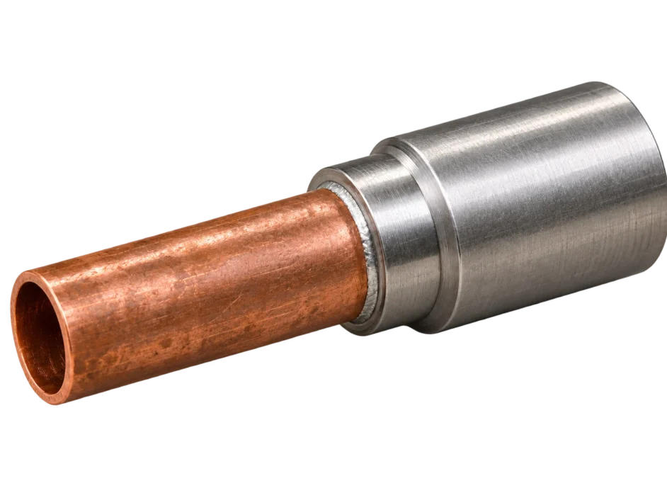
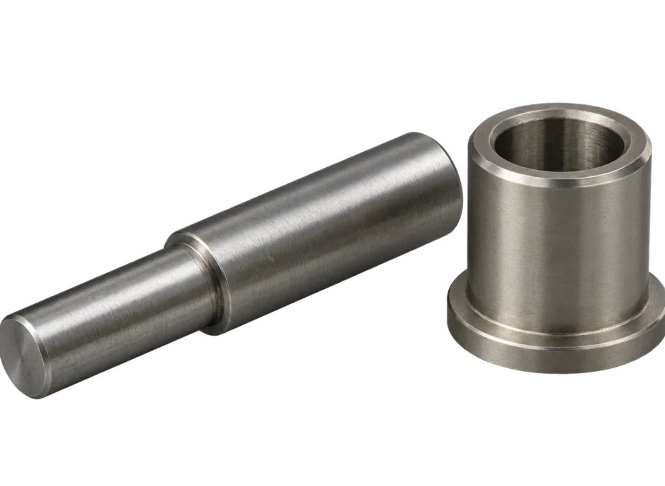
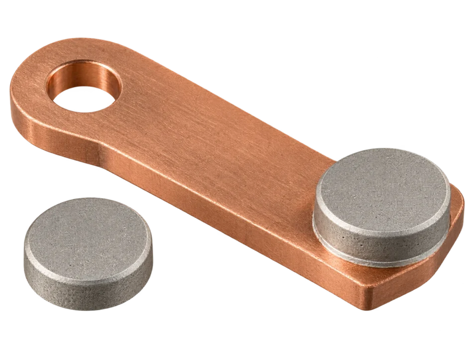
리벳·아일렛·핀·부싱과 관형 연결 부품

PRECISION CONNECTION ENGINEERING

작은 부품으로 잇는
정밀한 구조

리벳·아일렛·핀·슬리브의 기능, 재료와 조립 검증

리벳·아일렛·핀·부싱과 관형 연결 부품

Locate.
Retain.
Support.

PRECISION CONNECTION ENGINEERING

리벳·아일렛·핀·부싱과 관형 연결 부품

맞춤 구조와
끝단 성형

핀·부싱·하우징의 관계와 관형 아일렛이 지지된 상태에서 성형되는 과정을 확인합니다.

하중 · 맞춤 · 성형 · 검증

Overview.

하중을 전달하고 위치와 움직임을 정하는 연결 부품

작은 연결 부품은 조립체의 위치를 정하고 하중을 전달하며 필요한 운동을 허용합니다. 정밀도는 작은 공차의 수치보다 그 공차가 어떤 기능을 유지하는지로 설명되어야 합니다.

리벳과 아일렛의 성형, 핀과 부싱의 맞춤, 샤프트와 관형 부품의 검사까지 재료·공정·조립 조건을 함께 검토하는 방법을 살펴봅니다.

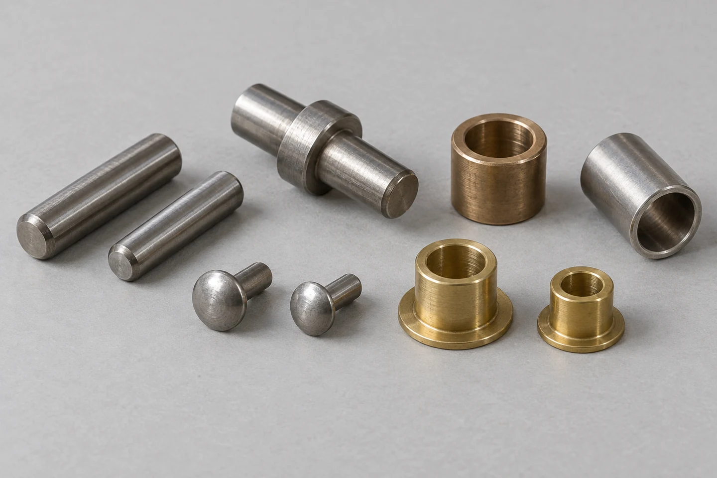
서로 다른 기능을 갖는 정밀 연결 부품의 구성

서로 다른 기능을 갖는 정밀 연결 부품의 구성

Structure.

기능과 하중 경로

01 / 01

연결 부품의 기능을 나누기

고정, 위치 결정, 회전 지지와 간격 유지는 서로 다른 설계 목표입니다.

리벳, 아일렛, 핀, 슬리브, 샤프트와 파이프는 단순한 형상의 금속 부품으로 보이지만 조립체 안에서 수행하는 기능이 다릅니다. 고정할 것인지, 반복 회전을 허용할 것인지, 위치를 정밀하게 결정할 것인지를 먼저 정의해야 합니다.

리벳과 아일렛은 끝단을 성형해 결합을 유지하는 데 사용될 수 있고, 핀은 위치 결정이나 전단 하중 전달을 담당할 수 있습니다. 슬리브와 부싱은 간격 유지 또는 축의 지지면을 제공하며, 샤프트와 관형 부품은 실제 구조에 따라 힘·토크·유체 경로를 형성합니다.

하나의 부품이 여러 기능을 맡으면 요구가 충돌할 수 있습니다. 고정 구간과 회전 구간을 구분하고, 리벳의 기계적 유지가 곧 기밀·수밀을 뜻하지는 않으므로 밀봉 기능이 필요하면 별도 구조와 검증을 정의합니다.

고정·위치 결정

부품의 상대 이동 제한 · 기준면·유지 방식 정의

회전·하중 전달

운동과 지지 하중의 관계 · 회전 구간·지지 구간 구분

간격·관형 경로

조립 간격 또는 내부 통로 · 끝면·보어·연결 조건 명시

연결 부품의 기능을 나누기 — 실무 판단 기준

검토 항목기술적 의미검증·관리 기준
고정·위치 결정부품의 상대 이동 제한기준면·유지 방식 정의
회전·하중 전달운동과 지지 하중의 관계회전 구간·지지 구간 구분
간격·관형 경로조립 간격 또는 내부 통로끝면·보어·연결 조건 명시

고정·위치 결정

기술적 의미
부품의 상대 이동 제한

검증·관리 기준
기준면·유지 방식 정의

회전·하중 전달

기술적 의미
운동과 지지 하중의 관계

검증·관리 기준
회전 구간·지지 구간 구분

간격·관형 경로

기술적 의미
조립 간격 또는 내부 통로

검증·관리 기준
끝면·보어·연결 조건 명시

02 / 02

조립체 전체의 하중 경로

핀의 강도만 계산해서 연결부의 강도를 판단할 수는 없습니다.

연결부에는 전단, 인장, 굽힘과 접촉 압력이 조합되어 작용할 수 있습니다. 힘이 어느 부품에서 들어와 핀이나 리벳, 구멍 벽과 지지 구조를 거쳐 빠져나가는지 먼저 그려 보면 검토해야 할 단면이 드러납니다.

핀 사이의 지지 간격이나 부품 사이의 틈이 커지면 단순 전단뿐 아니라 굽힘의 영향이 증가할 수 있습니다. 구멍 주변의 지압, 가장자리 파손과 얇은 부품의 변형도 핀 자체보다 먼저 한계에 도달할 수 있습니다.

표준 시험 치구에서 얻은 전단 하중은 특정 구속과 간극에서의 결과입니다. 실제 조립체의 재료, 지지 길이와 반복 하중을 반영해 해석하고, 필요한 경우 부품이 조립된 상태로 기능 시험을 실시합니다.

전단·굽힘

지지 간격과 하중 위치의 영향 · 단면과 비지지 구간 검토

구멍 주변

지압·가장자리·국부 변형 · 두께·재료·가장자리 거리 확인

실제 조립

시험 치구와 다른 구속 조건 · 조립 상태의 하중 검증

핀의 강도만 계산해서 연결부의 강도를 판단할 수는 없습니다.

실무 적용

표준 시험 치구에서 얻은 전단 하중은 특정 구속과 간극에서의 결과입니다. 실제 조립체의 재료, 지지 길이와 반복 하중을 반영해 해석하고, 필요한 경우 부품이 조립된 상태로 기능 시험을 실시합니다.

조립체 전체의 하중 경로 — 실무 판단 기준

검토 항목기술적 의미검증·관리 기준
전단·굽힘지지 간격과 하중 위치의 영향단면과 비지지 구간 검토
구멍 주변지압·가장자리·국부 변형두께·재료·가장자리 거리 확인
실제 조립시험 치구와 다른 구속 조건조립 상태의 하중 검증

전단·굽힘

기술적 의미
지지 간격과 하중 위치의 영향

검증·관리 기준
단면과 비지지 구간 검토

구멍 주변

기술적 의미
지압·가장자리·국부 변형

검증·관리 기준
두께·재료·가장자리 거리 확인

실제 조립

기술적 의미
시험 치구와 다른 구속 조건

검증·관리 기준
조립 상태의 하중 검증

Materials.

재료와 기하 기준

03 / 03

강도와 성형성을 함께 보는 재료

높은 경도와 큰 성형 여유는 항상 같은 방향으로 움직이지 않습니다.

재료는 사용 중 하중을 지지하는 능력과 제조 중 변형을 견디는 능력을 함께 고려해 선정합니다. 회전 지지 핀의 내마모 요구와 끝단을 펼쳐야 하는 아일렛의 연성 요구는 다를 수 있습니다.

같은 강종이라도 인발과 냉간 성형, 열처리 이력에 따라 경도와 미세조직이 달라집니다. 특히 관형 리벳의 끝단 성형에서는 소재의 국부 취약부나 앞선 공정의 손상이 균열 발생에 영향을 줄 수 있습니다.

도면에는 재료 이름만 적기보다 필요한 공급 상태, 열처리와 기능에 연결되는 특성을 명시합니다. 강도나 경도를 높이는 변경이 성형성, 상대 부품 마모와 치수 안정성에 주는 영향도 함께 검토합니다.

강도

사용 하중에 대한 저항 · 하중 형태와 허용 기준 연결

연성

성형 중 변형을 수용하는 능력 · 끝단 성형과 균열 검토

재료 이력

인발·열처리·가공 경화 · 공급 상태와 공정 이력 확인

실무 적용

도면에는 재료 이름만 적기보다 필요한 공급 상태, 열처리와 기능에 연결되는 특성을 명시합니다. 강도나 경도를 높이는 변경이 성형성, 상대 부품 마모와 치수 안정성에 주는 영향도 함께 검토합니다.

강도와 성형성을 함께 보는 재료 — 실무 판단 기준

검토 항목기술적 의미검증·관리 기준
강도사용 하중에 대한 저항하중 형태와 허용 기준 연결
연성성형 중 변형을 수용하는 능력끝단 성형과 균열 검토
재료 이력인발·열처리·가공 경화공급 상태와 공정 이력 확인
상대 재료마모·부식·접촉의 조합부품 쌍과 환경으로 평가

강도

기술적 의미
사용 하중에 대한 저항

검증·관리 기준
하중 형태와 허용 기준 연결

연성

기술적 의미
성형 중 변형을 수용하는 능력

검증·관리 기준
끝단 성형과 균열 검토

재료 이력

기술적 의미
인발·열처리·가공 경화

검증·관리 기준
공급 상태와 공정 이력 확인

상대 재료

기술적 의미
마모·부식·접촉의 조합

검증·관리 기준
부품 쌍과 환경으로 평가

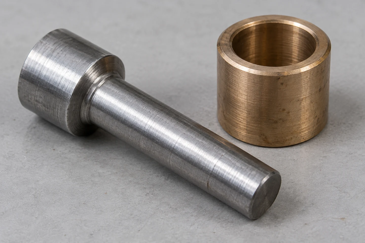
어깨 핀과 부싱의 접촉 및 위치 결정 구조

어깨 핀과 부싱의 접촉 및 위치 결정 구조

04 / 04

끼워맞춤과 기하 기준

지름 공차는 위치와 형상 기준이 맞을 때 기능으로 이어집니다.

끼워맞춤은 단순히 지름을 작게 또는 크게 만드는 문제가 아닙니다. 핀이 한쪽 부품에 고정되고 다른 부품 안에서 회전해야 한다면 각 구간에 요구되는 간극과 유지 방식이 달라집니다.

구멍의 위치, 축의 직선성, 원통도와 기준면에 대한 방향은 조립성과 접촉 분포에 영향을 줍니다. 지름이 합격이어도 두 구멍의 정렬이 맞지 않으면 핀을 억지로 넣어야 하거나 회전 중 한쪽에 하중이 집중될 수 있습니다.

어깨부와 필렛은 축 방향 위치를 정하면서 응력 집중을 완화하는 역할을 할 수 있습니다. 상대 부품의 입구 모따기와 간섭하지 않는지 확인하고, 치수는 도금·열처리 전후 중 어느 상태를 기준으로 하는지 명시합니다.

지름 공차는 위치와 형상 기준이 맞을 때 기능으로 이어집니다.

끼워맞춤과 기하 기준 — 실무 판단 기준

검토 항목기술적 의미검증·관리 기준
끼워맞춤고정·회전·분해 기능의 구분구간별 간극과 유지 방식
기준 체계구멍·축·끝면의 관계기능에 맞는 데이텀 선정
형상·위치정렬과 접촉 분포직선성·원통도·위치 관리
어깨·필렛축 방향 지지와 전이 형상상대 모따기·완성 치수 확인

끼워맞춤

기술적 의미
고정·회전·분해 기능의 구분

검증·관리 기준
구간별 간극과 유지 방식

기준 체계

기술적 의미
구멍·축·끝면의 관계

검증·관리 기준
기능에 맞는 데이텀 선정

형상·위치

기술적 의미
정렬과 접촉 분포

검증·관리 기준
직선성·원통도·위치 관리

어깨·필렛

기술적 의미
축 방향 지지와 전이 형상

검증·관리 기준
상대 모따기·완성 치수 확인

3D · 어깨 핀·부싱·하우징의 결합

STRUCTURE & INTERFACE
ID SOLUTECH / 01
인터랙티브 3D를 준비하고 있습니다.
어깨면 안착

어깨면이 부싱의 끝면에 닿습니다. 반지름 방향 여유와 축 방향 안착은 서로 다릅니다.

드래그·방향키: 회전 / + −: 확대·축소 / Home: 초기화어깨 핀·부싱·하우징의 결합

정밀도는 작은 숫자보다 유지해야 할 기능에서 시작됩니다.

Precision.

제조와 끝단 성형

05 / 05

성형과 절삭 공정의 조합

공정 선택은 형상, 수량과 기능 공차를 함께 고려합니다.

헤딩, 인발과 절삭은 서로 다른 방식으로 소재를 형상화합니다. 성형은 재료의 흐름을 이용해 몸체와 머리를 만들고, 절삭과 연삭은 기능면의 치수와 형상을 조정하는 데 사용할 수 있습니다.

어느 공정이 모든 부품에서 더 강하거나 더 정밀하다고 일반화하기 어렵습니다. 재료 상태, 성형률, 표면 결함, 열처리와 마무리 공정이 최종 특성을 함께 결정하므로 부품의 하중과 공차에 맞는 조합을 선택합니다.

관형 소재의 절단면, 인발 표면과 성형 끝단에는 후속 공정에서 커질 수 있는 결함이 남을 수 있습니다. 중간 단계의 버와 균열, 벽 두께 편차를 관리하고 최종 검사만으로 모든 전공정 문제를 해결하려 하지 않습니다.

헤딩·성형

재료 흐름을 이용한 형상 형성 · 성형률·접힘·균열 검토

인발 소재

관과 선재의 치수·재료 상태 · 벽 두께·표면·공급 이력

절삭·연삭

기능면 치수와 형상 마무리 · 기준·버·표면 손상 확인

실무 적용

관형 소재의 절단면, 인발 표면과 성형 끝단에는 후속 공정에서 커질 수 있는 결함이 남을 수 있습니다. 중간 단계의 버와 균열, 벽 두께 편차를 관리하고 최종 검사만으로 모든 전공정 문제를 해결하려 하지 않습니다.

성형과 절삭 공정의 조합 — 실무 판단 기준

검토 항목기술적 의미검증·관리 기준
헤딩·성형재료 흐름을 이용한 형상 형성성형률·접힘·균열 검토
인발 소재관과 선재의 치수·재료 상태벽 두께·표면·공급 이력
절삭·연삭기능면 치수와 형상 마무리기준·버·표면 손상 확인
공정 연결중간 결함의 후속 확대 가능성단계별 검사와 추적

헤딩·성형

기술적 의미
재료 흐름을 이용한 형상 형성

검증·관리 기준
성형률·접힘·균열 검토

인발 소재

기술적 의미
관과 선재의 치수·재료 상태

검증·관리 기준
벽 두께·표면·공급 이력

절삭·연삭

기술적 의미
기능면 치수와 형상 마무리

검증·관리 기준
기준·버·표면 손상 확인

공정 연결

기술적 의미
중간 결함의 후속 확대 가능성

검증·관리 기준
단계별 검사와 추적

06 / 06

관형 리벳과 아일렛의 끝단 성형

균열 원인은 공구 형상과 소재 이력을 함께 살펴야 찾을 수 있습니다.

관형 끝단을 펼치거나 말아 고정할 때에는 원주 방향의 늘어남과 굽힘이 함께 발생합니다. 성형 시작부의 접촉 형상, 돌출 길이, 벽 두께와 하부 지지는 변형이 어디에 집중되는지를 바꿉니다.

저탄소강 관형 리벳의 파손 분석에서는 공구에 의한 국부 인장 응력뿐 아니라 인발·절단 손상과 미세조직 상태가 함께 문제로 확인되었습니다. 따라서 프레스 하중이나 공구 곡률만 바꾸면 모든 균열이 해결된다고 판단해서는 안 됩니다.

실무에서는 균열 위치와 방향, 성형 전 끝단 상태, 재료 로트와 공정 이력을 연결해 조사합니다. 특정 강종에서 제안된 열처리 조건이나 시험 하중을 황동 아일렛과 스테인리스 슬리브에 그대로 적용하지 않고 각각의 성형 범위를 검증합니다.

돌출 길이

성형에 사용되는 재료량 · 판 두께와 끝단 형상에 맞춤

공구 접촉

초기 변형과 응력 집중 · 곡면·정렬·접촉 순서 검토

소재 상태

연성과 기존 결함의 영향 · 로트·끝단·미세조직 조사

실무 적용

실무에서는 균열 위치와 방향, 성형 전 끝단 상태, 재료 로트와 공정 이력을 연결해 조사합니다. 특정 강종에서 제안된 열처리 조건이나 시험 하중을 황동 아일렛과 스테인리스 슬리브에 그대로 적용하지 않고 각각의 성형 범위를 검증합니다.

관형 리벳과 아일렛의 끝단 성형 — 실무 판단 기준

검토 항목기술적 의미검증·관리 기준
돌출 길이성형에 사용되는 재료량판 두께와 끝단 형상에 맞춤
공구 접촉초기 변형과 응력 집중곡면·정렬·접촉 순서 검토
소재 상태연성과 기존 결함의 영향로트·끝단·미세조직 조사
완성 머리유지 기능과 균열·비대칭형상과 기능 시험 함께 확인

돌출 길이

기술적 의미
성형에 사용되는 재료량

검증·관리 기준
판 두께와 끝단 형상에 맞춤

공구 접촉

기술적 의미
초기 변형과 응력 집중

검증·관리 기준
곡면·정렬·접촉 순서 검토

소재 상태

기술적 의미
연성과 기존 결함의 영향

검증·관리 기준
로트·끝단·미세조직 조사

완성 머리

기술적 의미
유지 기능과 균열·비대칭

검증·관리 기준
형상과 기능 시험 함께 확인

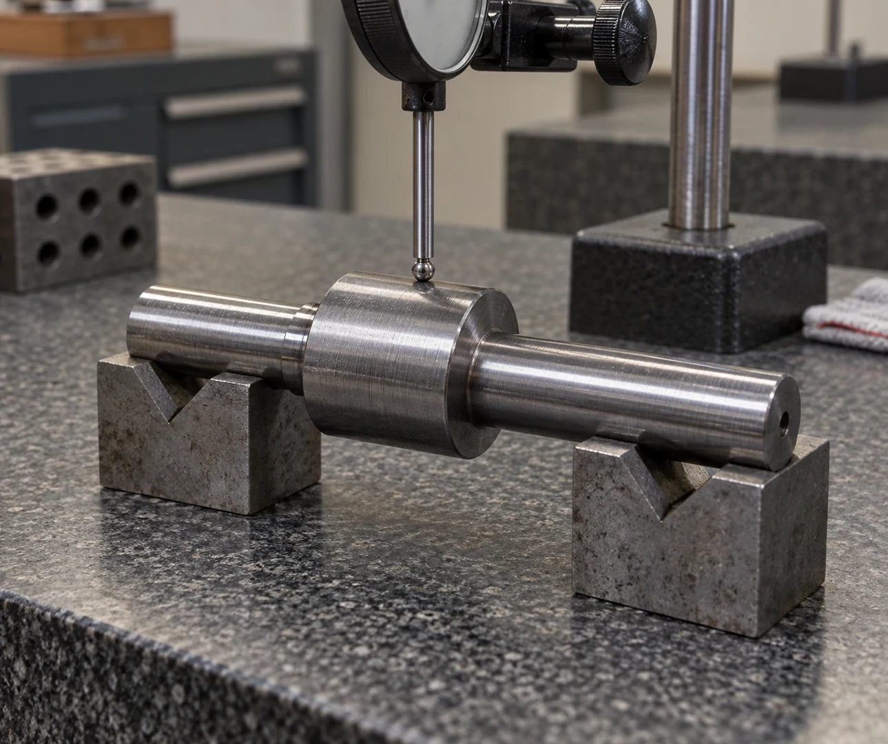
지지된 샤프트의 표면 변위를 확인하는 측정 구성

지지된 샤프트의 표면 변위를 확인하는 측정 구성

Motion.

지지 구조와 기초 계산

07 / 07

핀과 부싱의 지지 구조

회전 가능한 간극과 하중을 받는 접촉 길이를 함께 설계합니다.

핀과 부싱의 조합은 상대 운동을 허용하면서 하중을 지지해야 합니다. 부싱의 설치 후 내경은 하우징 맞춤과 재료에 영향을 받을 수 있으므로 단품 내경만으로 회전 간극을 판단하지 않고 사용 온도와 정렬 조건까지 확인합니다.

부싱의 유효 길이와 지지부 사이의 간격은 접촉 압력과 핀의 굽힘에 영향을 줍니다. 축 방향 스토퍼나 머리는 부품의 이탈을 막는 역할을 하므로 회전 지지면과 별개로 하중과 간섭을 확인합니다.

재료 조합, 표면 거칠기와 윤활은 마찰과 마모에 영향을 주지만 한 조건의 결과를 다른 운동 형태로 일반화하기 어렵습니다. 연속 회전, 짧은 왕복 회전과 진동 중 미소 운동을 구분하고 해당 환경에서 유격과 마모 변화를 확인합니다.

회전 간극

자유 운동과 충격의 균형 · 온도·정렬·공차 조합 검토

지지 길이

접촉 압력과 하중 분산 · 유효 접촉 구간 확인

지지 간격

핀의 굽힘과 기울어짐 · 불필요한 비지지 구간 최소화

회전 가능한 간극과 하중을 받는 접촉 길이를 함께 설계합니다.

실무 적용

완성 조립 상태의 간극과 운동을 확인합니다. 복합 부싱의 특정 공차·윤활 지침을 다른 재료의 슬리브에 그대로 적용하지 않습니다.

핀과 부싱의 지지 구조 — 실무 판단 기준

검토 항목기술적 의미검증·관리 기준
회전 간극자유 운동과 충격의 균형온도·정렬·공차 조합 검토
지지 길이접촉 압력과 하중 분산유효 접촉 구간 확인
지지 간격핀의 굽힘과 기울어짐불필요한 비지지 구간 최소화
축 방향 유지부품 이탈과 끝면 간섭스토퍼·어깨·유격 검증

회전 간극

기술적 의미
자유 운동과 충격의 균형

검증·관리 기준
온도·정렬·공차 조합 검토

지지 길이

기술적 의미
접촉 압력과 하중 분산

검증·관리 기준
유효 접촉 구간 확인

지지 간격

기술적 의미
핀의 굽힘과 기울어짐

검증·관리 기준
불필요한 비지지 구간 최소화

축 방향 유지

기술적 의미
부품 이탈과 끝면 간섭

검증·관리 기준
스토퍼·어깨·유격 검증

3D · 관형 아일렛의 지지와 플레어 성형

PROCESS & VALIDATION
ID SOLUTECH / 02
인터랙티브 3D를 준비하고 있습니다.
플레어 완료

림을 펼쳐 판을 유지합니다. 실제 잔류 체결력이나 균열을 예측하지 않습니다.

드래그·방향키: 회전 / + −: 확대·축소 / Home: 초기화관형 아일렛의 지지와 플레어 성형
08 / 08

전단과 지압의 기초 계산

단순식은 하중 경로를 점검하는 도구이며 전체 설계 판정은 아닙니다.

실핀의 평균 전단 응력은 하중을 전단면의 총 면적으로 나눈 값으로 추정할 수 있습니다. 단전단과 복전단은 전단면 수가 다르지만 복전단이라고 해서 항상 두 면이 동일한 하중을 분담하는 것은 아닙니다.

구멍 벽의 공칭 지압은 해당 부재가 받는 하중을 핀 지름과 부재 두께의 곱으로 나누어 계산합니다. 이는 투영 면적 기준의 평균값이며 실제 곡면 접촉의 최대 압력이나 가장자리 파손을 직접 설명하지는 않습니다.

핀의 굽힘, 구멍 간극, 가장자리 거리, 반복 하중과 재료 허용값을 추가로 검토해야 합니다. 아래 예는 균등 하중 분담을 가정한 실핀의 정적 계산으로 관형 핀이나 성형된 리벳의 강도를 대신하지 않습니다.

τ = F / (nπd²/4); p = F / (dt)

τ: 실핀의 평균 전단 응력[MPa], p: 하중 F를 받는 부재의 공칭 지압[MPa], F: 하중[N], n: 균등 하중을 받는 전단면 수[개], d: 핀 지름[mm], t: 해당 부재 두께[mm]. F=2,000 N, d=5 mm, n=2인 이상적 복전단이면 τ≈50.9 MPa입니다. 전체 하중을 받는 중앙 부재의 t=4 mm이면 p=100 MPa입니다. 외측 두 부재는 각각의 분담 하중으로 계산합니다. 굽힘·간극·피로를 제외한 조건부 예이며 허용 하중의 판정값이 아닙니다.

실무 적용

핀의 굽힘, 구멍 간극, 가장자리 거리, 반복 하중과 재료 허용값을 추가로 검토해야 합니다. 아래 예는 균등 하중 분담을 가정한 실핀의 정적 계산으로 관형 핀이나 성형된 리벳의 강도를 대신하지 않습니다.

전단과 지압의 기초 계산 — 실무 판단 기준

검토 항목기술적 의미검증·관리 기준
전단면 수 n단전단과 복전단의 면적 차이실제 하중 분담 확인
핀 지름 d전단 면적과 투영 면적유효 단면·형상 구분
부재 두께 t구멍 벽 지압의 기준각 부재가 받는 하중 적용
추가 검토굽힘·피로·가장자리 파손조립체 해석과 시험 연결

전단면 수 n

기술적 의미
단전단과 복전단의 면적 차이

검증·관리 기준
실제 하중 분담 확인

핀 지름 d

기술적 의미
전단 면적과 투영 면적

검증·관리 기준
유효 단면·형상 구분

부재 두께 t

기술적 의미
구멍 벽 지압의 기준

검증·관리 기준
각 부재가 받는 하중 적용

추가 검토

기술적 의미
굽힘·피로·가장자리 파손

검증·관리 기준
조립체 해석과 시험 연결

핀의 강도와 조립체의 강도는 같은 질문이 아닙니다.

Interface.

표면과 조립 조건

09 / 09

표면 처리와 완성 치수

표면은 부식과 마모뿐 아니라 끼워맞춤에도 영향을 줍니다.

도금과 코팅은 표면의 환경 반응과 마찰 조건을 바꾸고 완성 치수에도 영향을 줍니다. 축과 구멍의 공차가 작다면 처리 전 치수와 처리 후 검사 기준을 분리해 명확하게 관리해야 합니다.

표면 경도만으로 마모 수명을 판단하기 어렵습니다. 상대 재료, 접촉 압력, 거칠기와 윤활 조건을 함께 검토하며, 회전부의 표면 손상이나 응착은 조립 간극과 사용 환경의 문제일 수도 있습니다.

고강도 강재의 일부 전기 도금 공정에서는 수소에 의한 취성 위험을 검토해야 합니다. 이 위험을 모든 금속 부품에 동일하게 적용하거나 특정 후처리가 항상 해결한다고 가정하지 말고 재료·공정·적용 요구에 맞는 관리를 정합니다.

표면은 부식과 마모뿐 아니라 끼워맞춤에도 영향을 줍니다.

실무 적용

고강도 강재의 일부 전기 도금 공정에서는 수소에 의한 취성 위험을 검토해야 합니다. 이 위험을 모든 금속 부품에 동일하게 적용하거나 특정 후처리가 항상 해결한다고 가정하지 말고 재료·공정·적용 요구에 맞는 관리를 정합니다.

표면 처리와 완성 치수 — 실무 판단 기준

검토 항목기술적 의미검증·관리 기준
처리 두께축·구멍의 완성 치수 변화도면의 검사 상태 명시
접촉 표면마찰·응착·마모의 조건상대 재료와 거칠기 검토
환경 적합성부식과 이종 재료 영향실제 노출과 조합 평가
고강도 강재공정별 취성 위험 가능성재료·도금 공정 요구 확인

처리 두께

기술적 의미
축·구멍의 완성 치수 변화

검증·관리 기준
도면의 검사 상태 명시

접촉 표면

기술적 의미
마찰·응착·마모의 조건

검증·관리 기준
상대 재료와 거칠기 검토

환경 적합성

기술적 의미
부식과 이종 재료 영향

검증·관리 기준
실제 노출과 조합 평가

고강도 강재

기술적 의미
공정별 취성 위험 가능성

검증·관리 기준
재료·도금 공정 요구 확인

10 / 10

조립 하중과 지지 치구

삽입과 성형에 필요한 힘이 얇은 부품을 통해 잘못 전달되지 않아야 합니다.

압입, 핀 삽입과 리벳 성형은 각각 적절한 지지가 필요합니다. 힘을 받는 부위 가까이에서 지지하지 않으면 얇은 판이 휘거나 하우징이 변형되어 조립 후 정렬과 간극이 달라질 수 있습니다.

공구는 의도한 어깨나 성형면에 하중을 전달해야 합니다. 관형 부품의 보어를 통과하는 파일럿은 정렬을 돕도록 여유를 두고, 공구가 내부 통로를 막거나 상대 부품을 불필요하게 누르는지 확인합니다.

조립 힘과 변위의 기록은 부품 누락, 잘못된 삽입이나 마찰 변화의 단서를 줄 수 있습니다. 그러나 유사한 곡선이 동일한 품질을 보장하지 않으므로 완성 높이, 좌면 밀착, 회전 기능과 필요한 유지 시험을 함께 사용합니다.

하부 지지

판과 하우징의 변형 억제 · 하중 근처의 지지면 확보

공구 접촉면

힘이 전달되는 위치 · 어깨·성형면과 정렬 확인

파일럿·보어

정렬과 내부 통로의 유지 · 간극·간섭·막힘 확인

실무 적용

조립 힘과 변위의 기록은 부품 누락, 잘못된 삽입이나 마찰 변화의 단서를 줄 수 있습니다. 그러나 유사한 곡선이 동일한 품질을 보장하지 않으므로 완성 높이, 좌면 밀착, 회전 기능과 필요한 유지 시험을 함께 사용합니다.

조립 하중과 지지 치구 — 실무 판단 기준

검토 항목기술적 의미검증·관리 기준
하부 지지판과 하우징의 변형 억제하중 근처의 지지면 확보
공구 접촉면힘이 전달되는 위치어깨·성형면과 정렬 확인
파일럿·보어정렬과 내부 통로의 유지간극·간섭·막힘 확인
조립 판정하중 기록과 완성 기능높이·밀착·회전·유지 시험

하부 지지

기술적 의미
판과 하우징의 변형 억제

검증·관리 기준
하중 근처의 지지면 확보

공구 접촉면

기술적 의미
힘이 전달되는 위치

검증·관리 기준
어깨·성형면과 정렬 확인

파일럿·보어

기술적 의미
정렬과 내부 통로의 유지

검증·관리 기준
간극·간섭·막힘 확인

조립 판정

기술적 의미
하중 기록과 완성 기능

검증·관리 기준
높이·밀착·회전·유지 시험

Validation.

검사와 생산 관리

11 / 11

치수 검사와 기능 시험

측정 기준이 사용 중 기능과 연결될 때 검사 결과의 의미가 분명해집니다.

핀과 샤프트의 지름, 직선성, 원통도와 런아웃은 서로 다른 특성을 나타냅니다. 단일 측정값으로 모두를 대신하지 말고 도면의 기준축과 측정 구속 조건을 명확히 해 필요한 특성을 평가합니다.

리벳과 아일렛은 성형 머리의 높이·외경·대칭과 균열, 조립품의 유지 상태를 확인합니다. 외관이 양호해도 유효 결합이 부족할 수 있으므로 용도에 따라 인장·전단·회전 또는 반복 하중 시험을 구성합니다.

시험 시편 수와 장착 상태, 하중 방향과 파손 기준을 기록해야 결과를 비교할 수 있습니다. 가속 시험은 실제 고장 모드를 유지하는 범위에서 설계하고, 다른 파손 기구를 만들어낸 빠른 시험을 그대로 사용 수명으로 환산하지 않습니다.

치수·형상

크기와 축·면의 기하 관계 · 기준과 측정 구속 명시

성형 외관

머리 형상과 국부 결함 · 높이·대칭·균열 관찰

기능 시험

하중 전달과 운동 유지 · 용도별 방향·하중·판정

측정 기준이 사용 중 기능과 연결될 때 검사 결과의 의미가 분명해집니다.

실무 적용

시험 시편 수와 장착 상태, 하중 방향과 파손 기준을 기록해야 결과를 비교할 수 있습니다. 가속 시험은 실제 고장 모드를 유지하는 범위에서 설계하고, 다른 파손 기구를 만들어낸 빠른 시험을 그대로 사용 수명으로 환산하지 않습니다.

치수 검사와 기능 시험 — 실무 판단 기준

검토 항목기술적 의미검증·관리 기준
치수·형상크기와 축·면의 기하 관계기준과 측정 구속 명시
성형 외관머리 형상과 국부 결함높이·대칭·균열 관찰
기능 시험하중 전달과 운동 유지용도별 방향·하중·판정
반복 시험시간에 따른 손상 축적사용 모드·장착·표본 기록

치수·형상

기술적 의미
크기와 축·면의 기하 관계

검증·관리 기준
기준과 측정 구속 명시

성형 외관

기술적 의미
머리 형상과 국부 결함

검증·관리 기준
높이·대칭·균열 관찰

기능 시험

기술적 의미
하중 전달과 운동 유지

검증·관리 기준
용도별 방향·하중·판정

반복 시험

기술적 의미
시간에 따른 손상 축적

검증·관리 기준
사용 모드·장착·표본 기록

12 / 12

도면 협의와 생산 추적

부품의 형상과 사용 기능을 함께 전달하면 검토의 정확도가 높아집니다.

제작 검토에는 단품 도면과 함께 상대 부품의 구멍, 판 두께, 기준면과 조립 순서를 제시하는 것이 좋습니다. 고정, 회전, 간격 유지 중 어느 기능이 중요한지에 따라 공차와 검사 방법의 우선순위가 달라집니다.

재료 로트, 성형·가공·열처리·표면 처리 이력과 최종 검사 결과를 연결해 추적합니다. 특히 성형 균열이나 간헐적인 조립 불량은 최종 치수만으로 원인을 찾기 어려워 전공정 이력이 중요한 단서가 됩니다.

대체 소재나 공정 변경은 영향 특성을 기준으로 검토합니다. 필요한 유지력, 회전 간극, 외관 한계와 시험 범위를 사전에 합의하면 불필요한 과도 공차를 줄이면서 기능에 직접 연결되는 항목에 관리 역량을 집중할 수 있습니다.

기능 정보

고정·운동·하중의 우선순위 · 단품과 상대 부품 도면 공유

공정 이력

상태 변화와 결함 발생 경로 · 로트·열처리·표면 처리 연결

검사 계획

기능을 판단하는 근거 · 기준·방법·표본·합격값 합의

실무 적용

대체 소재나 공정 변경은 영향 특성을 기준으로 검토합니다. 필요한 유지력, 회전 간극, 외관 한계와 시험 범위를 사전에 합의하면 불필요한 과도 공차를 줄이면서 기능에 직접 연결되는 항목에 관리 역량을 집중할 수 있습니다.

도면 협의와 생산 추적 — 실무 판단 기준

검토 항목기술적 의미검증·관리 기준
기능 정보고정·운동·하중의 우선순위단품과 상대 부품 도면 공유
공정 이력상태 변화와 결함 발생 경로로트·열처리·표면 처리 연결
검사 계획기능을 판단하는 근거기준·방법·표본·합격값 합의
변경 관리재료와 공정 대체의 영향필요 특성의 재검증 기록

기능 정보

기술적 의미
고정·운동·하중의 우선순위

검증·관리 기준
단품과 상대 부품 도면 공유

공정 이력

기술적 의미
상태 변화와 결함 발생 경로

검증·관리 기준
로트·열처리·표면 처리 연결

검사 계획

기술적 의미
기능을 판단하는 근거

검증·관리 기준
기준·방법·표본·합격값 합의

변경 관리

기술적 의미
재료와 공정 대체의 영향

검증·관리 기준
필요 특성의 재검증 기록

성형 균열을 이해하려면 공구와 소재가 지나온 과정을 함께 살펴야 합니다.

Start a
Project.

단품·상대 부품 도면, 재료, 하중과 조립·운동 조건을 함께 전달해 주세요.

Share component and mating-part drawings, material, loading, assembly and motion requirements.

개발 상담 · Contact

기술 협의 · Engineering Consultation
도면과 사양을 기준으로 소재·가공·표면처리,
주요 품질 항목과 공급 조건을 함께 검토합니다.


We review drawings and specifications to define materials, manufacturing methods, surface finishes, key quality requirements, and supply conditions.

개발 의뢰하기 · Development Inquiry

    도면 및 기술자료
    Drawings & Technical Documents

    도면 번호와 개정 이력이 표시된 2D·3D 도면을 첨부해 주세요.
    사양서와 검사 기준도 함께 전달할 수 있습니다.
    Attach your 2D or 3D drawings with their drawing numbers and revisions.
    Include specifications and inspection criteria as needed.

    파일을 이곳에 놓아주세요Drag & drop your files here

    선택된 파일 없음 / No files attached

    최대 5개 · 파일당 5MB · 총 15MB / Up to 5 files · 5MB each · 15MB total
    PDF · DWG · DXF · STEP/STP · IGS/IGES · JPG · PNG · ZIP

    * 필수 입력 / Required fields

    PRECISION CONNECTION ENGINEERING

    리벳·아일렛·핀·부싱과 관형 연결 부품

    Fit geometry
    and end forming

    Explore a pin, bushing and housing interface, then follow supported tubular-eyelet forming.

    Load · Fit · Forming · Validation

    ENGLISH EDITION

    Precision structures
    through small components

    Function, materials and assembly validation for rivets, eyelets, pins and sleeves

    Components that transfer load and establish position and motion

    Small connection components establish position, transfer load and permit intended motion. Precision is best described by the function a tolerance preserves, rather than by a small number alone.

    Explore a combined review of materials, processes and assembly conditions, from rivet and eyelet forming to pin–bushing fits and shaft and tube inspection.

    서로 다른 기능을 갖는 정밀 연결 부품의 구성

    Precision connection components serving different functions

    Structure.

    Function and load paths

    01 / 01

    Define the function of the connection

    Retention, location, rotational support and spacing are different design objectives.

    Rivets, eyelets, pins, sleeves, shafts and tubes may look like simple metal parts, but their assembly functions differ. First define whether the connection must retain parts, permit repeated rotation or establish precise location.

    Rivets and eyelets can retain a joint through end forming, while pins can locate parts or transfer shear. Sleeves and bushings provide spacing or shaft support; shafts and tubular parts carry force, torque or fluid according to their actual construction.

    Combining functions can create competing requirements. Separate fixed and rotating regions, and remember that mechanical retention by a rivet does not inherently establish air or liquid sealing; define a separate sealing arrangement and validation when needed.

    Retention and location

    Restraining relative movement. Define datums and retention method

    Rotation and load transfer

    Relationship of motion to support load. Separate moving and supported regions

    Spacing and tubular paths

    Assembly spacing or an internal passage. Specify faces, bores and connection conditions

    Define the function of the connection — Review Criteria

    Review itemEngineering significanceVerification or control
    Retention and locationRestraining relative movementDefine datums and retention method
    Rotation and load transferRelationship of motion to support loadSeparate moving and supported regions
    Spacing and tubular pathsAssembly spacing or an internal passageSpecify faces, bores and connection conditions

    Retention and location

    Engineering significance
    Restraining relative movement

    Verification or control
    Define datums and retention method

    Rotation and load transfer

    Engineering significance
    Relationship of motion to support load

    Verification or control
    Separate moving and supported regions

    Spacing and tubular paths

    Engineering significance
    Assembly spacing or an internal passage

    Verification or control
    Specify faces, bores and connection conditions

    02 / 02

    The load path through the assembly

    Pin strength alone does not establish the strength of the complete joint.

    A connection can experience combined shear, tension, bending and contact pressure. Trace force from the loaded part through the pin or rivet, hole wall and supporting structure to identify the sections that require review.

    A larger unsupported span or gap between components can increase bending in addition to shear. Hole bearing, edge failure and deformation of thin members may become limiting before the pin itself fails.

    A shear load measured in a standard fixture applies to its particular restraint and clearance. Interpret it using the actual assembly materials, support lengths and cyclic loads, and perform assembled functional testing where required.

    Shear and bending

    Effects of support span and load location. Review sections and unsupported regions

    Hole region

    Bearing, edge failure and local deformation. Check thickness, material and edge distance

    Actual assembly

    Restraint differs from a test fixture. Verify loading in the assembled state

    Pin strength alone does not establish the strength of the complete joint.

    Application review

    A shear load measured in a standard fixture applies to its particular restraint and clearance. Interpret it using the actual assembly materials, support lengths and cyclic loads, and perform assembled functional testing where required.

    The load path through the assembly — Review Criteria

    Review itemEngineering significanceVerification or control
    Shear and bendingEffects of support span and load locationReview sections and unsupported regions
    Hole regionBearing, edge failure and local deformationCheck thickness, material and edge distance
    Actual assemblyRestraint differs from a test fixtureVerify loading in the assembled state

    Shear and bending

    Engineering significance
    Effects of support span and load location

    Verification or control
    Review sections and unsupported regions

    Hole region

    Engineering significance
    Bearing, edge failure and local deformation

    Verification or control
    Check thickness, material and edge distance

    Actual assembly

    Engineering significance
    Restraint differs from a test fixture

    Verification or control
    Verify loading in the assembled state

    Materials.

    Materials and geometric references

    03 / 03

    Materials for strength and formability

    High hardness and large forming capacity do not always develop together.

    Select material for both load support in service and deformation during manufacture. A rotating support pin’s wear requirements can differ from the ductility needed to flare an eyelet end.

    Drawing, cold forming and heat-treatment history can change hardness and microstructure within the same steel grade. In tubular-rivet end forming, local material weakness or damage from earlier operations can influence cracking.

    Specify supply condition, heat treatment and functionally relevant properties rather than material name alone. Review how increases in strength or hardness affect formability, counterface wear and dimensional stability.

    Strength

    Resistance to service loading. Relate loading to acceptance criteria

    Ductility

    Capacity to accommodate forming strain. Review end forming and cracks

    Material history

    Drawing, heat treatment and work hardening. Verify supply condition and process history

    Application review

    Specify supply condition, heat treatment and functionally relevant properties rather than material name alone. Review how increases in strength or hardness affect formability, counterface wear and dimensional stability.

    Materials for strength and formability — Review Criteria

    Review itemEngineering significanceVerification or control
    StrengthResistance to service loadingRelate loading to acceptance criteria
    DuctilityCapacity to accommodate forming strainReview end forming and cracks
    Material historyDrawing, heat treatment and work hardeningVerify supply condition and process history
    Material pairCombined wear, corrosion and contact behaviorAssess both parts and the environment

    Strength

    Engineering significance
    Resistance to service loading

    Verification or control
    Relate loading to acceptance criteria

    Ductility

    Engineering significance
    Capacity to accommodate forming strain

    Verification or control
    Review end forming and cracks

    Material history

    Engineering significance
    Drawing, heat treatment and work hardening

    Verification or control
    Verify supply condition and process history

    Material pair

    Engineering significance
    Combined wear, corrosion and contact behavior

    Verification or control
    Assess both parts and the environment

    어깨 핀과 부싱의 접촉 및 위치 결정 구조

    Contact and location features of a shoulder pin and bushing

    04 / 04

    Fits and geometric references

    Diameter tolerances serve function only with coherent location and form requirements.

    A fit is more than making a diameter slightly larger or smaller. If a pin must remain fixed in one member while rotating in another, each region needs its own clearance and retention requirement.

    Hole position, shaft straightness, cylindricity and orientation to datums affect assembly and contact distribution. Acceptable diameters do not prevent forced assembly or one-sided loading when two holes are misaligned.

    A shoulder and fillet can establish axial position while moderating stress concentration. Check clearance to the mating entry chamfer and specify whether dimensions apply before or after coating and heat treatment.

    Diameter tolerances serve function only with coherent location and form requirements.

    Fits and geometric references — Review Criteria

    Review itemEngineering significanceVerification or control
    FitDistinguishing retention, rotation and removalSpecify clearance and retention by region
    Datum systemRelationship of bores, axes and facesSelect function-based references
    Form and positionAlignment and contact distributionControl straightness, cylindricity and position
    Shoulder and filletAxial support and transition geometryCheck mating chamfers and finished dimensions

    Fit

    Engineering significance
    Distinguishing retention, rotation and removal

    Verification or control
    Specify clearance and retention by region

    Datum system

    Engineering significance
    Relationship of bores, axes and faces

    Verification or control
    Select function-based references

    Form and position

    Engineering significance
    Alignment and contact distribution

    Verification or control
    Control straightness, cylindricity and position

    Shoulder and fillet

    Engineering significance
    Axial support and transition geometry

    Verification or control
    Check mating chamfers and finished dimensions

    3D · Shouldered Pin, Bushing and Housing

    STRUCTURE & INTERFACE
    ID SOLUTECH / 01
    Preparing interactive 3D.
    Seat shoulder

    The shoulder touches the bushing end. Radial clearance differs from axial seating.

    Drag / arrow keys: rotate · + −: zoom · Home: resetShouldered Pin, Bushing and Housing

    Precision begins with the function that must be preserved.

    Precision.

    Manufacturing and end forming

    05 / 05

    Combining forming and machining

    Process selection combines geometry, volume and functional tolerances.

    Heading, drawing and machining shape material by different mechanisms. Forming uses material flow to create bodies and heads, while cutting and grinding can establish dimensions and form on functional surfaces.

    No process is universally stronger or more precise for every part. Material condition, forming strain, surface defects, heat treatment and finishing act together, so select a process combination for the loads and tolerances of the component.

    Cut tube ends, drawn surfaces and formed edges can contain defects that grow during later operations. Control intermediate burrs, cracks and wall-thickness variation rather than relying on final inspection to resolve all upstream problems.

    Heading and forming

    Shape generation through material flow. Review strain, laps and cracks

    Drawn stock

    Dimensions and condition of tube and wire. Check wall, surface and supply history

    Machining and grinding

    Finishing functional dimensions and form. Check datums, burrs and surface damage

    Application review

    Cut tube ends, drawn surfaces and formed edges can contain defects that grow during later operations. Control intermediate burrs, cracks and wall-thickness variation rather than relying on final inspection to resolve all upstream problems.

    Combining forming and machining — Review Criteria

    Review itemEngineering significanceVerification or control
    Heading and formingShape generation through material flowReview strain, laps and cracks
    Drawn stockDimensions and condition of tube and wireCheck wall, surface and supply history
    Machining and grindingFinishing functional dimensions and formCheck datums, burrs and surface damage
    Process sequencePossible growth of intermediate defectsUse stage-specific inspection and traceability

    Heading and forming

    Engineering significance
    Shape generation through material flow

    Verification or control
    Review strain, laps and cracks

    Drawn stock

    Engineering significance
    Dimensions and condition of tube and wire

    Verification or control
    Check wall, surface and supply history

    Machining and grinding

    Engineering significance
    Finishing functional dimensions and form

    Verification or control
    Check datums, burrs and surface damage

    Process sequence

    Engineering significance
    Possible growth of intermediate defects

    Verification or control
    Use stage-specific inspection and traceability

    06 / 06

    End forming of tubular rivets and eyelets

    Investigate tool geometry and material history together when a formed rim cracks.

    Flaring or rolling a tubular end combines circumferential stretching with bending. Initial tool contact, protrusion, wall thickness and lower support change where deformation concentrates.

    A failure investigation of low-carbon-steel tubular rivets identified contributions from local tool-driven tensile stress, drawing and cutting damage, and microstructural condition. Changing press force or tool curvature alone therefore cannot be assumed to eliminate every rim crack.

    Relate crack location and direction to the unformed edge, material lot and process history. Validate each material’s forming window rather than transferring a heat-treatment recipe or test load from one steel to brass eyelets or stainless sleeves.

    Protrusion

    Material available for forming. Match stack thickness and final rim

    Tool contact

    Initial deformation and stress concentration. Review curvature, alignment and sequence

    Material condition

    Ductility and pre-existing damage. Investigate lots, edges and microstructure

    Application review

    Relate crack location and direction to the unformed edge, material lot and process history. Validate each material’s forming window rather than transferring a heat-treatment recipe or test load from one steel to brass eyelets or stainless sleeves.

    End forming of tubular rivets and eyelets — Review Criteria

    Review itemEngineering significanceVerification or control
    ProtrusionMaterial available for formingMatch stack thickness and final rim
    Tool contactInitial deformation and stress concentrationReview curvature, alignment and sequence
    Material conditionDuctility and pre-existing damageInvestigate lots, edges and microstructure
    Formed headRetention, cracks and asymmetryAssess geometry with functional tests

    Protrusion

    Engineering significance
    Material available for forming

    Verification or control
    Match stack thickness and final rim

    Tool contact

    Engineering significance
    Initial deformation and stress concentration

    Verification or control
    Review curvature, alignment and sequence

    Material condition

    Engineering significance
    Ductility and pre-existing damage

    Verification or control
    Investigate lots, edges and microstructure

    Formed head

    Engineering significance
    Retention, cracks and asymmetry

    Verification or control
    Assess geometry with functional tests

    지지된 샤프트의 표면 변위를 확인하는 측정 구성

    Measuring surface displacement on a supported shaft

    Motion.

    Support geometry and first estimates

    07 / 07

    Support geometry for pins and bushings

    Design rotational clearance together with the length that supports load.

    A pin and bushing must permit relative motion while supporting load. Housing fit and material can affect the bushing bore after installation, so assess operating clearance in the mounted condition, including service temperature and alignment, rather than from the loose bushing bore alone.

    Effective bushing length and spacing between supports influence contact pressure and pin bending. An axial stop or head prevents escape, so assess its load and clearance separately from the rotating bearing surface.

    Material pairing, surface finish and lubrication affect friction and wear, but a result for one motion regime is not universal. Distinguish continuous rotation, short oscillation and vibration-induced micromotion, and verify clearance and wear in the relevant environment.

    Rotational clearance

    Balance free motion and impact. Review temperature, alignment and tolerances

    Support length

    Contact pressure and load distribution. Check the effective contact region

    Support spacing

    Pin bending and angular displacement. Limit unnecessary unsupported span

    Design rotational clearance together with the length that supports load.

    Application review

    Check clearance and motion in the finished assembly; do not transfer a composite-bushing tolerance or lubrication prescription directly to another sleeve material.

    Support geometry for pins and bushings — Review Criteria

    Review itemEngineering significanceVerification or control
    Rotational clearanceBalance free motion and impactReview temperature, alignment and tolerances
    Support lengthContact pressure and load distributionCheck the effective contact region
    Support spacingPin bending and angular displacementLimit unnecessary unsupported span
    Axial retentionEscape prevention and end-face clearanceVerify stops, shoulders and axial play

    Rotational clearance

    Engineering significance
    Balance free motion and impact

    Verification or control
    Review temperature, alignment and tolerances

    Support length

    Engineering significance
    Contact pressure and load distribution

    Verification or control
    Check the effective contact region

    Support spacing

    Engineering significance
    Pin bending and angular displacement

    Verification or control
    Limit unnecessary unsupported span

    Axial retention

    Engineering significance
    Escape prevention and end-face clearance

    Verification or control
    Verify stops, shoulders and axial play

    3D · Supporting and Flaring a Tubular Eyelet

    PROCESS & VALIDATION
    ID SOLUTECH / 02
    Preparing interactive 3D.
    Complete flare

    Flare the rim to retain the plates. Residual clamp load and cracking are not predicted.

    Drag / arrow keys: rotate · + −: zoom · Home: resetSupporting and Flaring a Tubular Eyelet
    08 / 08

    First estimates of shear and bearing

    Simple equations help check a load path but do not approve a complete design.

    Average shear stress in a solid pin can be estimated by dividing load by total shear-plane area. Single and double shear have different plane counts, but two planes do not always share load equally.

    Nominal hole-bearing stress divides the load carried by a member by pin diameter multiplied by member thickness. This projected-area average does not directly describe maximum curved-surface contact pressure or edge failure.

    Also review pin bending, hole clearance, edge distance, cyclic loading and material allowables. The example below is a static solid-pin estimate with equal load sharing, not a strength rating for tubular pins or formed rivets.

    τ = F / (nπd²/4); p = F / (dt)

    τ: average solid-pin shear stress [MPa]; p: nominal bearing stress in a member carrying F [MPa]; F: load [N]; n: equally loaded shear planes; d: pin diameter [mm]; t: thickness of that member [mm]. For ideal double shear with F=2,000 N, d=5 mm and n=2, τ≈50.9 MPa. A central member carrying the full load with t=4 mm has p=100 MPa. Calculate each outer member using its own share of load. This conditional example excludes bending, clearance and fatigue and is not an allowable-load decision.

    Application review

    Also review pin bending, hole clearance, edge distance, cyclic loading and material allowables. The example below is a static solid-pin estimate with equal load sharing, not a strength rating for tubular pins or formed rivets.

    First estimates of shear and bearing — Review Criteria

    Review itemEngineering significanceVerification or control
    Plane count nArea difference between single and double shearCheck actual load sharing
    Pin diameter dShear and projected bearing areaDistinguish effective section and geometry
    Member thickness tThe basis of hole-bearing areaUse the load carried by each member
    Additional checksBending, fatigue and edge failureConnect assembly analysis and testing

    Plane count n

    Engineering significance
    Area difference between single and double shear

    Verification or control
    Check actual load sharing

    Pin diameter d

    Engineering significance
    Shear and projected bearing area

    Verification or control
    Distinguish effective section and geometry

    Member thickness t

    Engineering significance
    The basis of hole-bearing area

    Verification or control
    Use the load carried by each member

    Additional checks

    Engineering significance
    Bending, fatigue and edge failure

    Verification or control
    Connect assembly analysis and testing

    Pin strength and assembly strength are different engineering questions.

    Interface.

    Surfaces and assembly conditions

    09 / 09

    Surface treatments and finished dimensions

    Surface condition affects fit as well as corrosion and wear.

    Plating and coatings change environmental response, friction and finished dimensions. Tight shaft and bore tolerances require clear control of pre-treatment dimensions and post-treatment inspection criteria.

    Surface hardness alone does not predict wear life. Review counterface material, pressure, roughness and lubrication together; damage or adhesion at a rotating interface may also reflect clearance or service conditions.

    Some electroplating processes on high-strength steel require review of hydrogen-related embrittlement risk. Do not assign the same risk to every metal or assume one post-treatment always resolves it; specify controls for the material, process and application.

    Surface condition affects fit as well as corrosion and wear.

    Application review

    Some electroplating processes on high-strength steel require review of hydrogen-related embrittlement risk. Do not assign the same risk to every metal or assume one post-treatment always resolves it; specify controls for the material, process and application.

    Surface treatments and finished dimensions — Review Criteria

    Review itemEngineering significanceVerification or control
    Treatment thicknessChanges to finished shaft and bore sizeState the drawing inspection condition
    Contact surfaceConditions for friction, adhesion and wearReview counterface and roughness
    EnvironmentCorrosion and dissimilar-material effectsAssess actual exposure and pairing
    High-strength steelPotential process-specific embrittlementCheck material and plating requirements

    Treatment thickness

    Engineering significance
    Changes to finished shaft and bore size

    Verification or control
    State the drawing inspection condition

    Contact surface

    Engineering significance
    Conditions for friction, adhesion and wear

    Verification or control
    Review counterface and roughness

    Environment

    Engineering significance
    Corrosion and dissimilar-material effects

    Verification or control
    Assess actual exposure and pairing

    High-strength steel

    Engineering significance
    Potential process-specific embrittlement

    Verification or control
    Check material and plating requirements

    10 / 10

    Assembly force and supporting fixtures

    Insertion and forming loads need a controlled path through the assembly.

    Press fits, pin insertion and rivet forming each require suitable support. Without support near the loaded region, a thin plate can bend or a housing can deform, changing final alignment and clearance.

    The tool must transmit load through the intended shoulder or forming surface. A pilot passing through a tubular bore needs alignment clearance; check that tooling does not obstruct the passage or unnecessarily load a mating component.

    Force–displacement records can indicate missing parts, incorrect insertion or friction changes. Similar curves do not guarantee identical quality, so also assess final height, seating, rotational function and the required retention tests.

    Lower support

    Limiting plate and housing deformation. Support close to the loaded region

    Tool contact

    Where force enters the part. Align shoulders and forming surfaces

    Pilot and bore

    Alignment and passage preservation. Check clearance, interference and obstruction

    Application review

    Force–displacement records can indicate missing parts, incorrect insertion or friction changes. Similar curves do not guarantee identical quality, so also assess final height, seating, rotational function and the required retention tests.

    Assembly force and supporting fixtures — Review Criteria

    Review itemEngineering significanceVerification or control
    Lower supportLimiting plate and housing deformationSupport close to the loaded region
    Tool contactWhere force enters the partAlign shoulders and forming surfaces
    Pilot and boreAlignment and passage preservationCheck clearance, interference and obstruction
    Assembly acceptanceProcess records and finished functionCheck height, seating, rotation and retention

    Lower support

    Engineering significance
    Limiting plate and housing deformation

    Verification or control
    Support close to the loaded region

    Tool contact

    Engineering significance
    Where force enters the part

    Verification or control
    Align shoulders and forming surfaces

    Pilot and bore

    Engineering significance
    Alignment and passage preservation

    Verification or control
    Check clearance, interference and obstruction

    Assembly acceptance

    Engineering significance
    Process records and finished function

    Verification or control
    Check height, seating, rotation and retention

    Validation.

    Inspection and production control

    11 / 11

    Dimensional and functional verification

    Inspection is most useful when its references reflect the service function.

    Diameter, straightness, cylindricity and runout describe different shaft and pin characteristics. Do not replace all of them with one reading; define the drawing axis and measurement restraint for the property being assessed.

    For rivets and eyelets, inspect formed-head height, diameter, symmetry, cracks and assembly retention. Good appearance can coexist with insufficient engagement, so choose tensile, shear, rotational or cyclic testing according to function.

    Comparisons require recorded sample count, mounting, load direction and failure criteria. Design accelerated tests to preserve the relevant failure mechanism; a faster test that introduces another mechanism cannot simply be converted into service life.

    Dimensions and form

    Size and geometric relationships. Specify datums and measurement restraint

    Formed appearance

    Head geometry and local defects. Inspect height, symmetry and cracks

    Functional test

    Load transfer and retained motion. Define service-specific direction, load and acceptance

    Inspection is most useful when its references reflect the service function.

    Application review

    Comparisons require recorded sample count, mounting, load direction and failure criteria. Design accelerated tests to preserve the relevant failure mechanism; a faster test that introduces another mechanism cannot simply be converted into service life.

    Dimensional and functional verification — Review Criteria

    Review itemEngineering significanceVerification or control
    Dimensions and formSize and geometric relationshipsSpecify datums and measurement restraint
    Formed appearanceHead geometry and local defectsInspect height, symmetry and cracks
    Functional testLoad transfer and retained motionDefine service-specific direction, load and acceptance
    Cyclic testingDamage accumulation with repetitionRecord service mode, mounting and specimens

    Dimensions and form

    Engineering significance
    Size and geometric relationships

    Verification or control
    Specify datums and measurement restraint

    Formed appearance

    Engineering significance
    Head geometry and local defects

    Verification or control
    Inspect height, symmetry and cracks

    Functional test

    Engineering significance
    Load transfer and retained motion

    Verification or control
    Define service-specific direction, load and acceptance

    Cyclic testing

    Engineering significance
    Damage accumulation with repetition

    Verification or control
    Record service mode, mounting and specimens

    12 / 12

    Drawing review and production traceability

    A drawing becomes more useful when its geometry is linked to the intended function.

    Provide mating holes, stack thickness, datums and assembly sequence alongside the component drawing. Priorities for tolerances and inspection differ according to whether retention, rotation or spacing is most important.

    Link material lots, forming, machining, heat treatment, finishing and final inspection. Forming cracks and intermittent assembly faults can be difficult to diagnose from final dimensions alone, making upstream history valuable evidence.

    Review substitute materials and process changes by affected characteristics. Agree retention, rotational clearance, appearance limits and test scope in advance so control effort focuses on function without unnecessary restrictive tolerances.

    Functional information

    Priorities for restraint, motion and load. Share component and mating-part drawings

    Process history

    Changes in condition and defect origins. Link lots, heat treatment and finishing

    Inspection plan

    Evidence used to judge function. Agree references, methods, samples and limits

    Application review

    Review substitute materials and process changes by affected characteristics. Agree retention, rotational clearance, appearance limits and test scope in advance so control effort focuses on function without unnecessary restrictive tolerances.

    Drawing review and production traceability — Review Criteria

    Review itemEngineering significanceVerification or control
    Functional informationPriorities for restraint, motion and loadShare component and mating-part drawings
    Process historyChanges in condition and defect originsLink lots, heat treatment and finishing
    Inspection planEvidence used to judge functionAgree references, methods, samples and limits
    Change controlEffects of material and process substitutionsRecord revalidation of relevant characteristics

    Functional information

    Engineering significance
    Priorities for restraint, motion and load

    Verification or control
    Share component and mating-part drawings

    Process history

    Engineering significance
    Changes in condition and defect origins

    Verification or control
    Link lots, heat treatment and finishing

    Inspection plan

    Engineering significance
    Evidence used to judge function

    Verification or control
    Agree references, methods, samples and limits

    Change control

    Engineering significance
    Effects of material and process substitutions

    Verification or control
    Record revalidation of relevant characteristics

    Understanding a formed crack requires both tool geometry and material history.

    Structural & Connecting Components

    Structural & Connecting Components

    Structural & Connecting Components

    Structural & Connecting Components

    Structural & Connecting Components

    ADDITIONAL INFORMATION

    추가 정보

    핵심 요약

    리벳·아일렛·핀·슬리브·샤프트·관형 부품을 기능, 하중 경로와 제조 이력으로 검토하는 관점입니다.

    핵심 설계·검증 포인트

    01 / 고정·위치 결정·회전·간격 유지 기능을 구분합니다.

    02 / 핀과 리벳뿐 아니라 구멍 벽과 지지 구조의 한계를 검토합니다.

    03 / 재료 강도와 성형성은 사용 조건과 제조 조건에서 함께 평가합니다.

    04 / 끼워맞춤은 지름 공차와 정렬·기준 체계가 함께 결정합니다.

    05 / 관형 끝단 균열은 공구와 전공정 소재 이력을 함께 조사합니다.

    06 / 표면 처리 후의 치수와 상대 재료의 마모 조건을 확인합니다.

    07 / 조립 하중 기록과 완성품 기능 시험을 서로 보완해 사용합니다.

    FAQ · 자주 묻는 기술 질문

    핀의 내마모성은 달라질 수 있지만 상대 구멍의 변형, 취성, 조립 하중과 표면 조건도 영향을 받습니다. 전체 조합으로 검토해야 합니다.

    동일한 유효 단면과 균등 하중을 가정하면 평균 응력 계산에서 두 면을 사용합니다. 실제 조립의 굽힘, 간극과 하중 불균형 때문에 강도를 단순히 두 배로 단정할 수 없습니다.

    공구 접촉, 돌출 길이, 벽 두께와 재료의 이전 손상·미세조직이 영향을 줍니다. 유지 기능이 부족해질 수 있어 힘만 줄여 해결하지 않습니다.

    상대 구멍 치수와 정렬, 원통도, 표면 처리와 온도도 영향을 줍니다. 조립 상태의 기능으로 확인해야 합니다.

    형상이 겹칠 수 있지만 슬리브는 간격·보호·접속 등 여러 역할을 합니다. 회전 지지용 부싱으로 사용할 때는 접촉·마모·간극 조건을 별도로 정의합니다.

    시험 치구의 재료와 간극, 구속 조건이 실제 조립과 다를 수 있습니다. 적용 조건과 허용 기준에 맞게 해석하고 필요한 조립체 시험을 수행합니다.

    처리 두께는 축과 구멍의 완성 치수에 영향을 줍니다. 도면에서 측정 상태와 허용 범위를 명시해야 합니다.

    상대 구멍, 판 두께, 조립 순서, 하중과 필요한 운동 정보가 있으면 기능 공차와 검사 계획을 더 정확하게 정할 수 있습니다.

    함께 검토할 기술 주제

    관형 끝단 성형

    공구 접촉과 소재 이력을 연결해 균열과 유지 기능을 검토합니다.

    핀과 부싱의 맞춤

    고정·회전 구간과 지지 길이를 구분해 간극과 하중을 다룹니다.

    기능 기반 검사

    기준축·완성 치수·조립 시험을 실제 사용 기능에 연결합니다.

    관련 사업분야와 개발 문의

    관련 키워드

    정밀 연결 부품리벳아일렛위치 결정 핀부싱슬리브샤프트끼워맞춤전단 하중끝단 성형공정 추적

    Technical Overview

    Review rivets, eyelets, pins, sleeves, shafts and tubular parts through their functions, load paths and manufacturing history.

    Key Design and Validation Points

    01 / Separate retention, location, rotation and spacing functions.

    02 / Review hole walls and supports as well as pins and rivets.

    03 / Evaluate strength and formability against both service and manufacturing conditions.

    04 / Fits depend on diameter tolerances, alignment and datums together.

    05 / Investigate tubular-rim cracks through tooling and upstream material history.

    06 / Check finished dimensions after treatment and counterface wear conditions.

    07 / Use assembly-force records and finished functional tests as complementary evidence.

    FAQ · Technical Questions and Answers

    It may change wear resistance, but mating-hole deformation, brittleness, assembly force and surface condition also matter. Review the complete combination.

    The average-stress calculation uses two planes when effective section and load sharing are equal. Bending, clearance and unequal loading prevent a universal twofold strength claim.

    Tool contact, protrusion, wall thickness, prior damage and microstructure can contribute. Lower force alone may leave insufficient retention.

    Mating-hole size, alignment, cylindricity, finish and temperature also affect fit. Verify function in the assembled condition.

    Their shapes can overlap, but sleeves can provide spacing, protection or connection. Rotating-bushing use needs defined contact, wear and clearance conditions.

    Fixture material, clearance and restraint may differ from the real assembly. Interpret the result against application conditions and perform appropriate assembled testing.

    Yes. Treatment affects finished shaft and bore dimensions, so drawings should state inspection condition and permitted ranges.

    Mating holes, stack thickness, sequence, load and intended motion help establish functional tolerances and inspection methods more accurately.

    Related Engineering Topics

    Tubular end forming

    Connect tool contact and material history when reviewing cracks and retention.

    Pin and bushing fits

    Separate fixed and rotating regions while evaluating clearance and support length.

    Function-based inspection

    Relate datum axes, finished dimensions and assembly tests to actual service.

    Related Capabilities and Development Inquiry

    Related Keywords

    precision connection componentsriveteyeletlocating pinbushingsleeveshaftfits and tolerancesshear loadend formingprocess traceability

    Showing 1-6 of 109 results
    전기차 급속충전 커넥터의 은색 수핀과 내부 다점 접촉 소켓

    전기차 급속충전 커넥터 접점: 고전류를 받는 핀과 소켓의 구조

    전기차 급속충전 커넥터 접점은 차량 인렛의 핀과 충전 플러그의 소켓이 만드는 고전류 인터페이스입니다. 눈에 잘 보이지 않는 접촉대, 도금과 케이블…
    구리관과 스테인리스 소켓이 은계 브레이징 접합층으로 연결된 조립 구조

    구리–스테인리스 이종 브레이징: 젖음·열간 간극·계면 내구성

    구리–스테인리스 이종 브레이징 설계에서는 젖음, 열간 간극, 용가재와 공정 관리를 함께 검토해야 합니다.
    LOUVER PANEL / 연결된 후드와 열린 통로

    판금 루버 성형: 개구 형상·금형·압력손실을 연결하는 설계

    루버는 판에 구멍을 많이 만드는 작업을 넘어, 절개한 재료를 원하는 방향으로 세워 공기의 통로와 패널의 구조를 함께 만드는 성형입니다.
    PLATED INTERFACES / 단계 축과 플랜지 부시

    도금 공차 설계: 기능 치수·두께 분포·완성 검사

    정밀 부품의 표면처리는 재료의 기능을 바꾸면서 조립 공간도 바꿉니다. 외경은 커지고 내경은 작아지며, 마스킹 경계와 국부 성장까지 상대 부품의 움직임에…
    AgW CONTACT / 구리 지지체에 접합된 복합 접점

    은·텅스텐 접점: 복합 조직·침투 제조·접합 품질의 설계

    두 상의 연결이 접점의 성능을 만듭니다.
    바깥 U형 스프링과 안쪽 텅에 두 원형 접점을 결합한 리벳 접점 조립품

    리벳 접점 조립품: 프레스 스프링·와이퍼 브러시의 설계와 품질관리

    프레스 스프링과 와이퍼 브러시를 구성하는 리벳 접점 조립품의 구조·소재·리베팅 공정을 살펴보고, 접촉력·저항·마모를 연결해 설계와 품질관리의 핵심을 정리합니다.

    연결 준비 중입니다. 현재 전화 연결을 이용하실 수 있습니다.

    ID SOLUTECH
    LET’S TALK ENGINEERING

    무엇을
    도와드릴까요?

    아이디솔루텍의 제품과 제조 공정,
    기술자료에 대해 질문해 주세요.