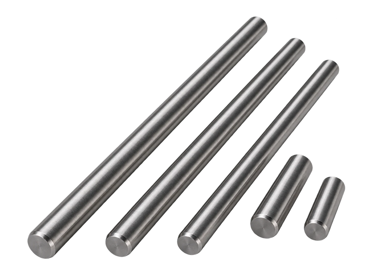
PRECISION PERFORATION PIN ENGINEERING
경강선·피아노선의 직진도, 가이드와 천공 수명
PRECISION PERFORATION PIN ENGINEERING
선재 상태·끝단·가이드·복귀 하중을 연결해 정밀 천공 품질을 관리합니다.
PIN · STRAIGHTNESS · GUIDE · ENDURANCE
가는 천공 핀의 수명은 경도 하나로 결정되지 않습니다. 원선의 제조 상태, 완성 핀의 직진도와 끝단, 가이드의 정렬, 관통·복귀 하중이 함께 작용합니다. 아이디솔루텍은 이 연결을 도면과 검사 기준으로 정리합니다.
재료 선정부터 좌굴 검토·수명 시험까지 연결하여 정밀 천공 핀의 검증 기준을 설명합니다. 시험값은 소재·치수·홀딩·윤활·속도 등 적용 조건과 함께 해석하고 실제 부품의 보증값과 구분합니다.
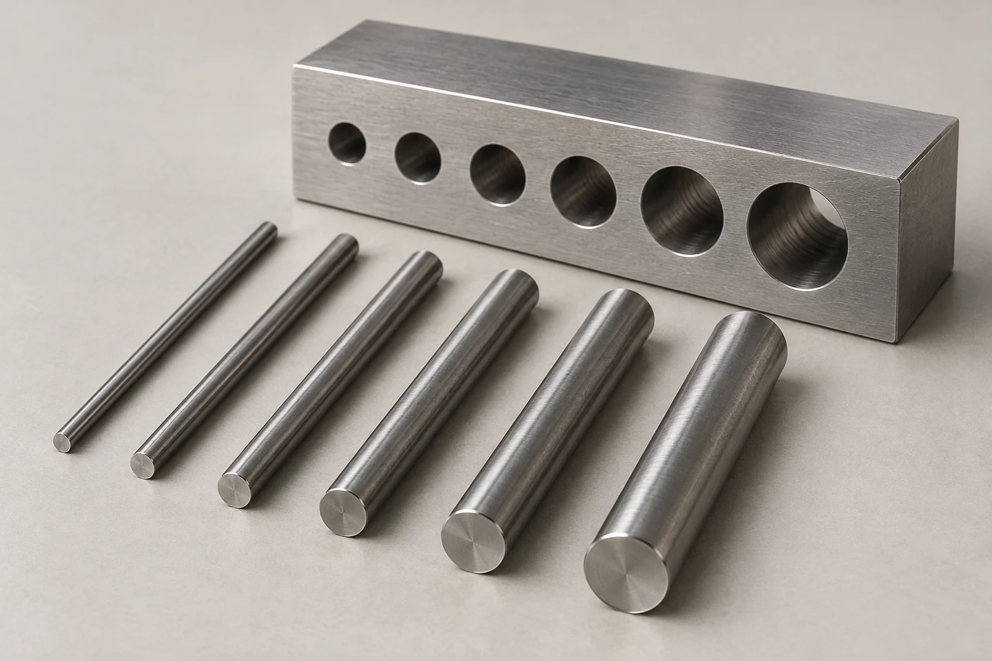
PIN & GUIDE / 선경별 핀과 가이드 블록
천공 하중과 소재 정의
구멍 크기만으로 핀을 선정하지 않습니다.
천공 핀은 작은 단면으로 압축 하중을 전달하면서 소재를 관통하고, 복귀 때에는 마찰과 소재의 탄성 회복을 견딥니다. 같은 직경이라도 금속 박판, 필름, 섬유와 적층재의 파괴 방식이 다르므로 피아노선이라는 재료명만으로 적용 범위를 정할 수 없습니다.
설계 입력에는 피가공재의 재질·두께·적층 수, 천공 형상, 생산 속도와 지지 방법을 포함합니다. 금속의 전단 천공과 날카로운 선단의 관통은 필요한 끝단 형상과 하중 모델이 다릅니다. 먼저 실제 공정이 어느 방식인지 확인해야 합니다.
아이디솔루텍의 검토 기준은 직진도·직경·끝단 품질을 금형의 가이드와 연결하는 것입니다. 도면 합격 핀이라도 비정상적인 편심, 이중 공급이나 스크랩 정체가 있으면 조기에 파손될 수 있으므로 부품과 설비 조건을 함께 관리합니다.
전단·관통 기구 · 재질·두께·적층 고정
지지와 정렬 · 가이드·다이 위치 확인
반복 하중 · 속도·복귀·정지 조건 기록
| 검토 항목 | 기술적 의미 | 검증·관리 기준 |
|---|---|---|
| 피가공재 | 전단·관통 기구 | 재질·두께·적층 고정 |
| 금형 조건 | 지지와 정렬 | 가이드·다이 위치 확인 |
| 생산 이력 | 반복 하중 | 속도·복귀·정지 조건 기록 |
피가공재
기술적 의미
전단·관통 기구
검증·관리 기준
재질·두께·적층 고정
금형 조건
기술적 의미
지지와 정렬
검증·관리 기준
가이드·다이 위치 확인
생산 이력
기술적 의미
반복 하중
검증·관리 기준
속도·복귀·정지 조건 기록
높은 인장강도와 완성 공구 성능은 다른 정보입니다.
피아노선은 일반적으로 냉간 인발로 높은 강도를 얻은 고탄소 강선 계열입니다. ASTM A228/A228M의 공개 범위는 고응력 또는 피로 성능을 요구하는 스프링용 원형 냉간 인발선을 다룹니다. 이 규격 적합성이 천공 공구의 압축·마모 수명을 직접 인증하지는 않습니다.
일본 제조사 자료는 SWP-A·SWP-B·SWP-V와 직선재 공급 형태를 구분합니다. 경강선과 피아노선, 오일템퍼선은 요구 품질과 제조 경로가 다를 수 있으므로 상호 대체 시에는 재료 성적서와 실제 공급 상태를 확인합니다.
입고 기록에는 강종, 선경, 인장 특성, 표면 상태, 코일 또는 직선재, 로트와 후공정을 남깁니다. 규격 간 명칭을 등가 재질로 단순 치환하거나 인장강도를 임의의 HRC 값으로 바꾸지 않습니다. 구매 요구는 완성 핀의 기능 검사와 연결합니다.
원재료 품질 범위 · 판본과 성적서 대조
인발·직선화 이력 · 코일·직선재 구분
완성 핀의 기능 · 시편 가공과 수명 비교
높은 인장강도와 완성 공구 성능은 다른 정보입니다.
원재료 규격의 시험 항목과 완성품의 합격 항목을 별도 표로 관리합니다. 소재 인증서만으로 반복 천공 품질을 승인하지 않습니다.
| 검토 항목 | 기술적 의미 | 검증·관리 기준 |
|---|---|---|
| 규격 | 원재료 품질 범위 | 판본과 성적서 대조 |
| 공급 상태 | 인발·직선화 이력 | 코일·직선재 구분 |
| 대체 검토 | 완성 핀의 기능 | 시편 가공과 수명 비교 |
규격
기술적 의미
원재료 품질 범위
검증·관리 기준
판본과 성적서 대조
공급 상태
기술적 의미
인발·직선화 이력
검증·관리 기준
코일·직선재 구분
대체 검토
기술적 의미
완성 핀의 기능
검증·관리 기준
시편 가공과 수명 비교
재료와 가이드 조합
재료의 우열보다 실패 형태에 맞는 조합이 중요합니다.
가는 강선 핀은 선재 가공성과 정밀 절단이라는 장점이 있지만, 고강도 금속의 장기 천공에는 공구강·고속도강·분말 고속도강·초경 등 다른 후보가 적합할 수 있습니다. 소재 선정은 직경과 물량뿐 아니라 측하중, 끝단 마모와 취성 파손의 비중을 반영해야 합니다.
천공 공구는 내마모성·내압축성·내충격성·피로 성능을 함께 평가합니다. 특히 높은 경도나 탄성계수는 유용한 특성이지만 가이드 오정렬과 충격에 대한 허용도까지 보장하지 않습니다. 경도 하나로 후보를 정렬하면 실제 실패 원인을 놓치기 쉽습니다.
비교 시험은 동일한 끝단 형상·표면·가이드·윤활·피가공재 조건에서 수행합니다. 핀 가격보다 양품 수, 교체 정지 시간과 금형 손상 비용을 묶어 판단합니다. 특수 재료를 적용하기 전에 지지 길이와 공정 불안정을 개선하면 원인 분리가 쉬워집니다.
끝단 소성 변형 · 최대 하중과 단면 확인
직경·날끝 변화 · 중간 회수 시편 비교
편심·충격 손상 · 파면과 설치 이력 조사
재료별 카탈로그 수명 배수는 해당 시험 조건의 결과입니다. 다른 피가공재나 핀 직경에 동일 비율을 적용하지 않습니다.
| 검토 항목 | 기술적 의미 | 검증·관리 기준 |
|---|---|---|
| 압축 | 끝단 소성 변형 | 최대 하중과 단면 확인 |
| 마모 | 직경·날끝 변화 | 중간 회수 시편 비교 |
| 인성 | 편심·충격 손상 | 파면과 설치 이력 조사 |
| 경제성 | 양품당 비용 | 정지·교체·손상 포함 |
압축
기술적 의미
끝단 소성 변형
검증·관리 기준
최대 하중과 단면 확인
마모
기술적 의미
직경·날끝 변화
검증·관리 기준
중간 회수 시편 비교
인성
기술적 의미
편심·충격 손상
검증·관리 기준
파면과 설치 이력 조사
경제성
기술적 의미
양품당 비용
검증·관리 기준
정지·교체·손상 포함
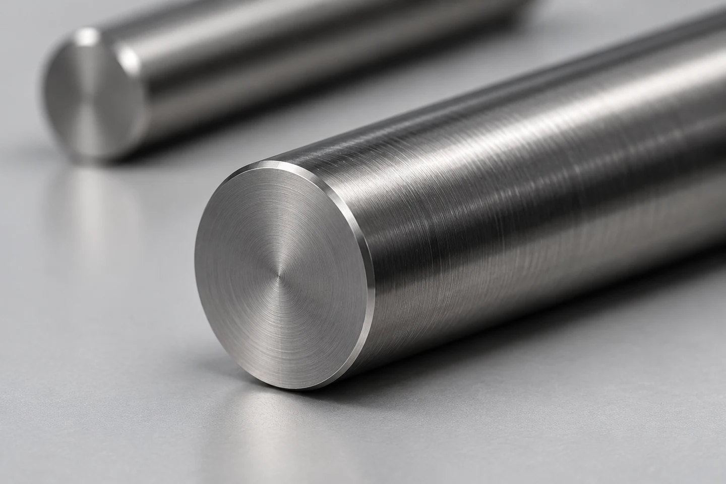
TIP FINISH / 평면 선단과 원주 모서리의 표면 마감
04 / GUIDING & ALIGNMENT
직진도와 동축도는 조립된 상태에서 만납니다.
핀 자체가 곧아도 홀더·부시·다이가 서로 어긋나면 조립하면서 핀이 휘어집니다. 이 상태의 반복 운동은 한쪽 접촉과 마모를 키우고, 천공 순간의 압축을 굽힘과 결합합니다. 원재료 직진도 검사와 금형 정렬 검사는 서로 대체할 수 없습니다.
가이드 구멍을 크게 만들면 끼임은 줄어들 수 있지만 횡방향 지지 기능도 약해집니다. 이 상충관계를 실제 조립 조건에서 확인합니다. 부시의 장착 변형과 접착 간극, 다이 기준의 누적 오차까지 포함해 실조립 상태의 움직임을 확인해야 합니다.
검토 순서는 기준면과 축 설정, 부시 설치 후 내경 확인, 무부하 전 행정 운동, 소재 투입 후 하중 확인으로 나눕니다. 아래 3D에서는 핀·가이드·피가공재의 위치 관계를 살펴볼 수 있습니다. 표시 간극과 움직임은 실제 금형 공차를 대신하지 않습니다.
직진도와 동축도는 조립된 상태에서 만납니다.
| 검토 항목 | 기술적 의미 | 검증·관리 기준 |
|---|---|---|
| 기준축 | 홀더·부시·다이 관계 | 한 기준계로 측정 |
| 가이드 간극 | 마찰과 지지의 균형 | 설치 후 내경 검사 |
| 설치 변형 | 부시 압입·고정 영향 | 무부하 전 행정 확인 |
| 실가공 | 편심 하중 발생 | 방향별 마모·파형 비교 |
기준축
기술적 의미
홀더·부시·다이 관계
검증·관리 기준
한 기준계로 측정
가이드 간극
기술적 의미
마찰과 지지의 균형
검증·관리 기준
설치 후 내경 검사
설치 변형
기술적 의미
부시 압입·고정 영향
검증·관리 기준
무부하 전 행정 확인
실가공
기술적 의미
편심 하중 발생
검증·관리 기준
방향별 마모·파형 비교
슬러그 배출과 스트리퍼 기능을 함께 확인합니다. 표시 형상은 전단면 품질을 예측하지 않습니다.
끝단과 후공정 관리
끝단의 평면·모서리·표면을 서로 다른 특성으로 관리합니다.
평면 선단의 금속 천공 핀에서는 끝단 직각도와 날끝 상태가 최초 접촉을 결정합니다. 비스듬한 연마는 의도하지 않은 한쪽 진입과 측하중을 만들 수 있습니다. 전단각을 의도적으로 부여하는 경우에도 방향·각도·상대 다이를 명확히 지정해야 합니다.
끝단 모서리를 무조건 날카롭게 하거나 크게 둥글리는 방식은 모두 적절하지 않을 수 있습니다. 날끝 강도, 구멍 단면의 버와 침입 하중 사이의 균형을 시험으로 정합니다. 핀 표면의 축 방향 스크래치와 연마 버는 가이드 마찰과 균열 기점 관점에서 확인합니다.
길이 절단, 외경 연삭과 끝단 마감의 순서는 기준면을 유지하도록 설계합니다. 최종 세정 뒤에는 잔류 연마재, 부식과 운송 중 끝단 충돌을 관리합니다. 표면이 반짝인다는 이유만으로 거칠기와 형상 오차가 합격이라고 판단하지 않습니다.
최초 접촉 위치 · 기준축 대비 측정
버·하중·치핑 균형 · 가공품 단면과 비교
마찰·균열 기점 · 확대 검사와 거칠기
핀 끝단의 합격 기준과 가공 구멍의 버 기준을 함께 연결합니다. 연마 조건 변경 뒤에는 길이만 재검사하지 말고 가공 품질도 다시 확인합니다.
| 검토 항목 | 기술적 의미 | 검증·관리 기준 |
|---|---|---|
| 끝단 직각도 | 최초 접촉 위치 | 기준축 대비 측정 |
| 날끝 형상 | 버·하중·치핑 균형 | 가공품 단면과 비교 |
| 표면 결함 | 마찰·균열 기점 | 확대 검사와 거칠기 |
| 취급 | 끝단 충돌·오염 | 분리 포장과 세정 관리 |
끝단 직각도
기술적 의미
최초 접촉 위치
검증·관리 기준
기준축 대비 측정
날끝 형상
기술적 의미
버·하중·치핑 균형
검증·관리 기준
가공품 단면과 비교
표면 결함
기술적 의미
마찰·균열 기점
검증·관리 기준
확대 검사와 거칠기
취급
기술적 의미
끝단 충돌·오염
검증·관리 기준
분리 포장과 세정 관리
냉간 인발재에 후처리를 더할 때는 소재 상태를 다시 확인합니다.
냉간 인발선의 높은 강도는 화학 조성만이 아니라 가공 이력과 연결됩니다. 절단·연삭의 국부 과열이나 별도 열처리가 더해지면 완성 핀의 상태가 원선 성적서와 달라질 수 있습니다. 따라서 원재료 시험값과 후공정 후 검사값을 구분해 기록합니다.
도금이나 경질 코팅은 마찰·부식·마모를 개선하려는 선택지이지만 외경과 끝단 형상도 바꿉니다. 막 두께가 작은 가이드 간극에 미치는 영향, 코팅 전 세정과 공정 온도, 모재의 지지 능력을 함께 검토해야 합니다. 피아노선에 공구강용 조건을 그대로 적용하지 않습니다.
시제품에서는 처리 전후 직경·직진도·표면과 기계적 성능을 비교하고 실제 천공 시험을 이어갑니다. 수명 개선이 표면처리 자체인지 연마·윤활·금형 교체 효과인지 분리합니다. 공정 변경에 따라 검사 항목과 승인 범위도 함께 갱신합니다.
완성품 상태 변화 · 과열 징후와 공정 기록
외경·간극 변화 · 처리 후 치수 재검사
박막 아래 변형 · 하중 조건에서 평가
표면처리의 개선은 동일한 모재·형상·공정 조건에서 비교해야 의미가 있습니다. 코팅 경도만으로 핀의 압축강도나 수명을 환산하지 않습니다.
| 검토 항목 | 기술적 의미 | 검증·관리 기준 |
|---|---|---|
| 가공 열 | 완성품 상태 변화 | 과열 징후와 공정 기록 |
| 막 두께 | 외경·간극 변화 | 처리 후 치수 재검사 |
| 모재 지지 | 박막 아래 변형 | 하중 조건에서 평가 |
| 변경 관리 | 여러 개선의 혼입 | 대조군과 공정 고정 |
가공 열
기술적 의미
완성품 상태 변화
검증·관리 기준
과열 징후와 공정 기록
막 두께
기술적 의미
외경·간극 변화
검증·관리 기준
처리 후 치수 재검사
모재 지지
기술적 의미
박막 아래 변형
검증·관리 기준
하중 조건에서 평가
변경 관리
기술적 의미
여러 개선의 혼입
검증·관리 기준
대조군과 공정 고정
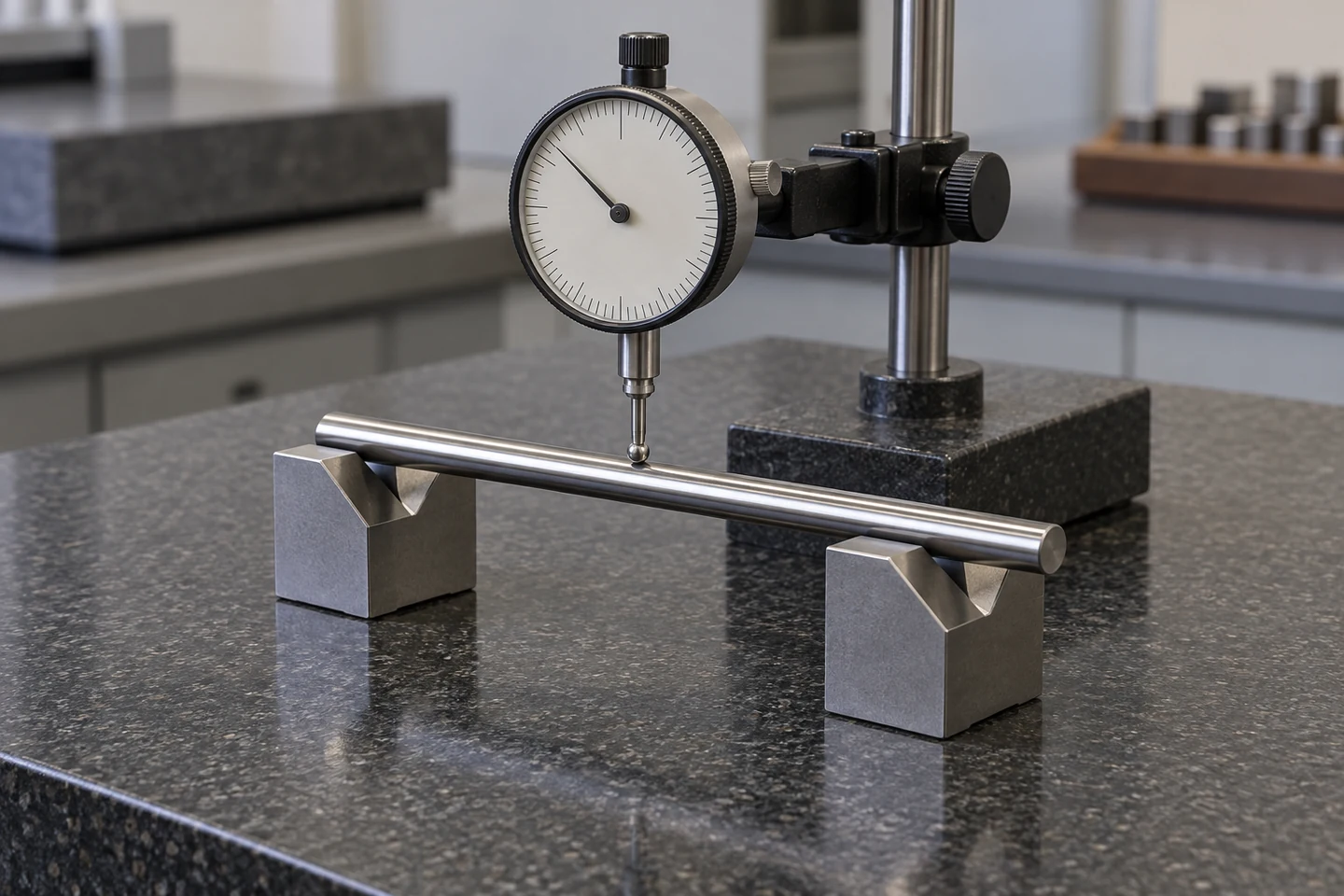
PIN METROLOGY / V블록 지지와 회전 흔들림 검사
복귀와 좌굴 검토
천공이 끝난 뒤에도 파손 하중은 남아 있습니다.
금속 박판은 천공 후 탄성 회복으로 핀을 조일 수 있고, 이때 복귀 마찰과 인장 하중이 증가합니다. 스크랩이 핀 끝단에 붙거나 다이 내부에 쌓이면 다음 행정의 하중 조건도 달라집니다. 관통 시 최대 압축력만 측정하면 이러한 실패 경로를 놓칩니다.
고강도강 천공에서는 좌굴뿐 아니라 복귀 과정의 마모·스트리핑 파손도 분석합니다. 홀딩 조건과 수명 결과는 해당 소재와 형상, 장비 및 시험 조건에 연결되므로 모든 가는 핀의 보편 기준으로 사용하지 않습니다. 복귀 구간을 별도 평가하여 파손 경로를 확인합니다.
하중 파형은 진입·관통·복귀 구간으로 나누고 소재 누름력, 윤활과 배출 상태를 함께 기록합니다. 이상 파형이 나타난 시점의 가공품과 핀을 보존하면 원인 추적이 쉬워집니다. 스크랩 배출 개선 후에도 끝단 부착과 다이 내부 상태를 주기적으로 확인합니다.
소재 회복과 마찰 · 음·양 하중 동시 계측
소재 들림 억제 · 복귀까지 지지 유지
부착·적층 하중 · 배출 경로와 막힘 검사
천공이 끝난 뒤에도 파손 하중은 남아 있습니다.
하중 증가를 모두 소재 경도 변화로 설명하지 않습니다. 복귀 마찰과 스크랩 상태를 먼저 분리하면 불필요한 재료 변경을 줄일 수 있습니다.
| 검토 항목 | 기술적 의미 | 검증·관리 기준 |
|---|---|---|
| 복귀 하중 | 소재 회복과 마찰 | 음·양 하중 동시 계측 |
| 누름 조건 | 소재 들림 억제 | 복귀까지 지지 유지 |
| 스크랩 | 부착·적층 하중 | 배출 경로와 막힘 검사 |
| 이상 분석 | 행정별 원인 분리 | 파형·시편·시간 연결 |
복귀 하중
기술적 의미
소재 회복과 마찰
검증·관리 기준
음·양 하중 동시 계측
누름 조건
기술적 의미
소재 들림 억제
검증·관리 기준
복귀까지 지지 유지
스크랩
기술적 의미
부착·적층 하중
검증·관리 기준
배출 경로와 막힘 검사
이상 분석
기술적 의미
행정별 원인 분리
검증·관리 기준
파형·시편·시간 연결
횡변형은 판독을 위해 확대했습니다. 편심·직진도·마찰이 실제 위험에 영향을 줍니다.
유효 지지 길이와 경계 조건을 먼저 정의합니다.
원형 핀의 단면 2차 모멘트는 직경의 네제곱에 비례하고 이상 탄성 좌굴 하중은 유효 길이의 제곱에 반비례합니다. 같은 재료라도 가이드가 가까워져 자유 길이가 줄면 안정성이 크게 달라지는 이유입니다. 그러나 실제 핀은 초기 휨·편심·유격과 국부 접촉을 가집니다.
아래 식은 곧은 등단면 원형 핀의 탄성 영역과 중심 압축을 가정한 선별 계산입니다. 금속 박판의 천공 하중 근사에는 전단 둘레·두께·전단 저항을 사용합니다. 필름의 첨두 관통이나 동적 충격, 단차 핀과 소성 좌굴에는 별도 모델과 실측이 필요합니다.
예를 들어 d=1 mm, E=200,000 N/mm², K=1을 가정하면 L=20 mm의 이상 좌굴 하중은 약 242 N이고 L=10 mm에서는 약 969 N입니다. 이는 길이 효과를 보이는 계산 예시이며 허용 하중이 아닙니다. 실제 여유도는 결함·피로·충격과 측정된 최대 하중을 반영해 정합니다.
변수와 적용 범위
Pcr: 이상 탄성 좌굴 하중(N), E: 탄성계수(N/mm²), I: 단면 2차 모멘트(mm⁴), K: 유효 길이 계수, L: 자유 길이(mm), d: 직경(mm), t: 소재 두께(mm), τ: 전단 저항(N/mm²). K와 E는 실제 지지와 재료에 맞게 지정합니다. Fcut은 평면 원형 핀의 금속 전단 근사이며 허용 하중·피로 수명 공식이 아닙니다.
3D의 지지 위치 변화는 좌굴 민감도를 살펴보는 용도입니다. 화면의 휨이나 색상은 실물 변형량과 안전계수를 산출한 결과가 아닙니다.
| 검토 항목 | 기술적 의미 | 검증·관리 기준 |
|---|---|---|
| 직경 d | I가 d⁴에 비례 | 최소 실측 직경 사용 |
| 길이 KL | 지지 경계와 자유 길이 | 실조립 지지 위치 반영 |
| 가공 하중 | 전단 근사와 실측 차이 | 피크·복귀 파형 확인 |
| 적용 한계 | 편심·충격·소성 | 추가 해석과 시험 판단 |
직경 d
기술적 의미
I가 d⁴에 비례
검증·관리 기준
최소 실측 직경 사용
길이 KL
기술적 의미
지지 경계와 자유 길이
검증·관리 기준
실조립 지지 위치 반영
가공 하중
기술적 의미
전단 근사와 실측 차이
검증·관리 기준
피크·복귀 파형 확인
적용 한계
기술적 의미
편심·충격·소성
검증·관리 기준
추가 해석과 시험 판단
측정과 파손 분석
회전 흔들림과 중심선 직진도를 구분합니다.
긴 핀의 직경은 한 위치의 마이크로미터 값만으로 충분하지 않습니다. 여러 축 방향 위치와 방향에서 측정해 테이퍼·타원과 국부 손상을 구분합니다. 끝단 근처의 치수는 천공 구멍 품질에, 가이드 구간의 치수는 작동 저항에 서로 다르게 영향을 줍니다.
V블록과 인디케이터를 이용한 회전 측정은 생산 현장에서 유용한 선별법이지만 원형도·지지 위치·표면 상태의 영향도 포함합니다. 측정한 총 흔들림을 그대로 중심선 직진도라고 부르면 서로 다른 기하 특성을 혼동하게 됩니다. 도면의 기준과 측정 방법을 먼저 맞춥니다.
측정력에 의해 휘기 쉬운 핀은 지지 간격·접촉력·온도 안정화를 관리합니다. 비접촉 광학 검사는 작은 끝단과 윤곽 확인에 유용하나 배율·조명·에지 검출 조건을 고정해야 합니다. 수치와 함께 측정 길이, 지지 방법과 불확도를 남깁니다.
회전 흔들림과 중심선 직진도를 구분합니다.
검사 지그의 흔들림과 핀의 흔들림을 분리할 기준 시편을 마련합니다. 측정자 간 차이가 공차에 비해 큰 경우 검사 방법부터 개선합니다.
| 검토 항목 | 기술적 의미 | 검증·관리 기준 |
|---|---|---|
| 외경 | 테이퍼·타원 구분 | 다위치·다방향 측정 |
| 직진도 | 기준축과 평가 길이 | 측정 방법 문서화 |
| 흔들림 | 형상·지지 복합 영향 | 직진도와 구분 표기 |
| 광학 검사 | 날끝·버·윤곽 | 조명과 판정 반복성 확인 |
외경
기술적 의미
테이퍼·타원 구분
검증·관리 기준
다위치·다방향 측정
직진도
기술적 의미
기준축과 평가 길이
검증·관리 기준
측정 방법 문서화
흔들림
기술적 의미
형상·지지 복합 영향
검증·관리 기준
직진도와 구분 표기
광학 검사
기술적 의미
날끝·버·윤곽
검증·관리 기준
조명과 판정 반복성 확인
부러졌다는 결과보다 시작 위치와 발생 시점이 중요합니다.
끝단의 치핑, 길이 방향 긁힘, 가이드 출구의 굽힘과 고정부 파손은 서로 다른 원인을 시사합니다. 같은 파단면이라도 과부하, 반복 피로와 조립 중 손상이 겹칠 수 있으므로 확대 사진만으로 단정하지 않습니다. 핀의 사용 방향과 위치를 보존합니다.
관통 직후 급격한 하중 해방은 압축만의 문제가 아닙니다. 두꺼운 판의 천공에서는 브레이크스루 뒤 인장 충격과 단면 변화에 따른 응력 집중을 검토합니다. 해당 대형 공구의 치수를 가는 핀에 복사하기보다 하중 반전과 고정부 검토의 필요성을 가져옵니다.
분석에는 최종 파단품뿐 아니라 직전의 정상 핀, 가공 구멍과 스크랩을 함께 수집합니다. 파형·윤활·금형 정렬·소재 로트를 시간축으로 묶으면 급격한 사건과 누적 마모를 구분할 수 있습니다. 원인을 수정한 뒤 동일 조건의 재현 시험으로 효과를 확인합니다.
치핑·모서리 마모 · 구멍 버와 연계
긁힘·응착 · 가이드·복귀 마찰 확인
응력 집중·하중 반전 · 단차와 고정 상태 검토
파손품을 연마하거나 세척하기 전에 원상 사진을 확보합니다. 표면 잔류물과 방향 정보는 마찰·응착 원인을 찾는 중요한 단서입니다.
| 검토 항목 | 기술적 의미 | 검증·관리 기준 |
|---|---|---|
| 끝단 손상 | 치핑·모서리 마모 | 구멍 버와 연계 |
| 측면 손상 | 긁힘·응착 | 가이드·복귀 마찰 확인 |
| 고정부 | 응력 집중·하중 반전 | 단차와 고정 상태 검토 |
| 시간 이력 | 돌발·누적 구분 | 사건 전후 시편 보존 |
끝단 손상
기술적 의미
치핑·모서리 마모
검증·관리 기준
구멍 버와 연계
측면 손상
기술적 의미
긁힘·응착
검증·관리 기준
가이드·복귀 마찰 확인
고정부
기술적 의미
응력 집중·하중 반전
검증·관리 기준
단차와 고정 상태 검토
시간 이력
기술적 의미
돌발·누적 구분
검증·관리 기준
사건 전후 시편 보존
수명과 생산 승인
파단까지 버틴 횟수만으로 양산 수명을 정하지 않습니다.
핀의 기능 수명은 파단보다 먼저 끝날 수 있습니다. 구멍 버, 위치, 직경이나 가공 저항이 허용 범위를 벗어나면 아직 곧은 핀이라도 교체 대상입니다. 시험 전에 가공품 품질과 핀 손상의 합격 기준을 각각 명확히 정합니다.
천공 내구 시험에서는 소재·직경·속도·윤활 조건과 버 높이 판정을 함께 기록합니다. 이 방식의 핵심은 수명 숫자에 시험 조건과 종료 기준이 붙어 있다는 점입니다. 다른 재질의 핀에 해당 횟수나 개선 배수를 보증값으로 가져오지 않습니다.
시제품 시험은 정상 조건뿐 아니라 예상 두께·정렬·윤활 편차를 포함합니다. 일정 간격의 회수 검사와 하중 추세를 연결하고 복수 핀·복수 로트의 편차를 봅니다. 예방 교체 주기는 현장 데이터가 쌓일 때까지 시험 최대 수명보다 보수적으로 정합니다.
양품 품질 이탈 · 버·직경·위치 한계
열화 진행 속도 · 핀과 구멍 동시 회수
현장 분산 · 복수 로트·편차 평가
파단까지 버틴 횟수만으로 양산 수명을 정하지 않습니다.
시험 중간에 윤활·다이·가이드가 바뀌면 같은 수명 곡선으로 합치지 않습니다. 변경 시점을 표시하고 원인별로 결과를 분리합니다.
| 검토 항목 | 기술적 의미 | 검증·관리 기준 |
|---|---|---|
| 종료 기준 | 양품 품질 이탈 | 버·직경·위치 한계 |
| 중간 검사 | 열화 진행 속도 | 핀과 구멍 동시 회수 |
| 변동 조건 | 현장 분산 | 복수 로트·편차 평가 |
| 교체 주기 | 예방 보전 | 현장 추세로 갱신 |
종료 기준
기술적 의미
양품 품질 이탈
검증·관리 기준
버·직경·위치 한계
중간 검사
기술적 의미
열화 진행 속도
검증·관리 기준
핀과 구멍 동시 회수
변동 조건
기술적 의미
현장 분산
검증·관리 기준
복수 로트·편차 평가
교체 주기
기술적 의미
예방 보전
검증·관리 기준
현장 추세로 갱신
제작 조건과 사용 조건이 연결돼야 반복 품질을 유지할 수 있습니다.
제작 도면에는 재료와 공급 상태, 직경·길이·직진도·끝단 형상, 표면과 버 기준을 지정합니다. 가이드 구간과 작업 구간을 구분하면 전체 길이에 과도한 공차를 부여하지 않으면서 기능 부위의 관리 수준을 높일 수 있습니다.
승인 자료는 입고 성적서, 완성 핀 측정, 가공품 검사와 실가공 하중·수명 결과를 연결합니다. 재료 공급처, 열 이력, 연마·코팅·가이드 변경은 기능에 영향을 줄 수 있으므로 변경 통보와 재검증 범위를 사전에 합의합니다.
아이디솔루텍에 검토를 요청할 때에는 핀·가이드·다이 도면, 피가공재와 두께, 생산 속도, 현재 불량 사진과 목표 수량을 함께 전달하면 됩니다. 미정 조건은 시제품 단계에서 확인할 항목으로 나누고, 측정 가능한 기준으로 제작과 양산 판단을 진행합니다.
기능 부위별 요구 · 기준·공차·끝단 명확화
원재료와 완성품 연결 · 로트·성적·측정 추적
하중·가이드·윤활 · 시험과 현장 조건 대조
도면상 수치가 아직 정해지지 않은 항목은 임의로 보증하지 않습니다. 초기 시편과 측정 계획을 통해 요구 수준을 구체화합니다.
| 검토 항목 | 기술적 의미 | 검증·관리 기준 |
|---|---|---|
| 도면 | 기능 부위별 요구 | 기준·공차·끝단 명확화 |
| 검사 | 원재료와 완성품 연결 | 로트·성적·측정 추적 |
| 사용 조건 | 하중·가이드·윤활 | 시험과 현장 조건 대조 |
| 변경 승인 | 성능 영향의 관리 | 시편·재시험 범위 합의 |
도면
기술적 의미
기능 부위별 요구
검증·관리 기준
기준·공차·끝단 명확화
검사
기술적 의미
원재료와 완성품 연결
검증·관리 기준
로트·성적·측정 추적
사용 조건
기술적 의미
하중·가이드·윤활
검증·관리 기준
시험과 현장 조건 대조
변경 승인
기술적 의미
성능 영향의 관리
검증·관리 기준
시편·재시험 범위 합의
핀·가이드·다이 도면과 피가공재·두께·적층, 생산 속도·윤활 조건을 함께 보내주세요. 구멍 품질 기준, 현재 마모·파손 이력, 요구 수량·일정에 맞춰 소재 후보와 제작·검증 범위를 검토합니다.
Provide pin, guide and die drawings together with workpiece, thickness, layers, speed and lubrication. Hole-quality requirements, existing wear or fracture records, quantities and timing define material candidates, manufacturing and validation scope.
PRECISION PERFORATION PIN ENGINEERING
Connect wire condition, tip finishing, guidance and withdrawal loads to reliable precision perforation.
PIN · STRAIGHTNESS · GUIDE · ENDURANCE
ENGLISH EDITION
From wire to tip, verified under the actual duty.
The life of a slender perforating pin is not determined by hardness alone. Wire delivery condition, finished straightness and tip quality, guide alignment, entry and withdrawal loads act together. ID SOLUTECH translates these relationships into drawing and inspection decisions.
Connect material selection, buckling screening and endurance verification to the actual precision-perforation task. Interpret test values together with material, dimensions, holding, lubrication and speed, and distinguish them from product guarantees.
PIN & GUIDE / Pin diameters and a guide block
Perforation duty and material identity
Hole diameter alone cannot select a pin.
A small perforation pin transmits compressive force during entry and encounters friction and material recovery during withdrawal. Metal foil, polymer film, fabric and laminates fail differently. A music-wire designation therefore cannot establish a universal range of suitable workpieces.
Define material, thickness, stack count, hole geometry, production speed and support conditions. Shearing a metal sheet with a flat punch differs from piercing with a pointed tool in both tip design and force model. Establish the actual mechanism before setting acceptance limits.
ID SOLUTECH connects pin straightness, diameter and tip quality to the guiding system. A dimensionally acceptable component may still fail early under eccentric loading, double feeding or trapped scrap. Review the part and the machine conditions as one operating system.
Shearing or piercing mechanism. Fix material, thickness and layers
Support and alignment. Verify guide and die position
Repeated loading. Record speed, withdrawal and stops
| Review item | Engineering significance | Verification or control |
|---|---|---|
| Workpiece | Shearing or piercing mechanism | Fix material, thickness and layers |
| Tooling | Support and alignment | Verify guide and die position |
| Duty history | Repeated loading | Record speed, withdrawal and stops |
Workpiece
Engineering significance
Shearing or piercing mechanism
Verification or control
Fix material, thickness and layers
Tooling
Engineering significance
Support and alignment
Verification or control
Verify guide and die position
Duty history
Engineering significance
Repeated loading
Verification or control
Record speed, withdrawal and stops
High tensile strength is not a finished-tool qualification.
Music wire is commonly a high-carbon steel wire strengthened by cold drawing. The public ASTM A228/A228M scope addresses round cold-drawn wire intended for demanding springs. Compliance with that wire specification does not directly qualify compressive performance, wear resistance or life as a perforating tool.
Manufacturer information distinguishes SWP-A, SWP-B, SWP-V and straightened supply variants. Hard-drawn wire, music wire and oil-tempered wire can differ in quality requirements and manufacturing route. Substitution requires the material certificate and the actual delivery condition, not a similar commercial name.
Record grade, diameter, tensile properties, surface condition, coil or straight supply, lot and subsequent processing. Do not casually declare grades equivalent across standards or convert tensile strength into an assumed HRC value. Connect purchasing requirements to functional inspection of the finished pin.
Feedstock quality scope. Check edition and certificate
Drawing and straightening history. Distinguish coil and straight stock
Finished-pin function. Compare trials and endurance
High tensile strength is not a finished-tool qualification.
Maintain separate feedstock and finished-part acceptance schedules. A material certificate alone cannot release repeated-perforation performance.
| Review item | Engineering significance | Verification or control |
|---|---|---|
| Specification | Feedstock quality scope | Check edition and certificate |
| Delivery state | Drawing and straightening history | Distinguish coil and straight stock |
| Substitution | Finished-pin function | Compare trials and endurance |
Specification
Engineering significance
Feedstock quality scope
Verification or control
Check edition and certificate
Delivery state
Engineering significance
Drawing and straightening history
Verification or control
Distinguish coil and straight stock
Substitution
Engineering significance
Finished-pin function
Verification or control
Compare trials and endurance
Material and guide selection
Choose for the failure mode, not a universal material ranking.
Fine wire pins offer convenient stock preparation and precision cutting, but long production runs in strong metals may favor tool steel, high-speed steel, powder high-speed steel or carbide. Selection must reflect lateral loading, edge wear and brittle fracture as well as diameter and volume.
Evaluate wear, compression, impact and fatigue as distinct requirements for punching tools. High hardness or elastic modulus is useful but does not guarantee tolerance of misalignment and shock. Ranking candidates by hardness alone can obscure the mechanism that actually ends service life.
Compare candidates with common tip geometry, finish, guiding, lubrication and workpiece conditions. Judge cost per acceptable part together with replacement downtime and die damage. Improving unsupported length and process stability before changing material makes the benefit of an expensive grade easier to establish.
Plastic tip deformation. Check peak force and section
Diameter and edge evolution. Inspect interrupted specimens
Eccentricity and impact damage. Review fracture and installation
Catalog life ratios belong to the reported test conditions. Do not apply the same multiplier to a different workpiece or pin diameter.
| Review item | Engineering significance | Verification or control |
|---|---|---|
| Compression | Plastic tip deformation | Check peak force and section |
| Wear | Diameter and edge evolution | Inspect interrupted specimens |
| Toughness | Eccentricity and impact damage | Review fracture and installation |
| Economics | Cost per good part | Include downtime and damage |
Compression
Engineering significance
Plastic tip deformation
Verification or control
Check peak force and section
Wear
Engineering significance
Diameter and edge evolution
Verification or control
Inspect interrupted specimens
Toughness
Engineering significance
Eccentricity and impact damage
Verification or control
Review fracture and installation
Economics
Engineering significance
Cost per good part
Verification or control
Include downtime and damage
TIP FINISH / Flat working face and circumferential edge
04 / GUIDING & ALIGNMENT
Straightness and coaxiality meet in the assembled tool.
A straight pin can bend during assembly when its holder, bushing and die do not share an axis. Repeated motion then concentrates contact and wear on one side and adds bending to the piercing load. Feedstock straightness inspection cannot replace alignment inspection of the tooling.
Enlarging the guide bore may reduce binding while weakening lateral support. Verify this tradeoff in the actual installed assembly. Evaluate mounting distortion, adhesive clearance and accumulated datum error through the motion of the installed assembly rather than relying solely on component drawings.
Establish datums, inspect the bore after installation, check unloaded full-stroke travel and then measure loaded operation. The 3D view below shows the relationship among pin, guide and workpiece. Its displayed clearances and motion do not specify production-tool tolerances.
Straightness and coaxiality meet in the assembled tool.
| Review item | Engineering significance | Verification or control |
|---|---|---|
| Datum axis | Holder, guide and die relationship | Measure in one datum system |
| Guide clearance | Friction versus support | Inspect installed bore |
| Mounting distortion | Bushing retention effects | Check unloaded full stroke |
| Loaded operation | Eccentric loading | Compare directional wear and force |
Datum axis
Engineering significance
Holder, guide and die relationship
Verification or control
Measure in one datum system
Guide clearance
Engineering significance
Friction versus support
Verification or control
Inspect installed bore
Mounting distortion
Engineering significance
Bushing retention effects
Verification or control
Check unloaded full stroke
Loaded operation
Engineering significance
Eccentric loading
Verification or control
Compare directional wear and force
Review slug evacuation and stripping together. The geometry does not predict cut-edge quality.
Tip finish and process history
Control face, edge and surface as separate characteristics.
For a flat-ended metal punch, face perpendicularity and edge condition determine first engagement. Unintended grinding tilt can introduce one-sided entry and lateral loading. If a shear angle is intentionally used, specify its direction, magnitude and relationship to the die.
Neither the sharpest possible edge nor a generous radius is universally appropriate. Establish the balance among edge strength, hole burr and penetration load through trials. Review longitudinal scratches and grinding burrs for their effects on guide friction and crack initiation.
Plan cutting, diameter grinding and face finishing so that datums remain controlled. After final cleaning, protect against retained abrasive, corrosion and transport impact. A reflective surface does not demonstrate acceptable roughness, roundness or form error; use suitable measurements for each requirement.
Initial engagement. Measure against the datum axis
Burr, force and chipping balance. Compare with hole sections
Friction and crack initiation. Magnified inspection and texture
Link tip acceptance to the burr criterion of the produced hole. After changing grinding conditions, recheck machining quality as well as overall length.
| Review item | Engineering significance | Verification or control |
|---|---|---|
| Face squareness | Initial engagement | Measure against the datum axis |
| Edge geometry | Burr, force and chipping balance | Compare with hole sections |
| Surface defects | Friction and crack initiation | Magnified inspection and texture |
| Handling | Tip impact and contamination | Separate packaging and cleaning |
Face squareness
Engineering significance
Initial engagement
Verification or control
Measure against the datum axis
Edge geometry
Engineering significance
Burr, force and chipping balance
Verification or control
Compare with hole sections
Surface defects
Engineering significance
Friction and crack initiation
Verification or control
Magnified inspection and texture
Handling
Engineering significance
Tip impact and contamination
Verification or control
Separate packaging and cleaning
Recheck material state after treating cold-drawn stock.
The strength of cold-drawn wire depends on processing history as well as chemistry. Local overheating during cutting or grinding, or a subsequent thermal treatment, may leave the finished pin in a different state from that described by the incoming certificate. Keep these two inspection stages distinct.
Plating and hard coatings can target friction, corrosion or wear, but also alter diameter and edge geometry. Review coating thickness against guide clearance, pretreatment, process temperature and substrate support. A process developed for a tool-steel punch cannot automatically be transferred to music wire.
Compare diameter, straightness, surface state and mechanical behavior before and after treatment, then perform application trials. Separate the treatment benefit from simultaneous changes in grinding, lubrication or tooling. Update the inspection plan and release boundary whenever the manufacturing route changes.
Changed finished condition. Inspect overheating and records
Diameter and clearance shift. Remeasure after treatment
Deformation beneath the film. Evaluate under load
A treatment comparison needs a common substrate, geometry and duty. Coating hardness cannot be converted directly into pin compressive strength or service life.
| Review item | Engineering significance | Verification or control |
|---|---|---|
| Process heat | Changed finished condition | Inspect overheating and records |
| Coating thickness | Diameter and clearance shift | Remeasure after treatment |
| Substrate support | Deformation beneath the film | Evaluate under load |
| Change control | Confounded improvements | Hold conditions and reference samples |
Process heat
Engineering significance
Changed finished condition
Verification or control
Inspect overheating and records
Coating thickness
Engineering significance
Diameter and clearance shift
Verification or control
Remeasure after treatment
Substrate support
Engineering significance
Deformation beneath the film
Verification or control
Evaluate under load
Change control
Engineering significance
Confounded improvements
Verification or control
Hold conditions and reference samples
PIN METROLOGY / V-block support and rotational variation inspection
Withdrawal and buckling
Damage-producing loads remain after penetration.
Elastic recovery of a punched sheet can grip the pin and increase withdrawal friction and tensile loading. A slug adhering to the tip or accumulating inside the die also changes the next stroke. Measuring only the maximum entry compression misses these additional failure routes.
Evaluate buckling, abrasive wear and stripping failure in high-strength-steel punching. Holding conditions and endurance depend on the actual material, pin geometry, equipment and test conditions rather than a universal rule for every fine pin. Evaluate withdrawal as a separate phase.
Divide force records into entry, breakthrough and withdrawal, and retain workholding, lubrication and scrap-removal information. Preserve parts and pins from abnormal events for diagnosis. After improving evacuation, continue periodic checks for tip adhesion and accumulation inside the die.
Recovery and friction. Measure both force directions
Control sheet lift. Maintain support during withdrawal
Adhesion and accumulation. Inspect evacuation and blockage
Damage-producing loads remain after penetration.
Do not attribute every load increase to workpiece hardness. Separating withdrawal friction and scrap behavior can avoid an unnecessary material substitution.
| Review item | Engineering significance | Verification or control |
|---|---|---|
| Withdrawal load | Recovery and friction | Measure both force directions |
| Workholding | Control sheet lift | Maintain support during withdrawal |
| Scrap | Adhesion and accumulation | Inspect evacuation and blockage |
| Diagnosis | Separate stroke phases | Link waveforms, samples and time |
Withdrawal load
Engineering significance
Recovery and friction
Verification or control
Measure both force directions
Workholding
Engineering significance
Control sheet lift
Verification or control
Maintain support during withdrawal
Scrap
Engineering significance
Adhesion and accumulation
Verification or control
Inspect evacuation and blockage
Diagnosis
Engineering significance
Separate stroke phases
Verification or control
Link waveforms, samples and time
Lateral deflection is enlarged. Eccentricity, straightness and friction influence the real risk.
Define effective length and end conditions first.
For a circular pin, second moment of area scales with diameter to the fourth power, while ideal elastic buckling load varies inversely with effective length squared. Moving support closer can therefore strongly improve stability without changing material. Real pins also contain initial curvature, eccentricity, clearance and local contacts.
The equations below screen a straight, uniform circular pin under elastic, concentric compression. The metal-sheet cutting estimate uses shearing perimeter, thickness and shear resistance. Pointed film penetration, impact, stepped geometry and inelastic buckling require different models and measured loads.
As an example, d=1 mm, E=200,000 N/mm² and K=1 give approximately 242 N at L=20 mm and 969 N at L=10 mm. These illustrate length sensitivity rather than allowable loads. Set design margin using imperfections, fatigue, dynamic effects and measured peak force.
Variables and limits
Pcr: ideal elastic buckling load (N); E: elastic modulus (N/mm²); I: second moment (mm⁴); K: effective-length factor; L: free span (mm); d: diameter (mm); t: sheet thickness (mm); τ: shear resistance (N/mm²). Select K and E for the actual support and material. Fcut approximates flat circular metal shearing; neither equation establishes allowable load or fatigue life.
The support-position view helps examine buckling sensitivity. Displayed deflection and color do not calculate physical deformation or a safety factor.
| Review item | Engineering significance | Verification or control |
|---|---|---|
| Diameter d | I varies with d⁴ | Use minimum measured diameter |
| Length KL | Support conditions and free span | Represent installed supports |
| Process force | Estimate versus measurement | Check entry and withdrawal peaks |
| Model limits | Eccentricity, impact and yielding | Add analysis and tests |
Diameter d
Engineering significance
I varies with d⁴
Verification or control
Use minimum measured diameter
Length KL
Engineering significance
Support conditions and free span
Verification or control
Represent installed supports
Process force
Engineering significance
Estimate versus measurement
Verification or control
Check entry and withdrawal peaks
Model limits
Engineering significance
Eccentricity, impact and yielding
Verification or control
Add analysis and tests
Metrology and failure analysis
Distinguish rotational runout from centerline straightness.
One micrometer reading cannot characterize a long pin. Measure multiple axial positions and orientations to separate taper, ovality and localized damage. Dimensions near the working end affect hole quality, while those along the guiding region influence running resistance.
Rotating a pin on V-blocks under an indicator is useful for production screening, but the result also contains roundness, support-position and surface effects. Calling total indicated variation centerline straightness confuses different geometric characteristics. Align the drawing requirement with a defined measurement method.
Control support spacing, probe force and temperature for slender pins that deflect during inspection. Optical measurement can resolve small tips and profiles, but magnification, illumination and edge detection must remain stable. Report measurement length, support arrangement and uncertainty together with the value.
Distinguish rotational runout from centerline straightness.
Use a reference artifact to separate fixture variation from pin variation. If operator differences are large relative to tolerance, improve the measurement method first.
| Review item | Engineering significance | Verification or control |
|---|---|---|
| Diameter | Taper and ovality | Measure positions and directions |
| Straightness | Axis and evaluation length | Document the method |
| Runout | Combined form and support effects | Label separately from straightness |
| Optical inspection | Edge, burr and profile | Verify illumination and repeatability |
Diameter
Engineering significance
Taper and ovality
Verification or control
Measure positions and directions
Straightness
Engineering significance
Axis and evaluation length
Verification or control
Document the method
Runout
Engineering significance
Combined form and support effects
Verification or control
Label separately from straightness
Optical inspection
Engineering significance
Edge, burr and profile
Verification or control
Verify illumination and repeatability
Locate initiation and timing, not merely the broken part.
Tip chipping, longitudinal scoring, bending near the guide exit and failure at the retained end suggest different mechanisms. Overload, fatigue and assembly damage can overlap, so a magnified fracture image alone is rarely decisive. Preserve operating orientation and location for each recovered pin.
Rapid load release at breakthrough is not purely a compression problem. Review tensile shock and stress concentration at section changes in heavy punching tools. The transferable lesson for fine pins is to examine load reversal and retention, rather than copy dimensions from a larger tool.
Collect the preceding sound pin, produced holes and scrap alongside the final failed specimen. Align waveforms, lubrication, tool alignment and workpiece lots on a timeline to separate abrupt events from accumulated wear. Verify the corrective action by repeating the relevant duty under controlled conditions.
Chipping and edge wear. Correlate with hole burr
Scoring and adhesion. Review guide and withdrawal friction
Stress concentration and reversal. Inspect transitions and mounting
Document the original condition before grinding or cleaning failed parts. Residues and orientation are valuable clues to friction and adhesion.
| Review item | Engineering significance | Verification or control |
|---|---|---|
| Tip damage | Chipping and edge wear | Correlate with hole burr |
| Flank damage | Scoring and adhesion | Review guide and withdrawal friction |
| Retention | Stress concentration and reversal | Inspect transitions and mounting |
| Timeline | Sudden versus accumulated damage | Preserve samples around the event |
Tip damage
Engineering significance
Chipping and edge wear
Verification or control
Correlate with hole burr
Flank damage
Engineering significance
Scoring and adhesion
Verification or control
Review guide and withdrawal friction
Retention
Engineering significance
Stress concentration and reversal
Verification or control
Inspect transitions and mounting
Timeline
Engineering significance
Sudden versus accumulated damage
Verification or control
Preserve samples around the event
Endurance and production release
Surviving without fracture does not define production life.
Functional life can end before fracture. Excessive hole burr, position error, diameter drift or process force can require replacement even when a pin remains visibly straight. Define workpiece-quality limits separately from allowable pin damage before endurance testing begins.
Report punching endurance together with material, diameter, speed, lubrication and a burr-height endpoint. Attach test conditions and a stopping criterion to every life value. Do not transfer a count or improvement ratio to a different pin material without validation.
Include expected variation in thickness, alignment and lubrication as well as nominal duty. Combine scheduled specimen inspection with force trends and compare multiple pins and lots. Until field evidence accumulates, set preventive replacement intervals conservatively relative to maximum demonstrated test life.
Loss of acceptable part quality. Burr, diameter and position limits
Damage progression. Inspect pins and holes together
Production scatter. Evaluate multiple lots and deviations
Surviving without fracture does not define production life.
If lubrication, die or guide changes during a test, do not merge the results into one undifferentiated life curve. Mark and separate the change.
| Review item | Engineering significance | Verification or control |
|---|---|---|
| Endpoint | Loss of acceptable part quality | Burr, diameter and position limits |
| Intervals | Damage progression | Inspect pins and holes together |
| Variation | Production scatter | Evaluate multiple lots and deviations |
| Replacement | Preventive maintenance | Update from field trends |
Endpoint
Engineering significance
Loss of acceptable part quality
Verification or control
Burr, diameter and position limits
Intervals
Engineering significance
Damage progression
Verification or control
Inspect pins and holes together
Variation
Engineering significance
Production scatter
Verification or control
Evaluate multiple lots and deviations
Replacement
Engineering significance
Preventive maintenance
Verification or control
Update from field trends
Repeatability requires linked manufacturing and operating requirements.
Specify material and delivery state, diameter, length, straightness, tip form, finish and burr requirements. Distinguishing guided and working regions concentrates control where function requires it without imposing unnecessary tolerances over the entire component.
Link incoming certificates, finished-pin metrology, produced-part inspection and measured load and endurance. Supplier, thermal history, grinding, coating or guide changes can affect function. Agree notification and revalidation boundaries before a change reaches production.
For an ID SOLUTECH review, provide pin, guide and die drawings, workpiece material and thickness, operating speed, current defect photographs and required quantities. Separate unresolved inputs into prototype tasks and use measurable criteria to decide manufacturing and production release.

Requirements by functional region. Define datums, tolerances and tip
Feedstock to finished part. Trace lots and measurements
Load, guide and lubrication. Match trial and field conditions
Do not invent guarantees for unresolved drawing requirements. Establish the target through initial samples and a defined measurement plan.
| Review item | Engineering significance | Verification or control |
|---|---|---|
| Drawing | Requirements by functional region | Define datums, tolerances and tip |
| Inspection | Feedstock to finished part | Trace lots and measurements |
| Operating conditions | Load, guide and lubrication | Match trial and field conditions |
| Change release | Control performance effects | Agree samples and revalidation |
Drawing
Engineering significance
Requirements by functional region
Verification or control
Define datums, tolerances and tip
Inspection
Engineering significance
Feedstock to finished part
Verification or control
Trace lots and measurements
Operating conditions
Engineering significance
Load, guide and lubrication
Verification or control
Match trial and field conditions
Change release
Engineering significance
Control performance effects
Verification or control
Agree samples and revalidation
천공 핀은 선재·끝단·가이드·피가공재·복귀 행정이 연결된 정밀 공구입니다. 소재 강도와 완성품 형상, 실제 하중과 양품 품질을 함께 측정해 안정적인 교체 기준을 정합니다.
01 / 원재료 규격과 완성 공구의 승인 범위를 구분합니다.
02 / 선경·강도·직선화·열 이력을 로트별로 추적합니다.
03 / 홀더·부시·다이의 조립 축을 함께 확인합니다.
04 / 끝단 직각도·모서리·표면을 별도 특성으로 관리합니다.
05 / 좌굴식의 경계 조건과 실제 편심·충격을 분리합니다.
06 / 진입·관통·복귀와 스크랩 배출을 함께 계측합니다.
07 / 가공품의 버·치수 이탈을 수명 종료 기준에 포함합니다.
그렇지 않습니다. 스프링용 선재 규격과 천공 공구의 성능 범위는 다릅니다. 피가공재, 두께, 핀 직경·지지 길이, 마모와 충격 조건을 기준으로 후보 재료를 시험해야 합니다.
이상 탄성 좌굴은 주로 탄성계수와 단면·유효 길이에 의해 결정됩니다. 경도는 압입·마모와 관련된 별도 지표이며, 높은 경도가 오정렬이나 충격에 대한 안전을 보장하지 않습니다.
V블록 회전 측정에는 원형도, 지지 위치와 표면의 영향도 들어갑니다. 중심선 직진도와 동일한 값으로 취급하지 말고 도면 요구에 맞는 방법과 평가 길이를 지정합니다.
끼임이 완화될 수 있지만 횡지지 기능은 약해질 수 있습니다. 먼저 홀더·부시·다이의 축과 설치 변형을 확인한 뒤 마찰과 지지 사이에서 간극을 정해야 합니다.
이상 탄성 중심 압축의 임계값을 계산할 뿐입니다. 초기 휨, 편심, 지지 유격, 소성·피로와 동적 하중을 반영한 별도 여유도 및 실가공 시험이 필요합니다.
구멍의 버, 직경·위치나 하중이 한계를 넘으면 기능 수명이 끝난 상태일 수 있습니다. 파단 여부와 양품 유지 능력을 별도로 평가합니다.
모재의 지지 능력, 처리 온도, 두께에 따른 가이드 간극과 끝단 변화를 함께 검토해야 합니다. 동일 조건 대조 시험으로 실제 효과를 확인합니다.
핀·부시·다이 도면, 피가공재·두께·적층, 생산 속도와 윤활, 목표 구멍 품질, 현재 파손·마모 자료, 수량과 일정을 준비합니다. 미정 항목은 시제품 확인 사항으로 구분합니다.
유효 길이와 지지 조건을 실조립 상태에 연결합니다.
표면 마감과 모서리 품질을 가공 구멍의 버와 비교합니다.
하중 추세와 양품 품질로 교체 시점을 정합니다.
천공 핀피아노선경강선직진도좌굴가이드 부시끝단 연마스트리핑 하중버 높이핀 마모공구 수명
A perforating pin is part of a precision system connecting wire, tip, guide, workpiece and withdrawal. Measure material state, finished geometry, actual loads and acceptable-part quality together to establish a stable replacement criterion.
01 / Separate feedstock specification from finished-tool qualification.
02 / Trace diameter, strength, straightening and thermal history by lot.
03 / Verify the assembled axis of holder, bushing and die.
04 / Control face squareness, edge form and surface separately.
05 / Distinguish ideal buckling assumptions from eccentricity and impact.
06 / Measure entry, breakthrough, withdrawal and scrap behavior.
07 / Include produced-part burr and dimensional drift in the life endpoint.
No. A spring-wire specification and a cutting-tool qualification address different requirements. Test candidates against workpiece, thickness, diameter, support length, wear and impact conditions.
Ideal elastic buckling mainly depends on modulus, section and effective length. Hardness is a separate indicator related to indentation and wear and cannot guarantee resistance to misalignment or shock.
A rotational reading also contains roundness, support and surface effects. Do not treat it automatically as centerline straightness; define a method and evaluation length matching the drawing.
It may reduce binding while weakening lateral support. Check alignment and installation distortion before balancing friction against guiding stiffness.
It gives an ideal elastic critical load under concentric compression. Initial curvature, eccentricity, clearance, yielding, fatigue and dynamic effects require separate margin and application testing.
Yes, if hole burr, diameter, position or process force exceeds the acceptance limit. Structural survival and acceptable-part production are different criteria.
Review substrate support, treatment temperature, thickness-related clearance changes and tip geometry. Establish the actual benefit with a controlled comparison under common conditions.
Provide pin, bushing and die drawings, workpiece and stack details, speed and lubrication, hole-quality targets, existing damage evidence, quantities and timing. Separate unresolved items for prototype verification.
Connect effective length and supports to the installed assembly.
Relate surface and edge condition to produced-hole burr.
Use load trends and acceptable-part quality to set replacement.
Perforation pinsMusic wireHard-drawn wireStraightnessBucklingGuide bushingTip grindingStripping forceBurr heightPin wearTool life
연결 준비 중입니다. 현재 전화 연결을 이용하실 수 있습니다.