SHAFT RETENTION ENGINEERING
샤프트 스냅링·어깨·축방향 간극 설계
SHAFT RETENTION ENGINEERING
링·홈·어깨·상대 부품의 관계를 함께 검토해 축방향 고정을 확인합니다.
SHOULDER · GROOVE · CIRCLIP · ENDPLAY
작은 홈의 위치가 조립품의 움직임을 정합니다.
외부 스냅링으로 상대 부품을 고정하는 샤프트를 중심으로 링 선택, 홈 단면과 끝 여유, 가공 기준과 후처리, 설치·계측·운전 검증을 연결합니다. 정확한 치수와 실제 하중 경로를 함께 확인하는 설계 접근입니다.
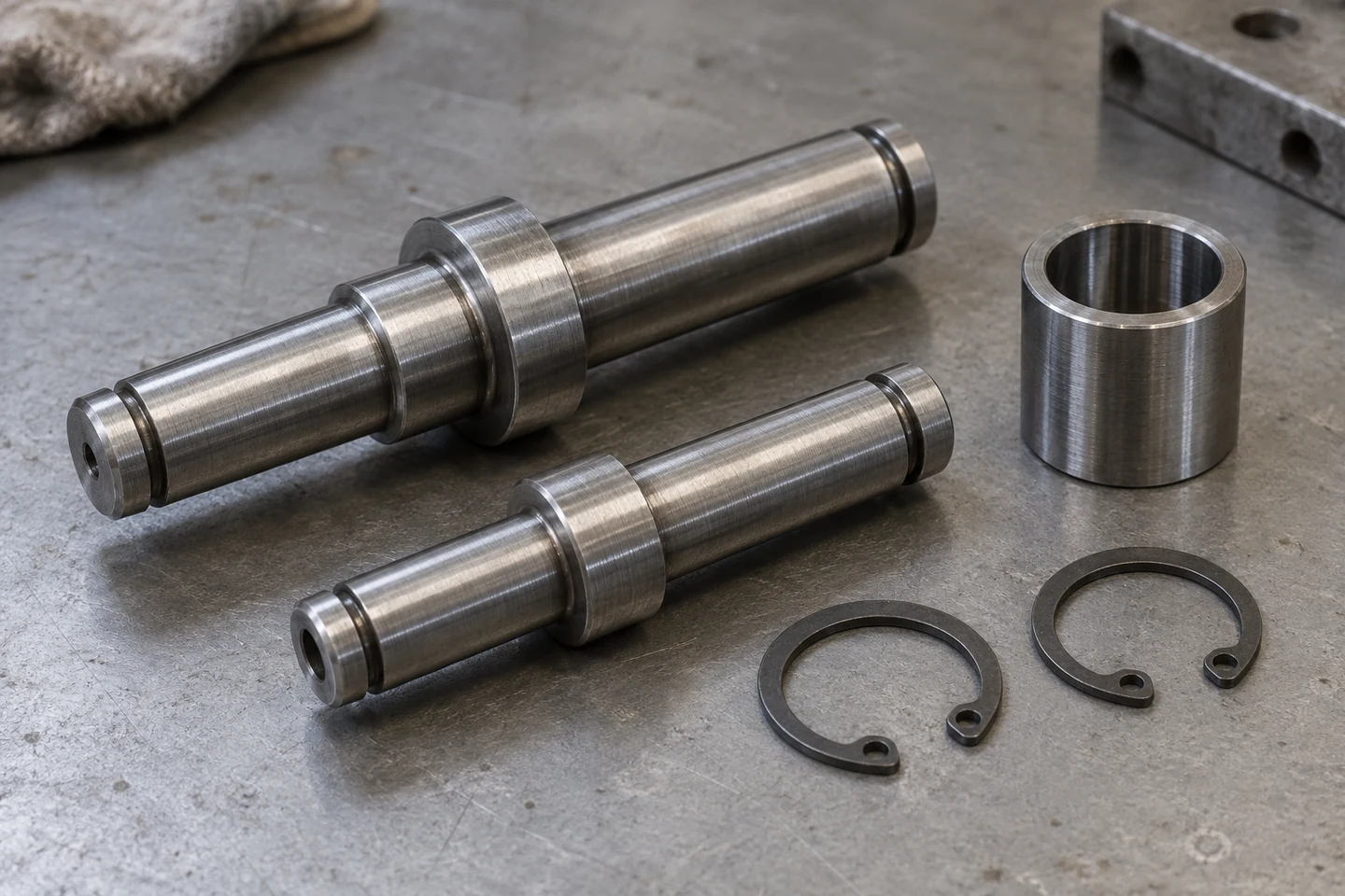
TURNED FAMILY / 홈을 가진 샤프트와 상대 부품
위치와 힘의 관계
홈은 링을 담는 공간이면서 힘을 받는 구조입니다.
샤프트에 끼운 슬리브나 베어링을 고정할 때 먼저 확인할 것은 부품이 어느 방향으로 움직이려 하는가입니다. 한쪽에는 샤프트의 어깨를, 다른 쪽에는 홈에 걸린 링을 두면 두 면이 이동 범위를 정합니다. 링의 존재만 확인하는 대신 상대 부품의 어느 면이 먼저 닿고 어떤 면으로 힘이 전달되는지 조립 단면에서 찾아야 합니다.
스냅링 홈은 단순히 링 두께만큼 파낸 자리가 아닙니다. 바닥 지름은 반지름 방향의 걸림에 영향을 주고, 측벽은 축방향 반력을 받으며, 홈 바깥쪽에 남은 재료는 그 반력을 샤프트 몸체로 전달합니다. 홈 위치와 어깨 위치가 함께 변하면 완성 조립품의 간극도 변하므로 치수들을 독립적인 가공 항목으로만 취급하지 않습니다.
여기서는 축 외경에 설치되는 열린 링과 어깨가 상대 부품을 붙잡는 구성을 중심으로 설명합니다. 하우징 안쪽 링, E형 링, 여러 겹의 스파이럴 링은 조립 방향과 접촉 형상이 다릅니다. 그림의 링 모양은 힘의 관계를 보여 주기 위한 것이며 특정 규격 번호나 실제 제품의 허용 하중을 대신하지 않습니다.
한 방향의 이동 기준 · 상대 부품과 접촉하는 면
반대 방향의 이탈 제한 · 선정 품번과 실제 안착
링 반력을 받는 면 · 위치·형상·남은 재료
| 검토 항목 | 기술적 의미 | 검증·관리 기준 |
|---|---|---|
| 샤프트 어깨 | 한 방향의 이동 기준 | 상대 부품과 접촉하는 면 |
| 스냅링 | 반대 방향의 이탈 제한 | 선정 품번과 실제 안착 |
| 홈 측벽 | 링 반력을 받는 면 | 위치·형상·남은 재료 |
샤프트 어깨
기술적 의미
한 방향의 이동 기준
검증·관리 기준
상대 부품과 접촉하는 면
스냅링
기술적 의미
반대 방향의 이탈 제한
검증·관리 기준
선정 품번과 실제 안착
홈 측벽
기술적 의미
링 반력을 받는 면
검증·관리 기준
위치·형상·남은 재료
하중이 반전되면 같은 면이 계속 받는 것이 아닙니다.
상대 부품이 샤프트 끝으로 밀리면 그 단면이 링의 돌출 영역을 누르고 링은 바깥쪽 홈 측벽에 반력을 전달합니다. 반대로 어깨 쪽으로 밀리면 상대 부품의 반대 단면과 어깨가 주로 힘을 받습니다. 이 차이를 분명히 하면 링의 강도를 높여도 해결되지 않는 어깨면 압흔이나 상대 부품 변형을 별도로 검토할 수 있습니다.
링에 힘을 주는 상대 부품의 모서리가 크게 깎여 있으면 링과 닿는 위치가 바깥쪽으로 이동할 수 있습니다. 그러면 링을 비틀거나 접시 모양으로 변형시키는 경향이 달라집니다. 상대 부품 내경과 모따기, 링의 노출 폭을 조립 단면에 겹쳐 보아 유효한 받침 영역이 남는지 확인하는 과정이 필요합니다.
힘이 샤프트 중심을 벗어나거나 상대 부품이 기울면 둘레에 균등하게 하중이 분포하지 않습니다. 명목상 축방향 힘이 같아도 국부 접촉은 달라지므로 편심, 충격과 반복 작용을 정적인 동심 하중표와 구분합니다. 실제 사용 중 어느 방향과 위치에 최대 반력이 생기는지를 시험 조건과 연결하여 평가합니다.
부품→링→홈 측벽 · 지지 폭과 측벽 상태
부품→어깨→샤프트 · 어깨 접촉과 변형
국부 반력이 증가할 수 있음 · 실제 방향과 반복 조건
하중이 반전되면 같은 면이 계속 받는 것이 아닙니다.
링이 받는 면과 어깨가 받는 면을 검사 도면에서도 구분합니다.
| 검토 항목 | 기술적 의미 | 검증·관리 기준 |
|---|---|---|
| 링 방향 하중 | 부품→링→홈 측벽 | 지지 폭과 측벽 상태 |
| 어깨 방향 하중 | 부품→어깨→샤프트 | 어깨 접촉과 변형 |
| 편심·충격 | 국부 반력이 증가할 수 있음 | 실제 방향과 반복 조건 |
링 방향 하중
기술적 의미
부품→링→홈 측벽
검증·관리 기준
지지 폭과 측벽 상태
어깨 방향 하중
기술적 의미
부품→어깨→샤프트
검증·관리 기준
어깨 접촉과 변형
편심·충격
기술적 의미
국부 반력이 증가할 수 있음
검증·관리 기준
실제 방향과 반복 조건
링 선택과 홈 단면
같은 호칭 지름이라도 홈과 설치 조건은 달라질 수 있습니다.
외부 링을 선택할 때는 샤프트 호칭 지름 외에 링 단면과 두께, 귀의 형상, 조립 방향, 필요한 공구 공간을 함께 확인합니다. 표준 이름이 같거나 외관이 비슷해도 제조사 시리즈와 강화형 여부에 따라 홈 요구가 달라질 수 있습니다. 구매 품번과 도면에 적용한 치수표가 같은 제품을 가리키도록 연결합니다.
축에 끼우는 열린 링은 설치할 때 탄성적으로 벌어졌다가 홈에서 되돌아와야 합니다. 하우징용 링은 반대로 압축하여 넣는 경우가 많으며, 두 종류를 귀의 위치나 색만 보고 교환하면 의도한 걸림이 확보되지 않습니다. 납품 상태의 자유 형상과 설치 후 형상을 구분하여 검사 방법을 정해야 합니다.
작업자가 접근하기 어려운 곳에서는 링 자체보다 조립 공구의 경로가 선택을 제한할 수 있습니다. 플라이어의 끝이 들어갈 공간, 벌릴 때 귀가 움직일 범위, 제거 후 꺼낼 통로까지 조립 검토에 포함합니다. 유지보수가 필요한 제품이라면 첫 조립뿐 아니라 안전하게 분해하고 다시 검증할 방법도 설계 단계에서 정합니다.
실제 사용할 링의 식별 · 동일 시리즈 치수표
홈 요구와 용량에 영향 · 강화형 등 변경 확인
탄성 변형 상태가 다름 · 각 상태별 검사법
대체 링 승인에는 호칭 지름 일치보다 더 많은 항목이 필요합니다.
| 검토 항목 | 기술적 의미 | 검증·관리 기준 |
|---|---|---|
| 구매 품번 | 실제 사용할 링의 식별 | 동일 시리즈 치수표 |
| 단면·두께 | 홈 요구와 용량에 영향 | 강화형 등 변경 확인 |
| 자유·설치 형상 | 탄성 변형 상태가 다름 | 각 상태별 검사법 |
| 공구 공간 | 조립·분해의 실행 가능성 | 귀와 플라이어 이동 |
구매 품번
기술적 의미
실제 사용할 링의 식별
검증·관리 기준
동일 시리즈 치수표
단면·두께
기술적 의미
홈 요구와 용량에 영향
검증·관리 기준
강화형 등 변경 확인
자유·설치 형상
기술적 의미
탄성 변형 상태가 다름
검증·관리 기준
각 상태별 검사법
공구 공간
기술적 의미
조립·분해의 실행 가능성
검증·관리 기준
귀와 플라이어 이동
RING SEATING / 홈에 걸린 링과 슬리브 단면
04 / GROOVE GEOMETRY
링의 걸림과 샤프트의 지지 능력이 같은 단면에 만납니다.
홈 바닥 지름을 낮추면 링이 들어가는 깊이는 늘지만 샤프트의 최소 단면은 줄어듭니다. 깊은 홈을 항상 안전한 방향의 변경으로 보지 말고 선정한 링의 설치 형상과 샤프트 하중을 함께 확인합니다. 특히 중공 샤프트라면 홈 아래에 남는 벽과 내경의 관계가 외경만큼 중요합니다.
홈 폭은 링이 들어갈 공간과 축방향 움직임에 영향을 줍니다. 폭이 좁아 링이 측벽 사이에 걸치면 완전히 내려가지 못할 수 있고, 불필요하게 넓으면 링의 이동과 기울어질 여지가 커집니다. 허용 폭은 링 두께만 보고 임의로 정하지 않고 해당 시리즈의 홈 요구와 조립 간극 설계에 맞춥니다.
바닥 모서리 반경은 가공성과 응력 집중에 관련되지만 링의 모서리가 간섭 없이 앉을 조건도 만족해야 합니다. 홈에서 샤프트 끝까지 남는 여유는 측벽을 지탱하는 재료이므로 외관 정리용 길이가 아닙니다. 제조사 지침의 비율을 사용할 때에도 재료와 하중 조건, 링 종류의 적용 범위를 확인합니다.
링의 걸림과 샤프트의 지지 능력이 같은 단면에 만납니다.
| 검토 항목 | 기술적 의미 | 검증·관리 기준 |
|---|---|---|
| 바닥 지름 | 걸림 깊이와 최소 단면 | 링 요구·중공 잔육 |
| 홈 폭 | 안착과 축방향 이동 | 시리즈 공차와 적층 |
| 모서리 반경 | 간섭과 응력 집중 | 링 모서리와 가공 형상 |
| 끝 여유 | 하중 측벽의 지지 재료 | 재료·하중별 검토 |
바닥 지름
기술적 의미
걸림 깊이와 최소 단면
검증·관리 기준
링 요구·중공 잔육
홈 폭
기술적 의미
안착과 축방향 이동
검증·관리 기준
시리즈 공차와 적층
모서리 반경
기술적 의미
간섭과 응력 집중
검증·관리 기준
링 모서리와 가공 형상
끝 여유
기술적 의미
하중 측벽의 지지 재료
검증·관리 기준
재료·하중별 검토
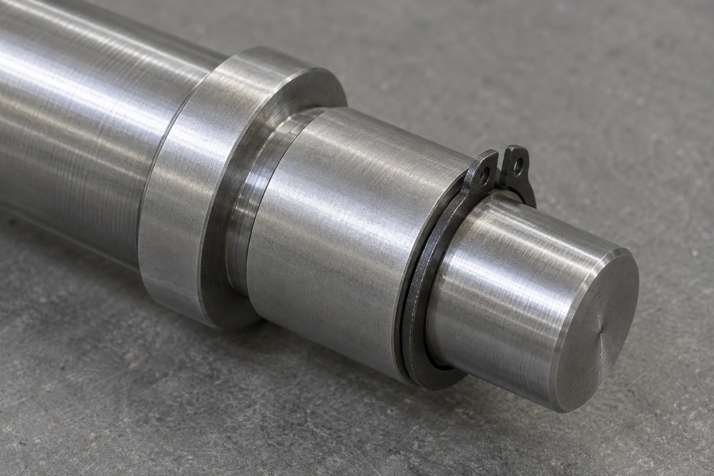
슬리브가 링 아래 면에 닿고 링은 바깥쪽 홈 측벽에 닿습니다. 화살표는 하중 방향이며 변형 계산은 아닙니다.
강도와 가공 기준
강한 링을 선택해도 부드러운 홈 재료가 먼저 변형될 수 있습니다.
축방향 유지 능력은 링 자체와 홈 재료 중 약한 경로의 영향을 받습니다. 링의 전단이나 변형 한계를 확인하는 것과 홈 측벽의 눌림·끝부분 파손을 확인하는 것은 다른 검토입니다. 열처리와 재료 상태가 바뀌면 같은 형상에서도 제한 조건이 달라질 수 있으므로 카탈로그의 기준 재료와 실제 샤프트를 비교합니다.
샤프트가 토크나 굽힘을 받으면 홈은 축방향 유지 기능 외에도 응력 집중을 만드는 형상으로 작용합니다. 원주 홈의 비틀림에서는 홈의 비율과 하중 조건에 따라 국부 응력이 달라집니다. 반원형 시험 홈의 계수를 직사각형 스냅링 홈에 대입하지 않고, 실제 형상과 하중 조합에 맞는 해석 또는 시험을 적용합니다.
정적 하중을 한 번 견딘 결과만으로 반복 충격이나 장기간 진동에 대한 수명을 정할 수는 없습니다. 하중 이력, 잔류 응력과 표면 손상, 부식 환경을 제품 조건에 맞춰 검토합니다. 특히 파손이 허용되지 않는 구조에서는 링 탈락과 샤프트 피로를 서로 다른 고장 모드로 두고 설계 검증의 범위를 정합니다.
전단·굽힘·변형 제한 · 정확한 링 자료
측벽의 눌림과 파손 · 실제 재료·열처리
토크·굽힘의 응력 집중 · 실제 홈 형상 해석
용량 비교표에는 기준 재료와 하중 유형을 생략하지 않습니다.
| 검토 항목 | 기술적 의미 | 검증·관리 기준 |
|---|---|---|
| 링 자체 | 전단·굽힘·변형 제한 | 정확한 링 자료 |
| 홈 재료 | 측벽의 눌림과 파손 | 실제 재료·열처리 |
| 샤프트 단면 | 토크·굽힘의 응력 집중 | 실제 홈 형상 해석 |
| 반복 사용 | 정적 시험과 다른 손상 | 하중 이력과 환경 |
링 자체
기술적 의미
전단·굽힘·변형 제한
검증·관리 기준
정확한 링 자료
홈 재료
기술적 의미
측벽의 눌림과 파손
검증·관리 기준
실제 재료·열처리
샤프트 단면
기술적 의미
토크·굽힘의 응력 집중
검증·관리 기준
실제 홈 형상 해석
반복 사용
기술적 의미
정적 시험과 다른 손상
검증·관리 기준
하중 이력과 환경
공구 폭만 맞추는 가공으로는 조립 위치를 보장할 수 없습니다.
홈 측벽 위치는 상대 부품이 닿는 어깨면과 연결하여 관리하는 편이 조립 기능을 설명하기 쉽습니다. 샤프트 끝면에서 여러 치수를 이어서 지정하면 각각의 공차가 적층되어 필요한 거리의 변동이 커질 수 있습니다. 가공 순서는 실제 고정과 공구 접근에 맞추되 검사 기준이 기능 기준을 재현하도록 정합니다.
좁은 홈을 가공하는 공구는 돌출 길이와 클램핑 상태, 절삭날의 폭·모서리 형상에 민감합니다. 공구가 처지거나 마모되면 측벽의 평행과 바닥 형상이 달라질 수 있으므로 보정값으로 폭만 맞추는 방식에는 한계가 있습니다. 칩 배출과 표면 손상을 확인하며 재료와 공구 계열에 맞는 절삭 조건을 검증합니다.
한 번의 물림으로 어깨와 홈을 가공하면 기준의 연결을 단순화할 수 있지만 모든 부품에서 가능한 것은 아닙니다. 재고정이 필요하다면 기준면의 버와 물림 변형, 회전축의 재현성을 확인하고 완성 상태의 위치 관계를 측정합니다. 프로그램 좌표가 일치한다는 기록과 실제 부품의 치수가 일치한다는 증거를 구분합니다.
어깨와 하중 측벽의 관계 · 직접 치수와 검사 기준
처짐과 진동 억제 · 돌출·물림·날 상태
홈 표면 손상 방지 · 가공 중 칩 흐름
공구 교환 뒤에는 폭뿐 아니라 측벽 위치와 모서리 형상도 확인합니다.
| 검토 항목 | 기술적 의미 | 검증·관리 기준 |
|---|---|---|
| 기준 거리 | 어깨와 하중 측벽의 관계 | 직접 치수와 검사 기준 |
| 공구 고정 | 처짐과 진동 억제 | 돌출·물림·날 상태 |
| 칩 배출 | 홈 표면 손상 방지 | 가공 중 칩 흐름 |
| 재고정 | 기준 관계의 재현 | 완성품 위치 측정 |
기준 거리
기술적 의미
어깨와 하중 측벽의 관계
검증·관리 기준
직접 치수와 검사 기준
공구 고정
기술적 의미
처짐과 진동 억제
검증·관리 기준
돌출·물림·날 상태
칩 배출
기술적 의미
홈 표면 손상 방지
검증·관리 기준
가공 중 칩 흐름
재고정
기술적 의미
기준 관계의 재현
검증·관리 기준
완성품 위치 측정
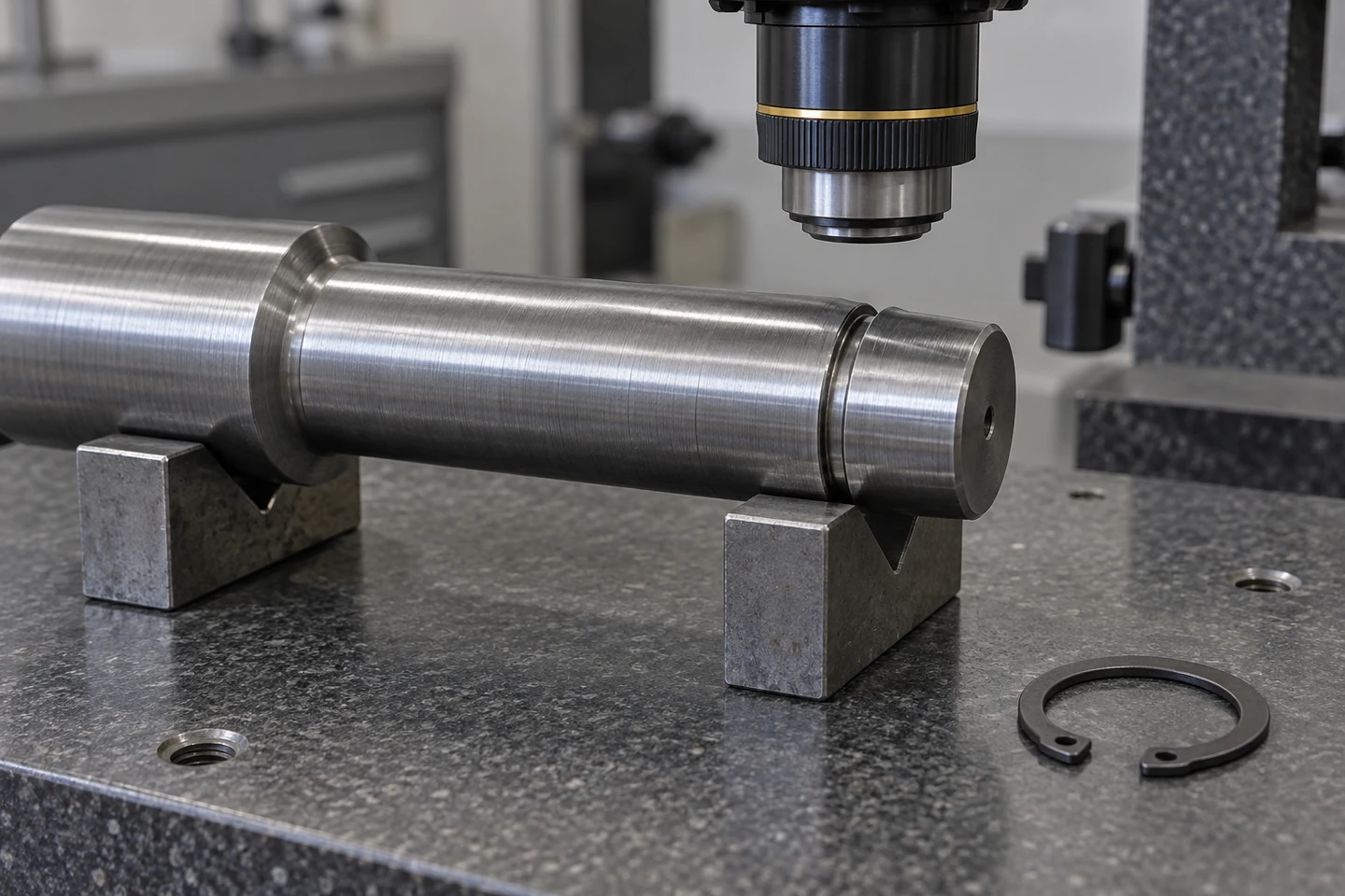
GROOVE INSPECTION / 지지된 샤프트의 홈 확대 관찰
최종 표면과 간극
링이 만나는 것은 가공 직후가 아니라 최종 표면입니다.
홈 입구의 미세한 버는 링이 내려앉는 것을 방해하거나 설치 중 긁혀 입자를 만들 수 있습니다. 반대로 버 제거를 위해 입구 모서리를 크게 둥글게 만들면 링의 유효 걸림이나 상대 부품 접촉 조건이 바뀔 수 있습니다. 허용 모서리 형상을 도면에 연결하고 측벽 자체를 손상시키지 않는 방법을 정합니다.
도금이나 코팅은 홈 바닥과 양쪽 측벽에 형성되어 바닥 지름과 유효 폭을 바꿀 수 있습니다. 실제 두께 분포는 공정과 형상에 따라 달라지므로 외경의 평균 두께만으로 좁은 홈의 상태를 계산해 끝내지 않습니다. 최종 상태의 측정 또는 검증된 공정 관계를 통해 링이 들어갈 형상과 하중을 받을 면을 확인합니다.
열처리 뒤에는 변형과 표면 상태, 경도 분포가 바뀔 수 있습니다. 후가공으로 치수를 회복할 때에도 경화층이나 모서리의 상태가 의도와 달라지지 않는지 검토합니다. 세척 후 홈 안에 남는 절삭 잔류물과 연마 입자를 관리하고, 보관 중 부식이 생긴 부품을 단지 치수가 맞는다는 이유로 승인하지 않습니다.
불완전 안착과 입자 발생 · 최종 확대 관찰
유효 걸림의 변화 · 허용 형상 유지
폭과 바닥 지름 변화 · 홈 내부 최종 상태
링이 만나는 것은 가공 직후가 아니라 최종 표면입니다.
최종 검사 상태와 치수 요구 상태를 도면·성적서에서 일치시킵니다.
| 검토 항목 | 기술적 의미 | 검증·관리 기준 |
|---|---|---|
| 입구 버 | 불완전 안착과 입자 발생 | 최종 확대 관찰 |
| 모서리 처리 | 유효 걸림의 변화 | 허용 형상 유지 |
| 도금·코팅 | 폭과 바닥 지름 변화 | 홈 내부 최종 상태 |
| 열처리·세척 | 강도·표면·청정도 | 후가공과 잔류물 |
입구 버
기술적 의미
불완전 안착과 입자 발생
검증·관리 기준
최종 확대 관찰
모서리 처리
기술적 의미
유효 걸림의 변화
검증·관리 기준
허용 형상 유지
도금·코팅
기술적 의미
폭과 바닥 지름 변화
검증·관리 기준
홈 내부 최종 상태
열처리·세척
기술적 의미
강도·표면·청정도
검증·관리 기준
후가공과 잔류물
확장 공구를 제거하고 링이 홈 안으로 되돌아온 상태입니다. 둘레 전체 안착은 실제 제품에서 별도로 확인합니다.
공차 누적은 설치 여유와 운전 중 이동을 구분하여 계산합니다.
평평한 링이 바깥쪽 홈 측벽에 닿아 있고 상대 부품이 어깨 쪽에 놓인 상태를 생각하면 남는 축방향 간극을 간단한 치수 차로 계산할 수 있습니다. 어깨에서 해당 측벽까지의 거리에서 링 두께와 상대 부품 적층 길이를 뺍니다. 홈의 어느 측벽을 거리 기준으로 사용했는지 먼저 정하지 않으면 같은 기호로 서로 다른 값을 계산하게 됩니다.
설명용으로 거리 L을 10.00±0.03 mm, 링 두께 s를 1.50±0.01 mm, 적층 길이 B를 8.40±0.02 mm로 두면 명목 간극은 0.10 mm입니다. 모든 치수의 극한 조합을 적용한 범위는 0.04~0.16 mm입니다. 이는 제품 권장 간극이 아니라 공차의 방향을 확인하는 예이며 통계 분포를 가정하지 않은 계산입니다.
이 관계는 면들이 평행하고 링과 상대 부품의 탄성변형을 무시하는 기하학적 검토입니다. 경사진 링, 스프링 와셔, 예압 부품이 있거나 온도가 달라지면 추가 변위가 발생합니다. 음의 값이 나오면 자동으로 의도한 예압이라고 해석하지 말고 조립 불능과 변형 가능성을 검토하며, 양의 간극도 사용 중 허용 이동인지 시험으로 확인합니다.
L: 어깨에서 바깥쪽 하중 홈 측벽까지 거리, s: 평평한 링의 축방향 두께, B: 상대 부품 적층 길이, g: 링이 해당 측벽에 닿았을 때 남는 기하학적 간극(모두 mm). 평행면·강체·동일 온도를 가정하며 링 변형, 예압, 열팽창과 동적 이동을 포함하지 않습니다.
간극 계산서에 조립 단면과 하중 방향을 붙여 해석 차이를 줄입니다.
| 검토 항목 | 기술적 의미 | 검증·관리 기준 |
|---|---|---|
| L | 어깨→하중 측벽 거리 | 기준 측벽을 명시 |
| s | 설치 링의 축방향 두께 | 선정품 공차 사용 |
| B | 상대 부품 적층 길이 | 와셔 등 실제 구성 |
| g | 정의한 상태의 잔여 간극 | 극한 조합과 기능 시험 |
L
기술적 의미
어깨→하중 측벽 거리
검증·관리 기준
기준 측벽을 명시
s
기술적 의미
설치 링의 축방향 두께
검증·관리 기준
선정품 공차 사용
B
기술적 의미
상대 부품 적층 길이
검증·관리 기준
와셔 등 실제 구성
g
기술적 의미
정의한 상태의 잔여 간극
검증·관리 기준
극한 조합과 기능 시험
설치와 계측
설치 중 영구 변형은 정상 형상의 링도 약하게 만들 수 있습니다.
외부 링은 샤프트의 통과 지름을 넘을 만큼 벌린 뒤 지정된 홈에서 수축하도록 설치합니다. 지나치게 벌리면 탄성 복원이 부족해질 수 있으므로 선택한 링과 공구에 맞는 확장 제한을 적용합니다. 다른 크기나 시리즈에서 사용한 플라이어 스토퍼 설정을 그대로 쓰지 않고 실제 통과 형상과 제조사 지침을 확인합니다.
링을 귀 구멍으로 조작할 때는 공구 끝이 안정적으로 맞물리고 링이 비틀리지 않도록 접근해야 합니다. 자동 조립의 경우에는 테이퍼 맨드릴과 밀어 넣는 슬리브가 링의 변형과 이동을 제어할 수 있지만, 그 치수는 링과 샤프트에 맞춰 검증해야 합니다. 설명 그림의 각도나 이동 거리를 장비 설계값으로 사용하지 않습니다.
홈에 들어가는 소리가 났다고 둘레 전체가 안착한 것은 아닙니다. 귀 근처 또는 반대쪽 일부가 버 위에 걸쳐 있을 수 있으므로 관찰 가능한 둘레를 확인하고 필요한 위치의 안착 검사를 정합니다. 링이 돌아간다는 사실도 완전한 안착을 증명하지 않으므로 외관·위치·기능 검사 중 어떤 증거가 필요한지 합의합니다.
설치 중 영구 변형은 정상 형상의 링도 약하게 만들 수 있습니다.
설치 기준에는 공구 제한값과 확인할 안착 위치를 함께 포함합니다.
| 검토 항목 | 기술적 의미 | 검증·관리 기준 |
|---|---|---|
| 확장 제한 | 영구 변형 억제 | 선정 링과 통과 지름 |
| 공구 맞물림 | 비틀림·이탈 억제 | 귀 구멍과 팁 상태 |
| 자동 이송 | 변형과 위치의 제어 | 맨드릴·슬리브 검증 |
| 완전 안착 | 실제 홈 걸림 확인 | 둘레 관찰과 위치 검사 |
확장 제한
기술적 의미
영구 변형 억제
검증·관리 기준
선정 링과 통과 지름
공구 맞물림
기술적 의미
비틀림·이탈 억제
검증·관리 기준
귀 구멍과 팁 상태
자동 이송
기술적 의미
변형과 위치의 제어
검증·관리 기준
맨드릴·슬리브 검증
완전 안착
기술적 의미
실제 홈 걸림 확인
검증·관리 기준
둘레 관찰과 위치 검사
측정자가 닿은 표면이 관리하려는 표면과 같아야 합니다.
일반 캘리퍼의 측정면이 좁은 홈 바닥까지 내려가지 못하면 실제 바닥 지름 대신 입구나 모서리를 읽을 수 있습니다. 홈 폭도 둥근 모서리 사이에서 측정하면 정의한 직선 측벽 간격과 달라질 수 있습니다. 접근 가능한 접촉식 측정구, 광학 프로파일 또는 다른 검증된 방법 중 형상에 맞는 조합을 선정합니다.
어깨에서 홈 측벽까지의 거리는 축의 기울기와 기준면의 상태에 영향을 받습니다. 측정 치구가 샤프트를 어떤 면으로 정렬하는지 정하고 여러 방향에서 관찰하여 편심과 국부 결함을 구분합니다. 자동 측정에서는 모서리를 검출하는 알고리즘과 필터 설정까지 결과에 영향을 줄 수 있으므로 승인된 조건을 유지합니다.
측정 불확도는 공차에 비해 충분한 판단 여유가 있는지 검토하는 데 사용합니다. 기준 시편과 반복 측정으로 장비뿐 아니라 고정·작업자·표면의 영향을 확인하고, 경계값의 판정 규칙을 미리 정합니다. 링을 실제로 넣어 보는 확인은 유용하지만 개별 치수와 홈 재료의 적합성을 모두 입증하는 계측을 대체하지 않습니다.
최소 단면과 걸림 깊이 · 측정면의 실제 접근
직선 측벽 사이 거리 · 모서리 영향 배제
기능 기준과의 관계 · 축 정렬·어깨 기준
측정 보고서에는 사용한 표면과 기준을 그림으로 남기면 해석이 명확해집니다.
| 검토 항목 | 기술적 의미 | 검증·관리 기준 |
|---|---|---|
| 바닥 지름 | 최소 단면과 걸림 깊이 | 측정면의 실제 접근 |
| 홈 폭 | 직선 측벽 사이 거리 | 모서리 영향 배제 |
| 축방향 위치 | 기능 기준과의 관계 | 축 정렬·어깨 기준 |
| 판정 여유 | 측정 변동의 영향 | 반복성·불확도·규칙 |
바닥 지름
기술적 의미
최소 단면과 걸림 깊이
검증·관리 기준
측정면의 실제 접근
홈 폭
기술적 의미
직선 측벽 사이 거리
검증·관리 기준
모서리 영향 배제
축방향 위치
기술적 의미
기능 기준과의 관계
검증·관리 기준
축 정렬·어깨 기준
판정 여유
기술적 의미
측정 변동의 영향
검증·관리 기준
반복성·불확도·규칙
운전 검증과 사양 승인
정상 안착에서 시작해 실제 운전 조건까지 검증을 이어갑니다.
조립 검증은 처음의 간극과 안착 상태를 기록한 다음 정의한 방향의 하중을 가하고 변화를 확인하는 방식으로 구성할 수 있습니다. 하중 제거 후 남는 이동이나 홈 측벽의 압흔은 영구 변형의 단서가 됩니다. 시험 지그가 상대 부품을 추가로 받쳐 링의 하중을 우회하지 않는지도 검토해야 합니다.
샤프트가 회전하면 외부 링의 원심력과 상대 부품과의 마찰이 추가로 중요해질 수 있습니다. 링의 회전수 한계는 형상·재료·설치 상태에 따른 별도 검토이며 정적 축방향 용량에서 바로 얻을 수 없습니다. 상대 부품이 링에 대해 미끄러지는 구성은 마모와 링의 이동 가능성도 실제 운동 상태에서 확인합니다.
분해한 링은 제거 과정에서 벌어지거나 비틀렸을 수 있으므로 새 링과 같은 자유 형상을 기대하지 않습니다. 재사용 가능 여부는 선택한 제품과 승인된 절차에 따르고, 홈 측벽의 손상이나 부식도 같이 검사합니다. 유지보수 후의 확인 항목을 초기 조립과 연결하면 교체품만 바꾸고 기존 샤프트 손상을 놓치는 일을 줄일 수 있습니다.
하중 경로의 실제 확인 · 잔류 이동과 측벽 압흔
원심력과 상대 마찰 · 링별 회전수 검토
운전 중 안착 안정성 · 실제 운동과 하중 이력
정상 안착에서 시작해 실제 운전 조건까지 검증을 이어갑니다.
시험 전후의 간극과 사진을 같은 위치에서 비교합니다.
| 검토 항목 | 기술적 의미 | 검증·관리 기준 |
|---|---|---|
| 축방향 부하 | 하중 경로의 실제 확인 | 잔류 이동과 측벽 압흔 |
| 회전 조건 | 원심력과 상대 마찰 | 링별 회전수 검토 |
| 반복·진동 | 운전 중 안착 안정성 | 실제 운동과 하중 이력 |
| 분해 후 | 링과 홈의 손상 확인 | 재사용·교체 기준 |
축방향 부하
기술적 의미
하중 경로의 실제 확인
검증·관리 기준
잔류 이동과 측벽 압흔
회전 조건
기술적 의미
원심력과 상대 마찰
검증·관리 기준
링별 회전수 검토
반복·진동
기술적 의미
운전 중 안착 안정성
검증·관리 기준
실제 운동과 하중 이력
분해 후
기술적 의미
링과 홈의 손상 확인
검증·관리 기준
재사용·교체 기준
샤프트 단품의 합격과 조립 기능의 합격을 연결합니다.
발주 도면에는 링의 품번과 적용 규격, 홈 바닥 지름과 폭, 하중 측벽 위치, 어깨 기준, 모서리와 최종 표면 상태를 묶어 지정합니다. 상대 부품의 내경과 단면 모따기가 빠지면 링에 힘이 전달되는 위치를 검토할 수 없습니다. 필요한 끝 여유와 중공 잔육은 재료 및 사용 하중 검토와 함께 남깁니다.
양산 전에는 치수·소재·표면 성적과 실제 링의 안착, 간극, 하중 시험 결과가 같은 개정을 가리키는지 확인합니다. 홈 공구나 코팅, 링 공급처가 변경되면 영향받는 인터페이스부터 재검증합니다. 부품 번호가 같다는 이유만으로 다른 두께나 다른 설치 공구 설정을 허용하지 않도록 변경 책임을 명확히 합니다.
결론적으로 안정된 축방향 고정은 작은 링 하나의 성능이 아니라 어깨와 상대 부품, 링과 홈 측벽이 완성하는 하중 경로의 결과입니다. 올바른 품번에서 출발해 최종 형상을 측정하고 설치 변형을 제한하며 실제 운전 조건을 검증해야 합니다. 이 과정을 연결하면 홈의 치수 관리가 조립품의 유지 기능으로 이어집니다.
링·홈·상대 부품의 연결 · 동일 개정과 품번
실제 설치 표면의 적합성 · 후처리 상태 검사
안착과 탄성 복원 · 공구 제한과 확인점
검토 자료에는 샤프트 단품도와 상대 부품 단면, 사용 하중을 함께 포함합니다.
| 검토 항목 | 기술적 의미 | 검증·관리 기준 |
|---|---|---|
| 조립 사양 | 링·홈·상대 부품의 연결 | 동일 개정과 품번 |
| 최종 치수 | 실제 설치 표면의 적합성 | 후처리 상태 검사 |
| 설치 관리 | 안착과 탄성 복원 | 공구 제한과 확인점 |
| 기능 승인 | 운전 조건에서 유지 | 방향·회전·반복 시험 |
조립 사양
기술적 의미
링·홈·상대 부품의 연결
검증·관리 기준
동일 개정과 품번
최종 치수
기술적 의미
실제 설치 표면의 적합성
검증·관리 기준
후처리 상태 검사
설치 관리
기술적 의미
안착과 탄성 복원
검증·관리 기준
공구 제한과 확인점
기능 승인
기술적 의미
운전 조건에서 유지
검증·관리 기준
방향·회전·반복 시험
샤프트와 상대 부품 도면, 링 품번, 재료·후처리, 축방향 하중·회전수, 간극과 검사 요구를 보내 주세요.
Provide shaft and mating drawings, ring part number, material and finish, axial loads and speed, clearance and inspection requirements.
SHAFT RETENTION ENGINEERING
Review ring, groove, shoulder and retained component together to establish axial retention.
SHOULDER · GROOVE · CIRCLIP · ENDPLAY
ENGLISH EDITION
Connect groove dimensions to the assembly load path.
A small groove determines how the assembly can move.
For shafts using an external retaining ring, connect ring selection, groove section and end margin with machining datums, finishing, installation, measurement and service verification. Review dimensional conformance together with the actual load path.
TURNED FAMILY / Grooved shafts and mating components
Location and reaction paths
A groove both locates the ring and receives its load.
For a sleeve or bearing mounted on a shaft, first identify the direction in which it tends to move. A shaft shoulder on one side and a ring seated in a groove on the other establish its travel limits. Rather than merely confirming that a ring is present, locate the first contacting faces and follow the reaction through the assembly section.
A retaining groove is more than a recess equal to the ring thickness. Its root diameter affects radial engagement, its flank receives axial reaction, and the remaining material beyond it transfers that reaction into the shaft. Groove and shoulder positions also determine assembly clearance and should not be treated only as independent machining dimensions.
This discussion focuses on an external split ring and shoulder retaining a mating component. Internal housing rings, E-rings and multi-turn spiral rings have different installation directions and contact geometry. The illustrative ring explains the load relationship; it does not substitute for a specified series or its allowable capacity.
Locates one travel limit. Face contacting the retained part
Limits separation in the other direction. Selected part and actual seating
Receives the ring reaction. Position, geometry and remaining material
| Review item | Engineering significance | Verification or control |
|---|---|---|
| Shaft shoulder | Locates one travel limit | Face contacting the retained part |
| Retaining ring | Limits separation in the other direction | Selected part and actual seating |
| Groove flank | Receives the ring reaction | Position, geometry and remaining material |
Shaft shoulder
Engineering significance
Locates one travel limit
Verification or control
Face contacting the retained part
Retaining ring
Engineering significance
Limits separation in the other direction
Verification or control
Selected part and actual seating
Groove flank
Engineering significance
Receives the ring reaction
Verification or control
Position, geometry and remaining material
Load reversal changes which surfaces carry the reaction.
When the retained component moves toward the shaft end, its face presses on the exposed ring, which reacts against the outboard groove flank. Reverse motion mainly loads the opposite component face and the shaft shoulder. This distinction separates problems such as shoulder indentation or component distortion that cannot be solved simply by increasing ring strength.
A large chamfer on the retained component can move its contact with the ring radially outward. This changes the tendency to twist or dish the ring. Overlay the component bore, chamfer and exposed ring width in the assembly section to verify that an effective bearing region remains.
An eccentric force or tilted component does not load the circumference uniformly. The same nominal axial force can therefore produce a different local contact condition. Separate eccentric, impact and repeated loads from static concentric catalog ratings, and connect the largest service reaction direction and position to the qualification test.
Component to ring to groove flank. Bearing width and flank condition
Component to shoulder to shaft. Shoulder contact and distortion
Can concentrate reaction locally. Actual direction and duty cycle
Load reversal changes which surfaces carry the reaction.
Keep ring-side and shoulder-side bearing faces distinct in inspection drawings.
| Review item | Engineering significance | Verification or control |
|---|---|---|
| Toward the ring | Component to ring to groove flank | Bearing width and flank condition |
| Toward the shoulder | Component to shoulder to shaft | Shoulder contact and distortion |
| Eccentricity and impact | Can concentrate reaction locally | Actual direction and duty cycle |
Toward the ring
Engineering significance
Component to ring to groove flank
Verification or control
Bearing width and flank condition
Toward the shoulder
Engineering significance
Component to shoulder to shaft
Verification or control
Shoulder contact and distortion
Eccentricity and impact
Engineering significance
Can concentrate reaction locally
Verification or control
Actual direction and duty cycle
Ring selection and groove section
The same nominal diameter does not imply the same groove or installation.
External-ring selection includes section shape, thickness, lug geometry, installation direction and tool clearance as well as nominal shaft diameter. Similar appearances or standard names do not eliminate differences between series and reinforced versions. Link the purchased part number to the exact dimensional data used on the drawing.
A split external ring must expand elastically during installation and recover into the groove. A housing ring is commonly compressed for insertion, and the two cannot be substituted based on lug appearance or color. Distinguish the as-supplied free shape from the installed shape when defining inspection.
In restricted spaces, the installation-tool path can constrain selection more than the ring itself. Check access for plier tips, the sweep of the expanding lugs and the removal path. For serviceable products, establish how the assembly can be dismantled and reverified as well as how it is first installed.
Identifies the actual ring. Matching series data
Affect groove requirements and capacity. Check reinforced variants
Different elastic states. State-specific inspection
Approve substitutes through the full interface requirements, not nominal diameter alone.
| Review item | Engineering significance | Verification or control |
|---|---|---|
| Purchased part number | Identifies the actual ring | Matching series data |
| Section and thickness | Affect groove requirements and capacity | Check reinforced variants |
| Free and installed shape | Different elastic states | State-specific inspection |
| Tool clearance | Enables installation and removal | Lug and plier movement |
Purchased part number
Engineering significance
Identifies the actual ring
Verification or control
Matching series data
Section and thickness
Engineering significance
Affect groove requirements and capacity
Verification or control
Check reinforced variants
Free and installed shape
Engineering significance
Different elastic states
Verification or control
State-specific inspection
Tool clearance
Engineering significance
Enables installation and removal
Verification or control
Lug and plier movement
RING SEATING / Ring engagement beside the sleeve face
04 / GROOVE GEOMETRY
Ring engagement and shaft support meet in the same section.
Reducing the groove root diameter increases recess depth but reduces the minimum shaft section. A deeper groove is therefore not automatically a safer modification. Review the installed ring shape together with shaft loading. For a hollow shaft, the remaining wall beneath the groove matters as much as the outside diameter.
Groove width affects both ring entry and axial movement. A narrow groove can hold the ring between its flanks before full seating, while unnecessary width permits more movement and inclination. Set the allowable width using the selected series requirements and assembly-clearance design rather than ring thickness alone.
Root corner radius concerns machining and stress concentration, but must also let the ring corner seat without interference. The end margin beyond the groove is structural material supporting the loaded flank. Any catalog ratio must be used within its stated material, load and ring-family conditions rather than treated as a universal rule.
Ring engagement and shaft support meet in the same section.
| Review item | Engineering significance | Verification or control |
|---|---|---|
| Root diameter | Engagement depth and minimum section | Ring requirements and hollow-shaft wall |
| Groove width | Seating and axial movement | Series tolerance and stack |
| Corner radius | Interference and stress concentration | Ring edge and machined form |
| End margin | Supports the loaded flank | Material- and load-specific review |
Root diameter
Engineering significance
Engagement depth and minimum section
Verification or control
Ring requirements and hollow-shaft wall
Groove width
Engineering significance
Seating and axial movement
Verification or control
Series tolerance and stack
Corner radius
Engineering significance
Interference and stress concentration
Verification or control
Ring edge and machined form
End margin
Engineering significance
Supports the loaded flank
Verification or control
Material- and load-specific review
The sleeve meets the ring, which meets the outboard loaded groove flank. The arrow indicates load direction, not calculated deformation.
Strength and machining datums
A stronger ring does not prevent a softer groove from deforming first.
Axial retention is limited by the weaker relevant path through the ring and groove material. Ring shear or deformation and groove-flank yielding or end failure are separate checks. Heat treatment and material condition can change the limiting case without changing geometry, so compare catalog assumptions with the actual shaft.
Under torque or bending, the groove also acts as a stress concentrator beyond its retention function. Local stress around a circumferential groove under torsion depends on its geometry and loading conditions. Do not apply a coefficient from a semicircular specimen directly to a rectangular retaining-ring groove; use analysis or tests appropriate to the actual shape and combined loading.
Surviving one static load does not establish life under repeated impact or sustained vibration. Evaluate load history, residual stress, surface damage and corrosion according to the product environment. Where separation is unacceptable, treat ring disengagement and shaft fatigue as distinct failure modes when setting the verification scope.
Shear, bending and deformation limits. Exact ring data
Flank yielding and failure. Actual material and heat treatment
Stress concentration in torque and bending. Actual groove analysis
Keep material assumptions and load type visible in capacity comparisons.
| Review item | Engineering significance | Verification or control |
|---|---|---|
| Ring itself | Shear, bending and deformation limits | Exact ring data |
| Groove material | Flank yielding and failure | Actual material and heat treatment |
| Shaft section | Stress concentration in torque and bending | Actual groove analysis |
| Repeated service | Damage beyond static testing | Load history and environment |
Ring itself
Engineering significance
Shear, bending and deformation limits
Verification or control
Exact ring data
Groove material
Engineering significance
Flank yielding and failure
Verification or control
Actual material and heat treatment
Shaft section
Engineering significance
Stress concentration in torque and bending
Verification or control
Actual groove analysis
Repeated service
Engineering significance
Damage beyond static testing
Verification or control
Load history and environment
Correct tool width alone cannot establish assembly location.
Controlling the loaded groove flank relative to the component-bearing shoulder gives a direct description of assembly function. Chaining several dimensions from the shaft end can accumulate tolerance in the distance that matters. Plan operations for practical workholding and access while ensuring that inspection reproduces the functional datum relationship.
A narrow grooving tool is sensitive to overhang, clamping, edge width and corner form. Deflection or wear can change flank alignment and root geometry, so width compensation alone has limits. Verify chip evacuation and surface condition using cutting parameters appropriate to the material and tooling family.
Machining the shoulder and groove in one setup can simplify datum transfer, but is not feasible for every component. If reclamping is required, check datum burrs, holding distortion and rotational-axis repeatability, then measure the finished relationship. Matching program coordinates and conforming physical dimensions are different kinds of evidence.
Shoulder to loaded flank. Direct dimension and inspection datum
Controls deflection and vibration. Overhang, clamp and edge
Protects groove surfaces. Observe chip flow during machining
After tool changes, check flank location and corner form as well as width.
| Review item | Engineering significance | Verification or control |
|---|---|---|
| Functional distance | Shoulder to loaded flank | Direct dimension and inspection datum |
| Tool holding | Controls deflection and vibration | Overhang, clamp and edge |
| Chip evacuation | Protects groove surfaces | Observe chip flow during machining |
| Reclamping | Reproduces datum relationships | Measure the finished location |
Functional distance
Engineering significance
Shoulder to loaded flank
Verification or control
Direct dimension and inspection datum
Tool holding
Engineering significance
Controls deflection and vibration
Verification or control
Overhang, clamp and edge
Chip evacuation
Engineering significance
Protects groove surfaces
Verification or control
Observe chip flow during machining
Reclamping
Engineering significance
Reproduces datum relationships
Verification or control
Measure the finished location
GROOVE INSPECTION / Magnified groove on a supported shaft
Final surfaces and clearance
The ring encounters the finished surface, not the as-cut one.
A small entry burr can prevent full seating or produce particles as the ring scrapes over it. Conversely, excessive rounding during deburring can change effective engagement or component contact. Define the permitted edge form and choose a method that preserves the load-bearing flank.
Plating or coating on the groove root and both flanks can alter root diameter and usable width. Thickness distribution depends on process and geometry, so the average thickness measured on an outside diameter does not fully describe a narrow groove. Verify the final interface through measurement or a qualified process relationship.
Heat treatment can change distortion, surface condition and hardness distribution. If finish machining restores dimensions, also review whether it changes the intended hardened layer or edge condition. Control chips and abrasive residue after cleaning, and do not accept a corroded groove solely because its measured dimensions remain within tolerance.
Incomplete seating and particles. Final magnified inspection
Changes effective engagement. Preserve permitted form
Change width and root diameter. Final internal groove condition
The ring encounters the finished surface, not the as-cut one.
Match the specified dimensional condition to the condition recorded in inspection.
| Review item | Engineering significance | Verification or control |
|---|---|---|
| Entry burr | Incomplete seating and particles | Final magnified inspection |
| Edge treatment | Changes effective engagement | Preserve permitted form |
| Plating and coating | Change width and root diameter | Final internal groove condition |
| Heat treatment and cleaning | Affect strength, surface and cleanliness | Finish machining and residue |
Entry burr
Engineering significance
Incomplete seating and particles
Verification or control
Final magnified inspection
Edge treatment
Engineering significance
Changes effective engagement
Verification or control
Preserve permitted form
Plating and coating
Engineering significance
Change width and root diameter
Verification or control
Final internal groove condition
Heat treatment and cleaning
Engineering significance
Affect strength, surface and cleanliness
Verification or control
Finish machining and residue
The expansion tool is removed and the ring returns into the groove. Complete circumferential seating still requires verification on the actual product.
Distinguish geometric endplay from installation clearance and operating movement.
For a flat ring against the outboard groove flank and the retained stack against the shoulder, the remaining axial clearance follows from a simple dimension chain. Subtract ring thickness and retained-stack length from the shoulder-to-loaded-flank distance. Identify the flank first; otherwise identical symbols can describe different distances.
As an illustration, let L be 10.00 ± 0.03 mm, ring thickness s be 1.50 ± 0.01 mm and stack length B be 8.40 ± 0.02 mm. Nominal clearance is 0.10 mm and the full extreme combination spans 0.04–0.16 mm. This demonstrates tolerance direction rather than recommending a product clearance, and assumes no statistical distribution.
The relation is geometric and assumes parallel faces while neglecting elastic deformation. Inclined rings, spring washers, preload elements and temperature changes introduce additional displacement. A negative result is not automatically a designed preload: assess assembly interference and distortion. A positive result still needs evaluation against permitted service movement.
L: shoulder-to-outboard loaded-flank distance; s: flat-ring axial thickness; B: retained-stack length; g: remaining geometric clearance with the ring against that flank (all mm). Assumes parallel rigid faces at one temperature; excludes ring deflection, preload, thermal expansion and dynamic movement.
Attach the assembly section and load direction to the clearance calculation.
| Review item | Engineering significance | Verification or control |
|---|---|---|
| L | Shoulder-to-loaded-flank distance | Identify the reference flank |
| s | Axial thickness of the installed ring | Use selected-part tolerance |
| B | Length of the retained stack | Include the actual washers and parts |
| g | Clearance in the defined condition | Extreme combinations and functional test |
L
Engineering significance
Shoulder-to-loaded-flank distance
Verification or control
Identify the reference flank
s
Engineering significance
Axial thickness of the installed ring
Verification or control
Use selected-part tolerance
B
Engineering significance
Length of the retained stack
Verification or control
Include the actual washers and parts
g
Engineering significance
Clearance in the defined condition
Verification or control
Extreme combinations and functional test
Installation and measurement
Permanent set during installation can compromise an otherwise conforming ring.
Expand an external ring enough to clear the shaft passage diameter, then let it contract into the specified groove. Excessive expansion can leave inadequate elastic recovery. Apply limits suited to the selected ring and tool rather than reusing a plier-stop setting from a different size or series.
When manipulating lug holes, ensure stable tip engagement and avoid twisting the ring. Automated equipment can use a tapered mandrel and pushing sleeve to control deformation and transfer, but those dimensions require qualification for the ring and shaft. Angles or travel shown in explanatory graphics are not machine-design values.
An installation click does not prove full circumferential seating. A sector near the lugs or on the opposite side may remain on a burr. Inspect the accessible circumference and define any required local seating checks. The ability to rotate a ring is also not sufficient evidence of complete engagement.
Permanent set during installation can compromise an otherwise conforming ring.
Include both tool limits and seating-check locations in installation instructions.
| Review item | Engineering significance | Verification or control |
|---|---|---|
| Expansion limit | Avoids permanent set | Selected ring and passage diameter |
| Tool engagement | Avoids twist and release | Lug holes and tip condition |
| Automated transfer | Controls deformation and position | Qualified mandrel and sleeve |
| Full seating | Confirms actual groove engagement | Circumferential and location checks |
Expansion limit
Engineering significance
Avoids permanent set
Verification or control
Selected ring and passage diameter
Tool engagement
Engineering significance
Avoids twist and release
Verification or control
Lug holes and tip condition
Automated transfer
Engineering significance
Controls deformation and position
Verification or control
Qualified mandrel and sleeve
Full seating
Engineering significance
Confirms actual groove engagement
Verification or control
Circumferential and location checks
The contacted surface must be the one the requirement actually controls.
If ordinary caliper jaws cannot reach a narrow root, they may read the entry or corner rather than the actual groove diameter. Measuring width between rounded edges can likewise differ from the defined straight-flank spacing. Select accessible contact tools, optical profiles or other qualified methods suited to the geometry.
The shoulder-to-flank distance is sensitive to shaft tilt and datum-face condition. Define how the inspection fixture aligns the shaft, and observe multiple orientations to distinguish eccentricity from local defects. In automated inspection, edge-detection algorithms and filtering can influence results, so maintain approved settings.
Use measurement uncertainty to evaluate the available decision margin relative to tolerance. Reference specimens and repeat measurements should examine holding, operator and surface effects as well as the instrument. Establish rules for borderline results in advance. Trial installation is useful but does not replace measurement of all relevant dimensions or verification of groove material.
Minimum section and engagement depth. Actual access of measuring faces
Distance between straight flanks. Account for corner influence
Relationship to functional datum. Axis alignment and shoulder reference
A sketch of measured surfaces and datums makes the inspection report unambiguous.
| Review item | Engineering significance | Verification or control |
|---|---|---|
| Root diameter | Minimum section and engagement depth | Actual access of measuring faces |
| Groove width | Distance between straight flanks | Account for corner influence |
| Axial location | Relationship to functional datum | Axis alignment and shoulder reference |
| Decision margin | Effect of measurement variation | Repeatability, uncertainty and rules |
Root diameter
Engineering significance
Minimum section and engagement depth
Verification or control
Actual access of measuring faces
Groove width
Engineering significance
Distance between straight flanks
Verification or control
Account for corner influence
Axial location
Engineering significance
Relationship to functional datum
Verification or control
Axis alignment and shoulder reference
Decision margin
Engineering significance
Effect of measurement variation
Verification or control
Repeatability, uncertainty and rules
Service verification and release
Extend verification from initial seating to the actual operating condition.
An assembly test can begin by recording initial clearance and seating, applying a defined directional load, and checking the resulting change. Residual movement or flank impressions after unloading can indicate permanent deformation. Ensure that the fixture does not provide extra support that bypasses the load intended for the ring.
Rotation can introduce centrifugal effects in an external ring and friction against the retained component. Rotational limits depend on geometry, material and installation and cannot be inferred directly from static axial capacity. If the component slides relative to the ring, examine wear and possible ring movement under the actual motion.
A removed ring may have been expanded or twisted and should not be assumed to have the free geometry of a new part. Follow the selected product and approved procedure for reuse, and inspect the groove for damage and corrosion. Connect service checks with initial assembly criteria so that replacing a ring does not conceal damage in the existing shaft.
Verifies the actual reaction path. Residual travel and flank impressions
Adds centrifugal and friction effects. Ring-specific rotational review
Tests seating stability in service. Actual motion and load history
Extend verification from initial seating to the actual operating condition.
Compare clearance and photographs at the same locations before and after testing.
| Review item | Engineering significance | Verification or control |
|---|---|---|
| Axial loading | Verifies the actual reaction path | Residual travel and flank impressions |
| Rotation | Adds centrifugal and friction effects | Ring-specific rotational review |
| Cycling and vibration | Tests seating stability in service | Actual motion and load history |
| After removal | Reveals ring and groove damage | Reuse and replacement criteria |
Axial loading
Engineering significance
Verifies the actual reaction path
Verification or control
Residual travel and flank impressions
Rotation
Engineering significance
Adds centrifugal and friction effects
Verification or control
Ring-specific rotational review
Cycling and vibration
Engineering significance
Tests seating stability in service
Verification or control
Actual motion and load history
After removal
Engineering significance
Reveals ring and groove damage
Verification or control
Reuse and replacement criteria
Connect shaft conformance to assembly acceptance.
The purchasing drawing should link ring part number and applicable specification to root diameter, width, loaded-flank location, shoulder datum, edges and final surface condition. Without the retained component bore and chamfer, the ring contact position cannot be reviewed. Record end-margin and hollow-wall requirements alongside material and load assessment.
Before production, confirm that dimensional, material and surface records match the revision used for seating, clearance and load tests. Revalidate affected interfaces after changes to groove tooling, coating or ring supplier. Define change responsibility so that an unchanged part number does not conceal a different thickness or installation setting.
Stable axial retention results from the load path through shoulder, retained component, ring and groove flank. Start with the correct ring, measure final geometry, limit installation deformation and verify the operating conditions. Connecting these steps turns groove dimensional control into dependable assembly retention.

Connects ring, groove and retained part. Matching revision and part number
Conformance of the installed interface. Inspect after finishing
Seating and elastic recovery. Tool limits and check locations
Provide the shaft drawing, mating section and service loads together.
| Review item | Engineering significance | Verification or control |
|---|---|---|
| Assembly specification | Connects ring, groove and retained part | Matching revision and part number |
| Final dimensions | Conformance of the installed interface | Inspect after finishing |
| Installation control | Seating and elastic recovery | Tool limits and check locations |
| Functional release | Retention in operation | Direction, rotation and repeated loading |
Assembly specification
Engineering significance
Connects ring, groove and retained part
Verification or control
Matching revision and part number
Final dimensions
Engineering significance
Conformance of the installed interface
Verification or control
Inspect after finishing
Installation control
Engineering significance
Seating and elastic recovery
Verification or control
Tool limits and check locations
Functional release
Engineering significance
Retention in operation
Verification or control
Direction, rotation and repeated loading
스냅링 홈을 어깨와 상대 부품의 하중 경로, 최종 간극 및 설치 검증까지 연결해 설계합니다.
01 / 상대 부품이 움직이는 방향부터 정의합니다.
02 / 정확한 링 품번과 홈 치수표를 연결합니다.
03 / 바닥·측벽·끝 여유를 함께 검토합니다.
04 / 링 용량과 홈 재료·샤프트 강도를 구분합니다.
05 / 후처리 후의 유효 폭과 지름을 확인합니다.
06 / 설치 확장과 완전 안착을 관리합니다.
07 / 하중·회전·분해 뒤 상태를 검증합니다.
시리즈에 따라 두께·단면·홈 요구와 설치 조건이 달라질 수 있습니다. 정확한 품번의 인터페이스를 비교해 승인합니다.
걸림은 늘 수 있지만 샤프트 단면과 홈 지지 조건이 달라집니다. 링 요구와 강도를 함께 검토해야 합니다.
홈 재료의 눌림이나 끝 여유, 상대 부품의 접촉이 제한 요인일 수 있습니다. 링과 홈의 용량을 따로 확인합니다.
설치와 실제 공차에 필요한 공간이 있습니다. 해당 링의 홈 규격과 축방향 적층 설계를 사용합니다.
접근은 달라질 수 있지만 유효 걸림과 링에 힘이 닿는 위치도 바뀝니다. 허용 모서리 형상을 지킵니다.
일부가 버나 모서리에 걸쳐 있을 수 있습니다. 둘레와 지정 위치의 안착을 확인합니다.
회전 여부 하나로 둘레 전체의 걸림을 증명할 수 없습니다. 실제 위치와 접촉 조건을 검사합니다.
제거 중 영구 변형이 생길 수 있습니다. 제품 지침과 승인 절차에 따르고 기존 홈 손상도 함께 확인합니다.
어깨에서 하중 측벽까지의 거리를 실제 적층 길이와 연결합니다.
공구·버 제거·코팅이 링 접촉 형상을 어떻게 바꾸는지 검토합니다.
탄성 확장과 완전 안착을 확인한 뒤 실제 하중 이력을 적용합니다.
샤프트 스냅링 홈외부 리테이닝 링축방향 고정어깨면 기준홈 측벽홈 끝 여유축방향 간극스냅링 설치홈 가공 검사샤프트 응력 집중완전 안착
Design retaining grooves through the load path, final axial clearance and installation of the shoulder, ring and retained component.
01 / Define the direction of component movement.
02 / Link the exact ring to its groove data.
03 / Review root, flanks and end margin together.
04 / Separate ring capacity from groove and shaft strength.
05 / Verify final usable width and diameter after finishing.
06 / Control expansion and full seating during installation.
07 / Check condition after loading, rotation and removal.
Thickness, section, groove requirements and installation may differ between series. Compare and approve the complete interface of the exact part.
Engagement may increase while shaft section and groove support change. Review ring requirements and strength together.
Groove yielding, end margin or retained-part contact may be limiting. Evaluate ring and groove capacities separately.
Installation and real tolerances require appropriate space. Use the selected ring requirements and axial-stack design.
It can change access, but also engagement and the position where load reaches the ring. Preserve the permitted edge form.
A sector may remain on a burr or edge. Check the circumference and defined seating locations.
Rotation alone does not establish full engagement. Inspect actual position and contact conditions.
Removal can cause permanent set. Follow product guidance and approved procedures, and inspect the existing groove as well.
Connect shoulder-to-loaded-flank distance with the actual retained stack.
Review how tooling, deburring and coating alter the ring interface.
Verify elastic expansion and full seating before applying the service load history.
shaft retaining grooveexternal retaining ringaxial retentionshoulder datumloaded groove flankgroove end marginaxial endplaycirclip installationgroove inspectionshaft stress concentrationfull ring seating
연결 준비 중입니다. 현재 전화 연결을 이용하실 수 있습니다.