


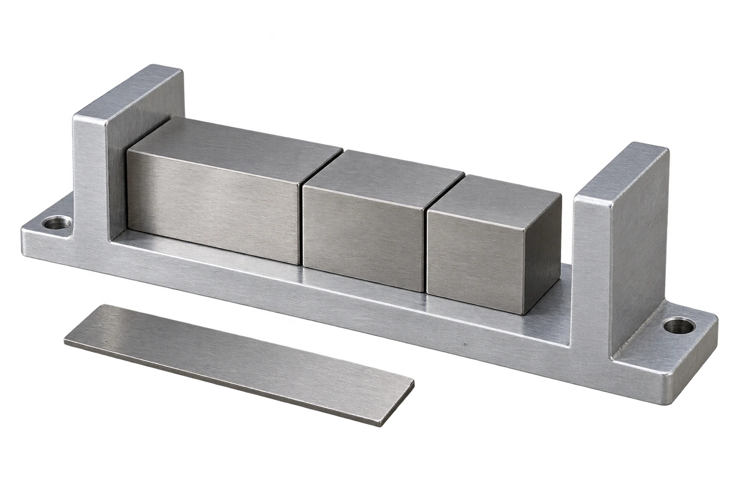
ASSEMBLY TOLERANCE ENGINEERING
치수의 연결.
조립의 완성.
공차 누적·기준면·간극과 양산 검증
Locate.
Stack.
Fit.
ASSEMBLY TOLERANCE ENGINEERING
맞닿는 면에서
기능을 읽습니다.
치수 사슬·공정 분포·환경·검사와 조정 조건을 함께 검토합니다.
DATUM · STACK · CLEARANCE · VALIDATION
Overview.
부품의 정밀도를 완성품의 기능으로 연결합니다.
정밀 부품은 각각의 도면을 만족하는 것에서 끝나지 않습니다. 여러 부품이 맞닿고 고정된 뒤에도 필요한 간극과 위치를 유지해야 완성품의 기능이 성립합니다. 공차 누적 설계는 그 연결 관계를 수치와 실제 접촉 상태로 설명하는 과정입니다.
이 글에서는 프레임과 스페이서 조립을 중심으로 치수 사슬, 최악조건, 통계 가정과 평균 이동을 비교합니다. 온도·표면처리·측정·심 조정을 함께 검토해 가공 가능한 공차가 안정적으로 조립되는 공차로 이어지도록 구성했습니다.
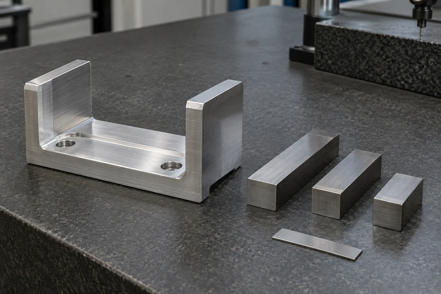
COMPONENT CHAIN / 분리된 부품과 조정용 심
Structure.
기능과 실제 접촉 경로
01 / FUNCTIONAL REQUIREMENT
부품 합격과 조립 합격 사이에 간극이 있습니다
공차 누적은 여러 치수가 최종 기능에 어떻게 도달하는지 설명하는 설계 도구입니다.
각 부품의 치수가 도면 안에 있어도 조립된 장치가 끼이거나 흔들릴 수 있습니다. 프레임 내부 길이, 스페이서 길이와 접촉 위치가 한 방향으로 겹치면 남는 간극은 개별 치수와 다른 범위를 갖습니다. 먼저 조립품에서 제어할 값이 간극인지, 돌출 높이인지, 축 정렬인지 명확하게 정해야 계산의 출발점이 만들어집니다.
간극이 너무 작으면 삽입과 이동을 방해하고, 너무 크면 위치 반복성이나 체결 후 자세가 달라질 수 있습니다. 이때 기능상 허용되는 하한과 상한은 제조하기 편한 수치에서 정하지 않습니다. 상대 부품, 하중, 온도와 필요한 움직임을 검토해 요구 범위를 정한 뒤 이를 부품 치수에 배분합니다.
아이디솔루텍의 조립 부품 검토에서는 도면의 치수 목록과 실제 맞닿는 면을 함께 읽는 접근이 중요합니다. 가공 가능 여부만 확인하면 조립 순서나 검사 기준에서 생기는 차이를 놓칠 수 있습니다. 설계·가공·측정 담당자가 동일한 기능 치수와 동일한 접촉 상태를 기준으로 판단하도록 검토 자료를 구성합니다.
기능값
간극·높이·정렬 등 최종 출력 · 측정 위치와 하중 상태를 지정
허용 범위
작동 가능한 상한과 하한 · 상대품·환경·움직임으로 결정
검토 경계
부품에서 완성 조립품까지 · 치수·접촉·조립 순서를 연결
부품 합격과 조립 합격 사이에 간극이 있습니다 — 실무 판단 기준
| 검토 항목 | 기술적 의미 | 검증·관리 기준 |
|---|---|---|
| 기능값 | 간극·높이·정렬 등 최종 출력 | 측정 위치와 하중 상태를 지정 |
| 허용 범위 | 작동 가능한 상한과 하한 | 상대품·환경·움직임으로 결정 |
| 검토 경계 | 부품에서 완성 조립품까지 | 치수·접촉·조립 순서를 연결 |
기능값
기술적 의미
간극·높이·정렬 등 최종 출력
검증·관리 기준
측정 위치와 하중 상태를 지정
허용 범위
기술적 의미
작동 가능한 상한과 하한
검증·관리 기준
상대품·환경·움직임으로 결정
검토 경계
기술적 의미
부품에서 완성 조립품까지
검증·관리 기준
치수·접촉·조립 순서를 연결
02 / DATUM AND CONTACT
치수 사슬은 실제 접촉면에서 닫혀야 합니다
기준면과 구속 방향을 정한 뒤 부호가 있는 치수 경로를 작성합니다.
프레임의 왼쪽 내면에 세 스페이서를 순서대로 밀착시키고 오른쪽에 간극을 남기는 조립을 생각할 수 있습니다. 왼쪽 기준에서 오른쪽 내면까지의 길이에서 각 스페이서의 길이를 빼면 간극이 됩니다. 반대로 한 부품을 중앙에 정렬하거나 양쪽에서 탄성 지지하면 접촉 관계가 달라지므로 같은 식을 그대로 적용할 수 없습니다.
도면의 기준 체계는 부품을 어디에 놓고 어떤 방향의 이동과 회전을 제한하는지와 연결됩니다. 크기 치수만 맞고 접촉면의 직각도나 평행도가 달라지면 한쪽 모서리만 닿을 수 있습니다. 넓은 면이 완전히 밀착한다는 가정이 필요한 계산이라면 면 형상과 자세도 함께 관리해야 합니다.
조립 지그의 기준과 제품 도면의 기준이 다르면 그 사이의 전달 치수가 추가됩니다. 검사 과정에서 다른 면을 잡아 얻은 값도 기능 치수와 자동으로 일치하지 않습니다. 도면 기준, 가공 기준, 조립 기준, 검사 기준을 나란히 표시하면 불필요한 기준 전환과 누락된 변수를 찾기 쉽습니다.
접촉 경로
실제로 맞닿는 면의 연결 · 조립 순서와 밀착 방향 표시
구속 조건
이동·회전의 제한 · 과구속·부유 부품 여부 확인
기준 전환
가공·조립·검사 간 관계 · 추가 치수와 오차를 포함
기준면과 구속 방향을 정한 뒤 부호가 있는 치수 경로를 작성합니다.
접촉 경로
실제로 맞닿는 면의 연결 · 조립 순서와 밀착 방향 표시
치수 사슬은 실제 접촉면에서 닫혀야 합니다 — 실무 판단 기준
| 검토 항목 | 기술적 의미 | 검증·관리 기준 |
|---|---|---|
| 접촉 경로 | 실제로 맞닿는 면의 연결 | 조립 순서와 밀착 방향 표시 |
| 구속 조건 | 이동·회전의 제한 | 과구속·부유 부품 여부 확인 |
| 기준 전환 | 가공·조립·검사 간 관계 | 추가 치수와 오차를 포함 |
접촉 경로
기술적 의미
실제로 맞닿는 면의 연결
검증·관리 기준
조립 순서와 밀착 방향 표시
구속 조건
기술적 의미
이동·회전의 제한
검증·관리 기준
과구속·부유 부품 여부 확인
기준 전환
기술적 의미
가공·조립·검사 간 관계
검증·관리 기준
추가 치수와 오차를 포함
Materials.
부호와 한계 조합
03 / SIGNED DIMENSION CHAIN
공차를 더하기 전에 치수의 방향을 정합니다
증가하면 간극이 커지는 치수와 작아지는 치수를 구별합니다.
일차원 직렬 조립에서는 내부 길이 H와 세 부품 길이 A, B, C로 G = H − A − B − C를 쓸 수 있습니다. H가 증가하면 간극이 커지고, 스페이서가 길어지면 간극이 줄어듭니다. 명목값을 대입한 결과가 실제 조립 방향과 맞는지 확인한 다음 각 치수를 하나씩 증가시켜 부호를 검산합니다.
양방향 대칭 공차만 있는 경우에는 반폭을 이용한 계산이 간단하지만, 단측 공차나 기준 이동이 있으면 상한과 하한을 직접 사용해야 합니다. 기준값에 임의로 ± 기호를 붙이면 평균 위치와 최악 조합을 잘못 해석할 수 있습니다. 치수별 명목값, 최소값, 최대값과 기능값에 대한 부호를 한 표에 보존합니다.
치수 사슬에는 같은 물리적 길이를 두 번 포함하지 않아야 합니다. 전체 길이와 그 안의 부분 길이를 독립 변수처럼 동시에 더하면 실제로 존재하지 않는 변동을 만들 수 있습니다. 공통 가공 기준이나 같은 측정값에서 계산된 항목은 종속 관계까지 표시해 모델의 자유도를 확인합니다.
부호
기능값에 대한 증가·감소 방향 · 입력 하나씩 변화시켜 검산
치수 한계
대칭·단측·비대칭 공차 · 실제 상한·하한 보존
중복 항목
전체와 부분 치수의 종속성 · 독립 변수만 선택
부호
기능값에 대한 증가·감소 방향 · 입력 하나씩 변화시켜 검산
공차를 더하기 전에 치수의 방향을 정합니다 — 실무 판단 기준
| 검토 항목 | 기술적 의미 | 검증·관리 기준 |
|---|---|---|
| 부호 | 기능값에 대한 증가·감소 방향 | 입력 하나씩 변화시켜 검산 |
| 치수 한계 | 대칭·단측·비대칭 공차 | 실제 상한·하한 보존 |
| 중복 항목 | 전체와 부분 치수의 종속성 | 독립 변수만 선택 |
| 기준 상태 | 하중·온도·표면처리 단계 | 계산값의 적용 시점 명시 |
부호
기술적 의미
기능값에 대한 증가·감소 방향
검증·관리 기준
입력 하나씩 변화시켜 검산
치수 한계
기술적 의미
대칭·단측·비대칭 공차
검증·관리 기준
실제 상한·하한 보존
중복 항목
기술적 의미
전체와 부분 치수의 종속성
검증·관리 기준
독립 변수만 선택
기준 상태
기술적 의미
하중·온도·표면처리 단계
검증·관리 기준
계산값의 적용 시점 명시

CONTACT FACES / 밀착면·가장자리·심 두께
04 / WORST CASE LIMITS
최악조건은 허용된 조합의 경계를 보여줍니다
모든 한계 조합을 허용해야 하는 기능에서는 끝값부터 확인합니다.
선형 직렬 모델의 최소 간극은 프레임이 가장 짧고 스페이서들이 가장 길 때 발생합니다. 최대 간극은 그 반대 조합입니다. 이 계산은 공정이 정규분포인지 또는 평균이 중앙에 있는지 가정하지 않으며, 입력 한계와 접촉 모델이 유효한 범위에서 기능의 양 끝을 확인하는 데 적합합니다.
최악조건에서 요구 범위를 넘는다고 모든 양산품이 불량이라는 뜻은 아닙니다. 허용된 부품 조합 가운데 기능을 만족하지 못하는 경우가 존재한다는 의미입니다. 반대로 최악조건 계산이 통과해도 누락된 면 기울기, 이물질, 열변형이나 체결 변형이 있으면 완성품 기능은 별도로 확인해야 합니다.
최악조건 여유가 부족하면 모든 부품의 공차를 똑같이 줄이기 전에 치수 사슬을 짧게 만들 수 있는지 봅니다. 일체 가공, 공통 기준, 접촉면 변경 또는 조정 구조가 효과적일 수 있습니다. 다만 구조 변경은 강성·정비성·제조 순서에도 영향을 주므로 간극 계산과 함께 검토합니다.
모든 한계 조합을 허용해야 하는 기능에서는 끝값부터 확인합니다.
최악조건은 허용된 조합의 경계를 보여줍니다 — 실무 판단 기준
| 검토 항목 | 기술적 의미 | 검증·관리 기준 |
|---|---|---|
| 최소 간극 | H 최소·부품 길이 최대 | 간섭과 작동 하한 검토 |
| 최대 간극 | H 최대·부품 길이 최소 | 유격과 위치 상한 검토 |
| 모델 범위 | 입력 한계와 접촉 가정 | 누락 변형을 별도 검증 |
| 개선 순서 | 사슬 단축·기준 통합·공차 조정 | 비용과 기능을 함께 비교 |
최소 간극
기술적 의미
H 최소·부품 길이 최대
검증·관리 기준
간섭과 작동 하한 검토
최대 간극
기술적 의미
H 최대·부품 길이 최소
검증·관리 기준
유격과 위치 상한 검토
모델 범위
기술적 의미
입력 한계와 접촉 가정
검증·관리 기준
누락 변형을 별도 검증
개선 순서
기술적 의미
사슬 단축·기준 통합·공차 조정
검증·관리 기준
비용과 기능을 함께 비교
3D · 기준면에서 기능 간극까지
STRUCTURE & INTERFACEID SOLUTECH / 01
작은 간극
인터랙티브 3D를 준비하고 있습니다.
부품 길이 합이 증가하면 오른쪽 간극이 줄어듭니다. 수치 예시의 실제 공차 비율을 표시한 것은 아닙니다.
드래그·방향키: 회전 / + −: 확대·축소 / Home: 초기화기준면에서 기능 간극까지
도면 안의 부품이 항상 기능 안의 조립품을 만드는 것은 아닙니다.
Precision.
공정 분포와 공통 원인
05 / PROCESS DISTRIBUTION
RSS는 도면 공차를 확률로 바꾸는 마법이 아닙니다
도면의 허용 한계와 공정의 표준편차는 다른 정보입니다.
독립적인 입력 변동을 선형으로 합성할 때 출력 분산은 각 민감도와 입력 분산으로 계산할 수 있습니다. 그러나 도면에 ±0.04 mm가 적혀 있다는 사실만으로 해당 공정의 3σ가 0.04 mm라고 정할 수는 없습니다. 실제 측정 분포, 공정 안정성, 선별 여부와 평균 위치가 뒷받침되어야 확률 해석이 가능합니다.
절삭 공구의 마모, 열 안정화, 설비 교대와 보정 주기 때문에 한 공정에서도 시간에 따라 분포가 바뀔 수 있습니다. 여러 로트를 한데 섞은 히스토그램은 로트별 평균 이동을 감출 수 있으므로 시간 순서와 설비 정보를 보존합니다. 안정된 단기 산포와 장기 생산 변동은 목적에 맞게 나누어 해석합니다.
부품을 치수별로 선별하거나 특정 공급 로트를 짝지으면 조립에 투입되는 분포가 입고 전체 분포와 달라집니다. 따라서 통계 계산은 실제 조립 흐름을 반영해야 합니다. 통계적 예측 범위가 요구 범위 안에 들어와도 꼬리 위험이 사라지는 것은 아니며, 허용 위험과 검증 방식은 제품 기능에 맞게 결정합니다.
입력 산포
실측 표준편차와 분포 · 도면 반폭을 자동으로 3σ로 바꾸지 않음
평균 위치
보정·마모·로트 이동 · 시간 순서로 확인
투입 모집단
선별·짝맞춤 이후의 부품 · 실제 조립 흐름 반영
입력 산포
실측 표준편차와 분포 · 도면 반폭을 자동으로 3σ로 바꾸지 않음
RSS는 도면 공차를 확률로 바꾸는 마법이 아닙니다 — 실무 판단 기준
| 검토 항목 | 기술적 의미 | 검증·관리 기준 |
|---|---|---|
| 입력 산포 | 실측 표준편차와 분포 | 도면 반폭을 자동으로 3σ로 바꾸지 않음 |
| 평균 위치 | 보정·마모·로트 이동 | 시간 순서로 확인 |
| 투입 모집단 | 선별·짝맞춤 이후의 부품 | 실제 조립 흐름 반영 |
| 예측 범위 | 정해진 가정 아래의 확률 구간 | 허용 위험과 검증을 명시 |
입력 산포
기술적 의미
실측 표준편차와 분포
검증·관리 기준
도면 반폭을 자동으로 3σ로 바꾸지 않음
평균 위치
기술적 의미
보정·마모·로트 이동
검증·관리 기준
시간 순서로 확인
투입 모집단
기술적 의미
선별·짝맞춤 이후의 부품
검증·관리 기준
실제 조립 흐름 반영
예측 범위
기술적 의미
정해진 가정 아래의 확률 구간
검증·관리 기준
허용 위험과 검증을 명시
06 / CORRELATION AND SENSITIVITY
공통 원인이 있으면 오차가 함께 움직입니다
같은 설비·온도·기준에서 만들어진 치수를 무조건 독립으로 취급하지 않습니다.
같은 공구 보정으로 두 스페이서 길이가 함께 증가한다면 두 항의 오차는 간극을 같은 방향으로 줄입니다. 반대로 프레임과 부품 길이가 같은 원인으로 비슷하게 증가하면 일부 효과가 상쇄될 수 있습니다. 상관계수의 부호만 보지 말고 기능식에서 각 항의 민감도 부호까지 함께 읽어야 합니다.
선형 모델의 분산에는 개별 항뿐 아니라 두 입력의 공분산 항이 포함됩니다. 공통 온도, 공통 기준 또는 동일 측정 장비에서 생기는 관계를 무시하면 산포를 작게도 크게도 예측할 수 있습니다. 관련성을 뒷받침할 생산 데이터가 부족하면 독립 가정과 가능한 상관 시나리오를 나란히 비교합니다.
영향도가 큰 항을 찾을 때는 도면 공차의 숫자만 순서대로 정렬하지 않습니다. 기능에 대한 민감도, 실제 산포, 평균 이동과 개선 비용을 함께 봅니다. 작은 각도라도 긴 레버 거리 끝의 위치에는 큰 영향을 줄 수 있으므로, 위치·각도 문제에서는 일차원 길이 사슬을 공간 모델로 확장합니다.
공통 원인
설비·공구·온도·기준 · 쌍을 이룬 생산 데이터 확인
민감도 부호
변화가 기능에 미치는 방향 · 상관 효과의 증폭·상쇄 구별
공분산
입력 간 함께 움직이는 정도 · 독립 합성과 비교
공통 원인
설비·공구·온도·기준 · 쌍을 이룬 생산 데이터 확인
공통 원인이 있으면 오차가 함께 움직입니다 — 실무 판단 기준
| 검토 항목 | 기술적 의미 | 검증·관리 기준 |
|---|---|---|
| 공통 원인 | 설비·공구·온도·기준 | 쌍을 이룬 생산 데이터 확인 |
| 민감도 부호 | 변화가 기능에 미치는 방향 | 상관 효과의 증폭·상쇄 구별 |
| 공분산 | 입력 간 함께 움직이는 정도 | 독립 합성과 비교 |
| 공간 영향 | 각도와 거리의 결합 | 회전·접촉 위치를 포함 |
공통 원인
기술적 의미
설비·공구·온도·기준
검증·관리 기준
쌍을 이룬 생산 데이터 확인
민감도 부호
기술적 의미
변화가 기능에 미치는 방향
검증·관리 기준
상관 효과의 증폭·상쇄 구별
공분산
기술적 의미
입력 간 함께 움직이는 정도
검증·관리 기준
독립 합성과 비교
공간 영향
기술적 의미
각도와 거리의 결합
검증·관리 기준
회전·접촉 위치를 포함
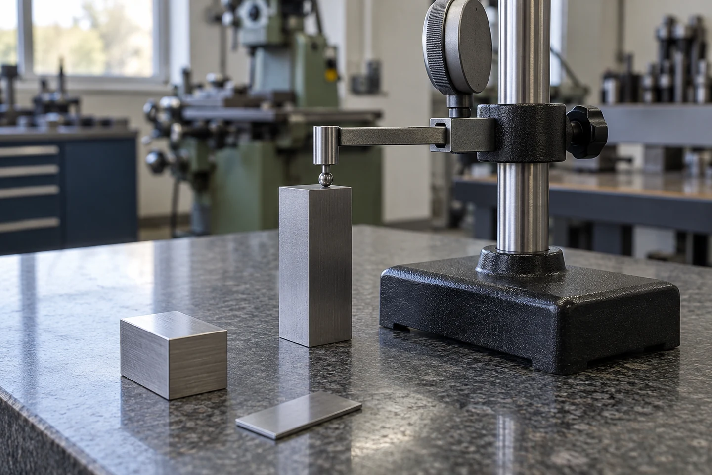
DIMENSIONAL INSPECTION / 기준면과 접촉 측정
Motion.
접촉 모델과 계산 가정
07 / CONTACT AND NONLINEARITY
면이 바뀌어 닿으면 계산식도 바뀝니다
기울기·체결·변형이 개입하는 조립은 접촉 상태를 먼저 검증합니다.
평면 두 개가 약간 기울어져 있으면 처음에는 가장자리에서 접촉하고, 체결력이 커지면서 접촉 영역과 자세가 달라질 수 있습니다. 이런 상태에서 한 치수의 변화가 간극에 미치는 영향은 일정한 계수 하나로 설명되지 않을 수 있습니다. 실제 구속과 접촉 순서를 확인해 강체 근사로 충분한 구간과 변형 해석이 필요한 구간을 나눕니다.
볼트 구멍의 여유를 이용해 위치를 조정하는 조립에서는 구멍 중심만으로 완성 위치가 결정되지 않습니다. 조립자가 어느 방향으로 밀어 고정하는지, 핀이나 별도 기준이 있는지, 체결 중 미끄럼이 발생하는지가 중요합니다. 위치 결정 기능과 체결 기능을 구분하면 계산과 작업 기준을 더 명확하게 만들 수 있습니다.
몬테카를로 계산은 입력 조합을 반복해 복잡한 출력 분포를 살펴보는 방법입니다. 반복 횟수를 늘리는 것만으로 잘못된 접촉 모델이나 입력 분포가 정확해지지는 않습니다. 비선형 구간, 상관관계, 평균 이동과 드문 불리한 조합을 포함하고, 계산의 수렴 및 실제 조립 결과와의 일치를 확인해야 합니다.
면 접촉
기울기·형상·국부 접촉 · 실제 지지 면을 확인
체결 경계
하중·순서·미끄럼 · 위치 결정과 체결 역할 구분
해석 수준
강체·접촉·탄성 모델 · 변형 크기와 기능 민감도로 선택
기울기·체결·변형이 개입하는 조립은 접촉 상태를 먼저 검증합니다.
면 접촉
기울기·형상·국부 접촉 · 실제 지지 면을 확인
면이 바뀌어 닿으면 계산식도 바뀝니다 — 실무 판단 기준
| 검토 항목 | 기술적 의미 | 검증·관리 기준 |
|---|---|---|
| 면 접촉 | 기울기·형상·국부 접촉 | 실제 지지 면을 확인 |
| 체결 경계 | 하중·순서·미끄럼 | 위치 결정과 체결 역할 구분 |
| 해석 수준 | 강체·접촉·탄성 모델 | 변형 크기와 기능 민감도로 선택 |
| 샘플링 | 입력 분포와 종속성 | 수렴·극단 조합·실물 비교 |
면 접촉
기술적 의미
기울기·형상·국부 접촉
검증·관리 기준
실제 지지 면을 확인
체결 경계
기술적 의미
하중·순서·미끄럼
검증·관리 기준
위치 결정과 체결 역할 구분
해석 수준
기술적 의미
강체·접촉·탄성 모델
검증·관리 기준
변형 크기와 기능 민감도로 선택
샘플링
기술적 의미
입력 분포와 종속성
검증·관리 기준
수렴·극단 조합·실물 비교
3D · 간극 확인과 심 조정
PROCESS & VALIDATIONID SOLUTECH / 02
밀착 상태
인터랙티브 3D를 준비하고 있습니다.
심이 기준벽과 첫 스페이서 사이에 밀착되면 전체 스택 길이가 늘어나 오른쪽 간극이 줄어듭니다.
드래그·방향키: 회전 / + −: 확대·축소 / Home: 초기화간극 확인과 심 조정
08 / NUMERICAL WINDOW
같은 치수 사슬도 계산 가정에 따라 판단이 달라집니다
가상의 프레임과 세 스페이서로 최악조건과 조건부 통계 범위를 비교합니다.
예시에서 H = 80.00±0.05 mm, A = 24.00±0.04 mm, B = 36.00±0.03 mm, C = 19.80±0.02 mm로 두면 명목 간극은 0.20 mm입니다. 요구 범위를 0.10–0.30 mm라고 가정하면 최악조건 반폭은 0.14 mm이며 간극은 0.06–0.34 mm가 됩니다. 따라서 허용된 모든 조합을 그대로 조립하는 조건에서는 양쪽 기능 한계를 넘을 수 있습니다.
별도의 가정으로 네 입력이 서로 독립이고 중앙에 맞춰진 정규분포이며 각 공차 반폭이 각각 3σ라고 두면 출력의 3σ는 약 0.0735 mm입니다. 이 조건부 범위는 약 0.1265–0.2735 mm입니다. 이는 실제 생산 데이터로 입증된 수율이나 모든 조합의 보증값이 아니며, 앞서 정한 분포 가정의 영향을 보여주는 계산입니다.
같은 산포를 유지해도 간극 평균이 +0.04 mm 이동하면 조건부 상단은 약 0.3135 mm로 올라갑니다. 단순 RSS 값만 보고 승인하면 이러한 평균 이동을 놓칠 수 있습니다. 여기의 수치는 계산 비교를 위한 가정이며, 3D의 간극 표시는 구조와 변화 방향을 읽기 쉽게 확대한 것으로 실제 치수나 공차 비율을 나타내지 않습니다.
G = H − A − B − C · TWC = TH + TA + TB + TC · σG² = Σ(ci²σi²) + 2Σpairs(ci cj Covij)
G: 조립 간극, H: 프레임 내부 길이, A·B·C: 스페이서 길이, T: 대칭 공차 반폭, ci: 기능 민감도, σi: 입력 표준편차. 최악조건과 통계식은 서로 다른 질문에 답하며, 두 번째 합은 중복 없는 입력쌍에 적용하며, 독립인 경우 공분산 항이 사라집니다.
명목 간극
80.00 − 24.00 − 36.00 − 19.80 · 0.20 mm
같은 치수 사슬도 계산 가정에 따라 판단이 달라집니다 — 실무 판단 기준
| 검토 항목 | 기술적 의미 | 검증·관리 기준 |
|---|---|---|
| 명목 간극 | 80.00 − 24.00 − 36.00 − 19.80 | 0.20 mm |
| 최악조건 | 반폭 0.05+0.04+0.03+0.02 | 0.06–0.34 mm |
| 조건부 RSS | 독립·중앙·각 반폭 = 3σ 가정 | 약 0.1265–0.2735 mm |
| 평균 이동 | 간극 평균 +0.04 mm 가정 | 조건부 상단 약 0.3135 mm |
명목 간극
기술적 의미
80.00 − 24.00 − 36.00 − 19.80
검증·관리 기준
0.20 mm
최악조건
기술적 의미
반폭 0.05+0.04+0.03+0.02
검증·관리 기준
0.06–0.34 mm
조건부 RSS
기술적 의미
독립·중앙·각 반폭 = 3σ 가정
검증·관리 기준
약 0.1265–0.2735 mm
평균 이동
기술적 의미
간극 평균 +0.04 mm 가정
검증·관리 기준
조건부 상단 약 0.3135 mm
통계 계산의 신뢰도는 입력 가정과 생산 데이터에서 시작됩니다.
Interface.
사용 상태와 검사 기준
09 / TEMPERATURE AND FINISH
조립 후의 온도와 표면층도 간극을 바꿉니다
기준 온도에서의 치수와 사용 상태의 기능을 연결합니다.
서로 다른 열팽창 특성을 가진 프레임과 스페이서를 조립하면 온도 변화에 따라 간극이 달라집니다. 균일한 온도 변화와 일정한 평균 팽창계수를 가정한 일차 근사에서는 각 길이에 팽창량을 계산한 뒤 기존 치수 사슬의 부호로 합성할 수 있습니다. 온도 구배나 구속 응력이 크면 이 단순 계산의 범위를 벗어납니다.
가정값으로 프레임 계수 23×10⁻⁶/K, 스페이서 계수 12×10⁻⁶/K, 길이 80.0 mm와 합계 79.8 mm, 온도 상승 40 K를 적용하면 간극 증가는 약 0.0353 mm입니다. 이는 특정 합금의 보증 물성이나 실제 장치의 예측값이 아닙니다. 선정 소재의 온도별 자료와 실제 부품 온도를 확보해 같은 방법으로 다시 계산해야 합니다.
도금이나 코팅은 어느 면에 형성되는지에 따라 유효 길이를 바꿉니다. 내부 맞춤면과 양쪽 끝면을 같은 두께 항 하나로 처리하지 말고 접촉에 관여하는 면별로 치수 영향을 작성합니다. 도면이 처리 전 치수인지 최종 치수인지 명시하고, 마스킹·연삭·세척을 거친 완성 상태로 검사 경계를 맞춥니다.
기준 온도에서의 치수와 사용 상태의 기능을 연결합니다.
열팽창
길이·계수·온도 변화 · 부품별 온도와 구속 조건 확인
조립 후의 온도와 표면층도 간극을 바꿉니다 — 실무 판단 기준
| 검토 항목 | 기술적 의미 | 검증·관리 기준 |
|---|---|---|
| 열팽창 | 길이·계수·온도 변화 | 부품별 온도와 구속 조건 확인 |
| 기준 상태 | 측정 온도와 사용 온도 | 치수 보정과 기능 변화를 구분 |
| 표면층 | 접촉면별 유효 치수 변화 | 내면·외면·양 끝면을 구별 |
| 최종 검사 | 처리·연삭·세척 이후 상태 | 도면의 적용 시점과 일치 |
열팽창
기술적 의미
길이·계수·온도 변화
검증·관리 기준
부품별 온도와 구속 조건 확인
기준 상태
기술적 의미
측정 온도와 사용 온도
검증·관리 기준
치수 보정과 기능 변화를 구분
표면층
기술적 의미
접촉면별 유효 치수 변화
검증·관리 기준
내면·외면·양 끝면을 구별
최종 검사
기술적 의미
처리·연삭·세척 이후 상태
검증·관리 기준
도면의 적용 시점과 일치
10 / MEASUREMENT AND DECISION
측정값의 작은 차이를 모두 가공 오차로 보지 않습니다
측정 불확도와 공정 산포를 나눠 관리해야 개선 방향이 정확해집니다.
스페이서 길이를 비교 측정할 때는 바닥 기준면의 청결, 접촉력, 측정 위치와 부품 온도가 결과에 영향을 줄 수 있습니다. 같은 부품을 다시 놓았을 때의 변화와 다른 부품 사이의 차이를 구별해야 합니다. 측정 반복성과 작업자·설치 변경 영향을 확인한 뒤 생산 분포를 해석합니다.
부품별 치수를 합산한 간극 예측과 완성 조립품에서 직접 측정한 간극은 서로를 검증하는 데 유용합니다. 두 결과가 맞지 않으면 누락된 표면층, 밀착 불량, 면 기울기 또는 체결 변형을 살펴봅니다. 직접 측정에도 측정력과 접근 방향이 있으므로 제품의 사용 상태와 다른 방법으로 틈을 벌리지 않도록 합니다.
측정 결과가 규격 경계에 가까울수록 측정 불확도와 합격 판정 규칙을 함께 고려해야 합니다. 장비 표시 분해능만으로 판정의 신뢰성을 결정하지 않습니다. 고객과 합의한 판정 방식, 기준기와 교정 상태, 온도 안정화 및 재측정 절차를 검사 기록에 연결하면 경계값에 대한 반복 논쟁을 줄일 수 있습니다.
반복 측정
같은 부품의 재배치 영향 · 공정 산포와 구별
측정 경계
기준·접촉력·온도·위치 · 작업 방법을 고정
조립 대조
부품 합산과 직접 간극 · 누락 접촉·변형을 확인
반복 측정
같은 부품의 재배치 영향 · 공정 산포와 구별
측정값의 작은 차이를 모두 가공 오차로 보지 않습니다 — 실무 판단 기준
| 검토 항목 | 기술적 의미 | 검증·관리 기준 |
|---|---|---|
| 반복 측정 | 같은 부품의 재배치 영향 | 공정 산포와 구별 |
| 측정 경계 | 기준·접촉력·온도·위치 | 작업 방법을 고정 |
| 조립 대조 | 부품 합산과 직접 간극 | 누락 접촉·변형을 확인 |
| 판정 규칙 | 불확도와 규격 경계의 관계 | 합의된 합격 조건을 기록 |
반복 측정
기술적 의미
같은 부품의 재배치 영향
검증·관리 기준
공정 산포와 구별
측정 경계
기술적 의미
기준·접촉력·온도·위치
검증·관리 기준
작업 방법을 고정
조립 대조
기술적 의미
부품 합산과 직접 간극
검증·관리 기준
누락 접촉·변형을 확인
판정 규칙
기술적 의미
불확도와 규격 경계의 관계
검증·관리 기준
합의된 합격 조건을 기록
Validation.
조정과 양산 검증
11 / ADJUSTMENT STRATEGY
심 조정과 선택 조립은 추적 가능한 공정이어야 합니다
조정으로 얻는 여유를 재작업·재고·서비스 조건까지 연결합니다.
직렬 스페이서 조립에서 심을 추가하면 스택 길이가 늘어나 간극이 줄어듭니다. 예를 들어 측정된 초기 간극 0.28 mm에 0.10 mm 심을 넣으면 단순 강체 계산상 0.18 mm가 됩니다. 이미 간섭하는 조립에 심을 더하는 방식은 문제를 악화시키므로 조정 방향과 허용 범위를 작업표에 명확하게 표시합니다.
심의 두께 공차, 평탄도, 이물질과 체결 후 밀착 상태도 최종 결과에 포함됩니다. 여러 장을 겹치면 접촉면 수와 관리 항목이 늘어날 수 있으므로 허용 조합과 최대 적층 조건을 정합니다. 두 번째 3D는 간극 확인, 심 투입, 밀착, 최종 확인의 순서를 보여주며 조정 전후 같은 기준으로 검사하는 이유를 설명합니다.
선택 조립은 치수를 측정해 정해진 구간으로 분류한 뒤 적합한 조합을 만드는 방법입니다. 한 구간의 부품만 부족해지는 재고 불균형, 측정 비용, 잘못된 혼입과 교체 부품의 호환성을 함께 검토해야 합니다. 조정 없이 호환되어야 하는 제품과 기록된 조합으로 관리할 수 있는 제품은 같은 전략을 적용하지 않습니다.
조정 방향
심 추가 시 간극 감소 · 초기 간섭과 과대 간극을 구별
심 관리
두께·평탄도·적층 조건 · 부품 번호와 최종 조합 기록
선택 조립
측정 구간별 짝맞춤 · 재고 균형·혼입·비용 검토
조정으로 얻는 여유를 재작업·재고·서비스 조건까지 연결합니다.
조정 방향
심 추가 시 간극 감소 · 초기 간섭과 과대 간극을 구별
심 조정과 선택 조립은 추적 가능한 공정이어야 합니다 — 실무 판단 기준
| 검토 항목 | 기술적 의미 | 검증·관리 기준 |
|---|---|---|
| 조정 방향 | 심 추가 시 간극 감소 | 초기 간섭과 과대 간극을 구별 |
| 심 관리 | 두께·평탄도·적층 조건 | 부품 번호와 최종 조합 기록 |
| 선택 조립 | 측정 구간별 짝맞춤 | 재고 균형·혼입·비용 검토 |
| 서비스 | 재조립과 교체 부품 | 호환성 또는 조합 추적을 정의 |
조정 방향
기술적 의미
심 추가 시 간극 감소
검증·관리 기준
초기 간섭과 과대 간극을 구별
심 관리
기술적 의미
두께·평탄도·적층 조건
검증·관리 기준
부품 번호와 최종 조합 기록
선택 조립
기술적 의미
측정 구간별 짝맞춤
검증·관리 기준
재고 균형·혼입·비용 검토
서비스
기술적 의미
재조립과 교체 부품
검증·관리 기준
호환성 또는 조합 추적을 정의
12 / PRODUCTION VALIDATION
공차 계산은 양산 데이터로 닫아야 합니다
계산·가공·검사·조립을 같은 기능값으로 연결하면 개선 우선순위가 분명해집니다.
개발 단계에서는 명목 조립만 성공시키기보다 불리한 치수 조합과 사용 조건을 의도적으로 확인합니다. 최소·최대 간극 부근에서 삽입성, 움직임, 체결 후 위치와 필요한 하중 기능을 검증합니다. 이 결과를 계산 모델과 대조하면 누락한 접촉이나 변형을 찾고 다음 설계 변경의 근거를 만들 수 있습니다.
양산 관리에는 부품 치수뿐 아니라 완성 간극의 시간 추이, 설비·공구·로트와 조정 이력을 함께 남깁니다. 평균이 이동할 때 산포를 줄이는 조치만 반복하거나, 측정 방식이 바뀐 결과를 공정 개선으로 해석하지 않아야 합니다. 변경 전후 같은 기준으로 비교하고 승인된 입력 범위를 벗어나면 모델과 검사 계획을 다시 검토합니다.
결론적으로 좋은 공차 설계는 모든 치수를 가장 작게 제한하는 일이 아닙니다. 기능을 결정하는 접촉 경로를 정확히 모델링하고, 한계 조합과 통계 가정을 구분하며, 제조와 검사에서 유지할 수 있는 여유를 배분하는 일입니다. 도면·조립 순서·온도·표면처리·검사 조건을 함께 준비하면 정밀 부품의 가공성과 조립 신뢰성을 더 일관되게 검토할 수 있습니다.
개발 확인
불리한 조합과 환경 · 기능 상·하한 부근을 시험
양산 데이터
치수·간극·시간·설비 · 평균 이동과 산포를 분리
변경 관리
공구·재료·처리·측정 방법 · 모델과 검사 계획 재검토
개발 확인
불리한 조합과 환경 · 기능 상·하한 부근을 시험
공차 계산은 양산 데이터로 닫아야 합니다 — 실무 판단 기준
| 검토 항목 | 기술적 의미 | 검증·관리 기준 |
|---|---|---|
| 개발 확인 | 불리한 조합과 환경 | 기능 상·하한 부근을 시험 |
| 양산 데이터 | 치수·간극·시간·설비 | 평균 이동과 산포를 분리 |
| 변경 관리 | 공구·재료·처리·측정 방법 | 모델과 검사 계획 재검토 |
| 협의 자료 | 도면·접촉·하중·온도·기준 | 완성 기능에 맞춰 검토 |
개발 확인
기술적 의미
불리한 조합과 환경
검증·관리 기준
기능 상·하한 부근을 시험
양산 데이터
기술적 의미
치수·간극·시간·설비
검증·관리 기준
평균 이동과 산포를 분리
변경 관리
기술적 의미
공구·재료·처리·측정 방법
검증·관리 기준
모델과 검사 계획 재검토
협의 자료
기술적 의미
도면·접촉·하중·온도·기준
검증·관리 기준
완성 기능에 맞춰 검토
공차의 목적은 가장 작은 숫자가 아니라 유지되는 기능입니다.
개발 상담 · Contact
연락처 · Get in Touch
기술 협의 · Engineering Consultation
도면과 사양을 기준으로 소재·가공·표면처리,
주요 품질 항목과 공급 조건을 함께 검토합니다.
We review drawings and specifications to define materials, manufacturing methods, surface finishes, key quality requirements, and supply conditions.
주요 품질 항목과 공급 조건을 함께 검토합니다.
We review drawings and specifications to define materials, manufacturing methods, surface finishes, key quality requirements, and supply conditions.
개발 의뢰하기 · Development Inquiry
ASSEMBLY TOLERANCE ENGINEERING
Read Function
at the Contact.
Review dimension chains, process populations, environment, measurement and adjustment together.
DATUM · STACK · CLEARANCE · VALIDATION
ENGLISH EDITION
Connected Dimensions.
Completed Function.
Tolerance stacks, datums, clearance and production validation
Connect component precision to finished-assembly function.
Precision components must do more than meet their individual drawings. Once parts are seated and secured, the assembly must preserve the clearance and position required for its function. Tolerance analysis connects these requirements through dimensions and actual contact conditions.
Using a frame and spacer stack, this article compares signed dimension chains, worst-case limits, statistical assumptions and mean shifts. Temperature, finishing, measurement and shimming complete the link between manufacturable components and consistent assembly performance.
COMPONENT CHAIN / Separate parts and adjustment shim
Structure.
Function and actual contact paths
01 / FUNCTIONAL REQUIREMENT
Part Conformance and Assembly Function Are Different Checks
Tolerance analysis follows multiple dimensions to the final functional requirement.
Every component can meet its drawing while the assembled mechanism binds or moves excessively. Frame opening, spacer lengths and contact positions combine to produce a clearance range different from any individual dimension. Begin by defining the assembly output: a gap, a protrusion, an alignment or another functional quantity.
Insufficient clearance can obstruct insertion or movement; excessive clearance can change repeatability or the final clamped attitude. Functional limits should therefore come from mating parts, loads, temperature and required motion. Allocate dimensions only after the acceptable assembly window is established.
A useful review of precision assembly components connects the dimension list with the surfaces that actually touch. Machinability alone does not resolve differences introduced by assembly sequence or inspection setup. Organize the review so design, manufacturing and measurement use the same functional dimension and contact state.
Functional output
Gap, height, alignment or another result. Specify measurement location and load
Acceptance window
Upper and lower functional limits. Derive from mating parts and service conditions
Review boundary
From components to the finished assembly. Connect dimensions, contact and sequence
Part Conformance and Assembly Function Are Different Checks — Review Criteria
| Review item | Engineering significance | Verification or control |
|---|---|---|
| Functional output | Gap, height, alignment or another result | Specify measurement location and load |
| Acceptance window | Upper and lower functional limits | Derive from mating parts and service conditions |
| Review boundary | From components to the finished assembly | Connect dimensions, contact and sequence |
Functional output
Engineering significance
Gap, height, alignment or another result
Verification or control
Specify measurement location and load
Acceptance window
Engineering significance
Upper and lower functional limits
Verification or control
Derive from mating parts and service conditions
Review boundary
Engineering significance
From components to the finished assembly
Verification or control
Connect dimensions, contact and sequence
02 / DATUM AND CONTACT
Close the Dimensional Loop Through the Actual Contacts
Define datums and restraint directions before writing a signed dimensional chain.
Consider three spacers seated against the left internal wall of a frame, leaving a gap at the right. Subtracting their lengths from the internal opening gives the clearance. A centered component or an assembly supported elastically from both sides has a different contact relationship and needs a different model.
A datum scheme determines placement and the translations or rotations being restrained. Correct size does not prevent edge contact when mating surfaces have orientation or form deviations. If the calculation assumes full planar seating, surface form and orientation must be controlled consistently with that assumption.
A fixture that locates from a different surface adds a transfer relationship to the product datum scheme. A measurement taken from another surface is likewise not automatically the functional dimension. Compare design, machining, assembly and inspection datums to expose unnecessary transfers and missing variables.
Contact path
Sequence of surfaces that actually touch. Show seating direction and assembly order
Restraint
Constrained translations and rotations. Check overconstraint and floating parts
Datum transfer
Relationship between process setups. Include added dimensions and variation
Define datums and restraint directions before writing a signed dimensional chain.
Contact path
Sequence of surfaces that actually touch. Show seating direction and assembly order
Close the Dimensional Loop Through the Actual Contacts — Review Criteria
| Review item | Engineering significance | Verification or control |
|---|---|---|
| Contact path | Sequence of surfaces that actually touch | Show seating direction and assembly order |
| Restraint | Constrained translations and rotations | Check overconstraint and floating parts |
| Datum transfer | Relationship between process setups | Include added dimensions and variation |
Contact path
Engineering significance
Sequence of surfaces that actually touch
Verification or control
Show seating direction and assembly order
Restraint
Engineering significance
Constrained translations and rotations
Verification or control
Check overconstraint and floating parts
Datum transfer
Engineering significance
Relationship between process setups
Verification or control
Include added dimensions and variation
Materials.
Signs and dimensional extremes
03 / SIGNED DIMENSION CHAIN
Assign the Sign Before Combining Tolerances
Separate dimensions that increase clearance from those that reduce it.
For a one-dimensional series stack, write G = H − A − B − C, where H is the frame opening and A, B and C are component lengths. Increasing H opens the gap; increasing a spacer closes it. Check the nominal assembly, then perturb each input individually to confirm the sign.
Symmetric bilateral tolerances allow a convenient half-width calculation. Unilateral limits or shifted nominal values require the actual upper and lower bounds. Adding a convenient ± sign can misrepresent both centering and extreme combinations. Preserve nominal, minimum, maximum and functional sign for every input.
Avoid counting the same physical length twice. Treating an overall dimension and its component segments as independent inputs can create variation that the assembly cannot possess. Mark dependencies created by common machining references or derived measurements before choosing the model variables.
Sign
Direction of influence on the output. Perturb one input at a time
Dimension limits
Bilateral, unilateral or asymmetric. Retain actual upper and lower values
Duplicate terms
Dependence of overall and segment lengths. Select independent model variables
Sign
Direction of influence on the output. Perturb one input at a time
Assign the Sign Before Combining Tolerances — Review Criteria
| Review item | Engineering significance | Verification or control |
|---|---|---|
| Sign | Direction of influence on the output | Perturb one input at a time |
| Dimension limits | Bilateral, unilateral or asymmetric | Retain actual upper and lower values |
| Duplicate terms | Dependence of overall and segment lengths | Select independent model variables |
| Reference state | Load, temperature and finishing stage | State when the calculation applies |
Sign
Engineering significance
Direction of influence on the output
Verification or control
Perturb one input at a time
Dimension limits
Engineering significance
Bilateral, unilateral or asymmetric
Verification or control
Retain actual upper and lower values
Duplicate terms
Engineering significance
Dependence of overall and segment lengths
Verification or control
Select independent model variables
Reference state
Engineering significance
Load, temperature and finishing stage
Verification or control
State when the calculation applies
CONTACT FACES / Seating surfaces, edges and shim thickness
04 / WORST CASE LIMITS
Worst-Case Analysis Defines the Permitted Extremes
Check the extremes when every allowed dimensional combination must function.
In a linear series model, minimum clearance occurs with the shortest frame opening and longest spacers. Maximum clearance uses the opposite extremes. This calculation does not require normally distributed or centered processes; it evaluates the boundaries permitted by the input limits and contact model.
Failure of a worst-case check does not mean every production assembly will fail. It means that some allowed dimensional combinations do not meet the function. Passing the calculation also cannot account for omitted tilt, contamination, thermal change or fastening deformation; finished-assembly validation remains necessary.
When worst-case margin is inadequate, first consider shortening the chain rather than tightening every component equally. Integrated machining, shared datums, revised contacts or an adjustment feature may help. Each change also affects stiffness, serviceability and production sequence, so evaluate the assembly as a system.
Check the extremes when every allowed dimensional combination must function.
Worst-Case Analysis Defines the Permitted Extremes — Review Criteria
| Review item | Engineering significance | Verification or control |
|---|---|---|
| Minimum clearance | Minimum H and maximum component lengths | Check interference and lower functional limit |
| Maximum clearance | Maximum H and minimum component lengths | Check play and upper functional limit |
| Model boundary | Input limits and contact assumptions | Verify omitted deformation separately |
| Improvement order | Shorten chains, share datums, then allocate limits | Compare cost with functional benefit |
Minimum clearance
Engineering significance
Minimum H and maximum component lengths
Verification or control
Check interference and lower functional limit
Maximum clearance
Engineering significance
Maximum H and minimum component lengths
Verification or control
Check play and upper functional limit
Model boundary
Engineering significance
Input limits and contact assumptions
Verification or control
Verify omitted deformation separately
Improvement order
Engineering significance
Shorten chains, share datums, then allocate limits
Verification or control
Compare cost with functional benefit
3D · From Datum to Functional Clearance
STRUCTURE & INTERFACEID SOLUTECH / 01
Smaller clearance
Preparing interactive 3D.
A longer stack reduces clearance. Geometry does not reproduce the numerical example or actual tolerance ratios.
Drag / arrow keys: rotate · + −: zoom · Home: resetFrom Datum to Functional Clearance
Conforming components do not automatically create a functioning assembly.
Precision.
Process distributions and shared causes
05 / PROCESS DISTRIBUTION
RSS Requires a Defensible Process Model
Drawing limits and process standard deviations are different information.
For independent inputs in a linear model, output variance follows from the sensitivities and input variances. A drawing limit of ±0.04 mm does not establish that the process has a 3σ spread of 0.04 mm. Probability statements require evidence about measured distributions, stability, screening and centering.
Tool wear, warm-up, machine changes and offset cycles can alter the distribution over time. A pooled histogram may conceal shifts between lots. Preserve time order and machine identity, and distinguish short-term stable spread from longer-term production variation when selecting inputs.
Dimensional sorting or lot-specific pairing changes the population entering assembly. The statistical model must represent that actual flow. A predicted interval inside the specification does not eliminate tail risk; acceptable risk and validation must be chosen for the product function.
Input spread
Measured standard deviation and distribution. Do not automatically equate tolerance half-width with 3σ
Mean location
Offsets, wear and lot shifts. Inspect time-ordered data
Assembly population
Parts after sorting or matching. Represent the actual production flow
Input spread
Measured standard deviation and distribution. Do not automatically equate tolerance half-width with 3σ
RSS Requires a Defensible Process Model — Review Criteria
| Review item | Engineering significance | Verification or control |
|---|---|---|
| Input spread | Measured standard deviation and distribution | Do not automatically equate tolerance half-width with 3σ |
| Mean location | Offsets, wear and lot shifts | Inspect time-ordered data |
| Assembly population | Parts after sorting or matching | Represent the actual production flow |
| Prediction interval | Probability range under stated assumptions | Define acceptable risk and validation |
Input spread
Engineering significance
Measured standard deviation and distribution
Verification or control
Do not automatically equate tolerance half-width with 3σ
Mean location
Engineering significance
Offsets, wear and lot shifts
Verification or control
Inspect time-ordered data
Assembly population
Engineering significance
Parts after sorting or matching
Verification or control
Represent the actual production flow
Prediction interval
Engineering significance
Probability range under stated assumptions
Verification or control
Define acceptable risk and validation
06 / CORRELATION AND SENSITIVITY
Shared Causes Make Dimensions Move Together
Dimensions sharing a machine, temperature or datum may not be independent.
If one tool offset increases two spacer lengths together, both changes close the gap. If the frame opening and a spacer increase together, their effects may partly cancel. Interpret correlation together with the signs of the functional sensitivities, not from the correlation coefficient alone.
A linear variance model includes covariance terms as well as individual variances. Ignoring shared temperature, references or measurement effects can underpredict or overpredict spread. When production evidence is limited, compare the independent case with plausible dependence scenarios rather than asserting independence.
Prioritization should not simply rank the tolerance numbers on the drawing. Combine functional sensitivity, measured spread, mean shifts and improvement cost. A small angular error can create a substantial positional change over a long lever arm, requiring a spatial model rather than a length-only chain.
Shared cause
Machine, tool, temperature or datum. Examine paired production observations
Sensitivity sign
Direction of functional influence. Distinguish amplification from cancellation
Covariance
Joint movement of inputs. Compare against the independent model
Shared cause
Machine, tool, temperature or datum. Examine paired production observations
Shared Causes Make Dimensions Move Together — Review Criteria
| Review item | Engineering significance | Verification or control |
|---|---|---|
| Shared cause | Machine, tool, temperature or datum | Examine paired production observations |
| Sensitivity sign | Direction of functional influence | Distinguish amplification from cancellation |
| Covariance | Joint movement of inputs | Compare against the independent model |
| Spatial influence | Angle acting over a distance | Include rotation and contact location |
Shared cause
Engineering significance
Machine, tool, temperature or datum
Verification or control
Examine paired production observations
Sensitivity sign
Engineering significance
Direction of functional influence
Verification or control
Distinguish amplification from cancellation
Covariance
Engineering significance
Joint movement of inputs
Verification or control
Compare against the independent model
Spatial influence
Engineering significance
Angle acting over a distance
Verification or control
Include rotation and contact location
DIMENSIONAL INSPECTION / Datum and contact measurement
Motion.
Contact models and calculation assumptions
07 / CONTACT AND NONLINEARITY
A Change in Contact Can Change the Model
Validate the contact state when tilt, fastening or deformation enters the assembly.
Slightly tilted faces may first contact along an edge, then change contact area and attitude as fastening load increases. The influence of a dimensional change may no longer have one constant coefficient. Identify the actual restraint and sequence, separating regions suited to a rigid approximation from those needing deformation analysis.
An assembly positioned within bolt-hole clearance is not located by hole centers alone. Seating direction, locating pins, dedicated datums and slip during tightening determine the final position. Separating location from fastening clarifies both the analysis and the work instruction.
Monte Carlo evaluation samples input combinations to examine a complex output distribution. More trials cannot repair an incorrect contact model or input population. Include nonlinear behavior, dependence, mean shifts and relevant adverse combinations, then check numerical convergence and agreement with physical assemblies.
Surface contact
Tilt, form and local seating. Identify the actual support
Fastening boundary
Load, sequence and slip. Separate location from clamping
Model fidelity
Rigid, contact or elastic representation. Choose from deformation and functional sensitivity
Validate the contact state when tilt, fastening or deformation enters the assembly.
Surface contact
Tilt, form and local seating. Identify the actual support
A Change in Contact Can Change the Model — Review Criteria
| Review item | Engineering significance | Verification or control |
|---|---|---|
| Surface contact | Tilt, form and local seating | Identify the actual support |
| Fastening boundary | Load, sequence and slip | Separate location from clamping |
| Model fidelity | Rigid, contact or elastic representation | Choose from deformation and functional sensitivity |
| Sampling | Input distributions and dependence | Check convergence, extremes and physical results |
Surface contact
Engineering significance
Tilt, form and local seating
Verification or control
Identify the actual support
Fastening boundary
Engineering significance
Load, sequence and slip
Verification or control
Separate location from clamping
Model fidelity
Engineering significance
Rigid, contact or elastic representation
Verification or control
Choose from deformation and functional sensitivity
Sampling
Engineering significance
Input distributions and dependence
Verification or control
Check convergence, extremes and physical results
3D · Clearance Review and Shimming
PROCESS & VALIDATIONID SOLUTECH / 02
Seated adjustment
Preparing interactive 3D.
Seating the shim between the datum wall and first spacer increases stack length and reduces right-hand clearance.
Drag / arrow keys: rotate · + −: zoom · Home: resetClearance Review and Shimming
08 / NUMERICAL WINDOW
The Same Stack Gives Different Answers Under Different Assumptions
A hypothetical frame and three spacers illustrate worst-case and conditional statistical ranges.
Assume H = 80.00±0.05 mm, A = 24.00±0.04 mm, B = 36.00±0.03 mm and C = 19.80±0.02 mm. Nominal clearance is 0.20 mm. For a hypothetical requirement of 0.10–0.30 mm, the worst-case half-width is 0.14 mm, giving 0.06–0.34 mm. Some permitted combinations therefore exceed either functional limit.
In a separate scenario, assume independent centered normal inputs with each tolerance half-width equal to its own 3σ. The output 3σ is approximately 0.0735 mm, giving a conditional range of 0.1265–0.2735 mm. This is neither a measured production yield nor a guarantee for every combination; it illustrates the effect of the stated distribution assumptions.
With the same spread, a +0.04 mm shift in mean clearance raises the conditional upper end to approximately 0.3135 mm. Approval based only on an RSS width would miss that shift. These numbers are hypothetical; clearances in the 3D views are enlarged to show relationships and change directions, rather than reproduce the numeric dimensions or tolerance ratios.
G = H − A − B − C · TWC = TH + TA + TB + TC · σG² = Σ(ci²σi²) + 2Σpairs(ci cj Covij)
G: clearance; H: frame opening; A, B, C: spacer lengths; T: symmetric tolerance half-width; ci: functional sensitivity; σi: input standard deviation. Worst-case and statistical models answer different questions; the second sum covers unique input pairs, and independence removes the covariance terms.
Nominal clearance
80.00 − 24.00 − 36.00 − 19.80. 0.20 mm
The Same Stack Gives Different Answers Under Different Assumptions — Review Criteria
| Review item | Engineering significance | Verification or control |
|---|---|---|
| Nominal clearance | 80.00 − 24.00 − 36.00 − 19.80 | 0.20 mm |
| Worst case | Half-width 0.05+0.04+0.03+0.02 | 0.06–0.34 mm |
| Conditional RSS | Independent, centered inputs; each half-width = 3σ | Approximately 0.1265–0.2735 mm |
| Mean shift | Assumed +0.04 mm clearance shift | Conditional upper end approximately 0.3135 mm |
Nominal clearance
Engineering significance
80.00 − 24.00 − 36.00 − 19.80
Verification or control
0.20 mm
Worst case
Engineering significance
Half-width 0.05+0.04+0.03+0.02
Verification or control
0.06–0.34 mm
Conditional RSS
Engineering significance
Independent, centered inputs; each half-width = 3σ
Verification or control
Approximately 0.1265–0.2735 mm
Mean shift
Engineering significance
Assumed +0.04 mm clearance shift
Verification or control
Conditional upper end approximately 0.3135 mm
Statistical confidence starts with defensible inputs and production evidence.
Interface.
Service conditions and measurement boundaries
09 / TEMPERATURE AND FINISH
Temperature and Finishing Change the Final Clearance
Connect dimensions at the reference condition with function in service.
A frame and spacers with different thermal expansion behavior change clearance as temperature changes. Under uniform temperature change and approximately constant expansion coefficients, calculate each length change and combine it with the original chain signs. Large gradients or constrained thermal stresses require a more complete model.
For hypothetical coefficients of 23×10⁻⁶/K for the frame and 12×10⁻⁶/K for the spacers, lengths of 80.0 mm and 79.8 mm, and a 40 K rise, clearance increases by about 0.0353 mm. These are assumed inputs, not guaranteed alloy properties or a device prediction. Recalculate with the selected material data and actual component temperatures.
Plating or coating changes effective dimensions according to the surfaces receiving it. Do not represent an internal opening and two coated end faces by one undifferentiated thickness term. Track the participating surfaces, specify whether dimensions apply before or after finishing, and inspect the completed state after masking, grinding and cleaning.
Connect dimensions at the reference condition with function in service.
Thermal expansion
Length, coefficient and temperature change. Check component temperatures and restraints
Temperature and Finishing Change the Final Clearance — Review Criteria
| Review item | Engineering significance | Verification or control |
|---|---|---|
| Thermal expansion | Length, coefficient and temperature change | Check component temperatures and restraints |
| Reference state | Measurement and service temperatures | Separate correction from functional change |
| Surface layer | Effective dimensional change per contact face | Distinguish inner, outer and end surfaces |
| Final inspection | State after finishing, grinding and cleaning | Match the drawing application stage |
Thermal expansion
Engineering significance
Length, coefficient and temperature change
Verification or control
Check component temperatures and restraints
Reference state
Engineering significance
Measurement and service temperatures
Verification or control
Separate correction from functional change
Surface layer
Engineering significance
Effective dimensional change per contact face
Verification or control
Distinguish inner, outer and end surfaces
Final inspection
Engineering significance
State after finishing, grinding and cleaning
Verification or control
Match the drawing application stage
10 / MEASUREMENT AND DECISION
Separate Measurement Effects from Manufacturing Variation
Separate measurement uncertainty from process spread to choose the right improvement.
Comparative spacer measurements can depend on datum cleanliness, contact force, measurement location and component temperature. Distinguish changes caused by repositioning one part from differences between parts. Assess repeatability and setup or operator effects before interpreting the production distribution.
Compare clearance predicted from component dimensions with a direct measurement on the assembled product. Disagreement can reveal missing layers, poor seating, surface tilt or clamping deformation. Direct measurement also introduces force and approach-direction effects, so avoid opening the gap differently from the service condition.
Near a specification boundary, measurement uncertainty and the decision rule matter together. Display resolution alone does not establish confidence in acceptance. Link the agreed rule, reference and calibration status, temperature stabilization and remeasurement procedure to the inspection record.
Repeated measurement
Effect of repositioning one part. Separate it from process spread
Measurement boundary
Datum, force, temperature and location. Control the procedure
Assembly comparison
Component prediction versus direct clearance. Investigate missing contact or deformation
Repeated measurement
Effect of repositioning one part. Separate it from process spread
Separate Measurement Effects from Manufacturing Variation — Review Criteria
| Review item | Engineering significance | Verification or control |
|---|---|---|
| Repeated measurement | Effect of repositioning one part | Separate it from process spread |
| Measurement boundary | Datum, force, temperature and location | Control the procedure |
| Assembly comparison | Component prediction versus direct clearance | Investigate missing contact or deformation |
| Decision rule | Uncertainty relative to specification limits | Record the agreed acceptance conditions |
Repeated measurement
Engineering significance
Effect of repositioning one part
Verification or control
Separate it from process spread
Measurement boundary
Engineering significance
Datum, force, temperature and location
Verification or control
Control the procedure
Assembly comparison
Engineering significance
Component prediction versus direct clearance
Verification or control
Investigate missing contact or deformation
Decision rule
Engineering significance
Uncertainty relative to specification limits
Verification or control
Record the agreed acceptance conditions
Validation.
Adjustment and production validation
11 / ADJUSTMENT STRATEGY
Shimming and Selective Assembly Need a Controlled Process
Connect adjustment benefits with rework, inventory and service requirements.
Adding a shim to a series spacer stack increases stack length and reduces clearance. For example, a measured initial gap of 0.28 mm with a 0.10 mm shim becomes 0.18 mm in a simple rigid model. Adding a shim to an already interfering stack makes the problem worse, so state the adjustment direction and permitted range explicitly.
Shim thickness tolerance, flatness, contamination and seating after tightening enter the final result. Multiple layers add interfaces and control requirements; define permitted combinations and stacking limits. The second 3D view follows gap review, shim placement, seating and final inspection using the same datum before and after adjustment.
Selective assembly groups measured dimensions and combines compatible groups. Review bin imbalance, measurement cost, mix-ups and replacement-part interchangeability alongside the dimensional benefit. A product requiring unrestricted interchangeability needs a different strategy from one maintained as a recorded matched assembly.
Adjustment direction
Adding shim thickness reduces clearance. Distinguish interference from excessive gap
Shim control
Thickness, flatness and stacking. Record part identity and final combination
Selective assembly
Matching measured dimensional groups. Review inventory balance, mix-ups and cost
Connect adjustment benefits with rework, inventory and service requirements.
Adjustment direction
Adding shim thickness reduces clearance. Distinguish interference from excessive gap
Shimming and Selective Assembly Need a Controlled Process — Review Criteria
| Review item | Engineering significance | Verification or control |
|---|---|---|
| Adjustment direction | Adding shim thickness reduces clearance | Distinguish interference from excessive gap |
| Shim control | Thickness, flatness and stacking | Record part identity and final combination |
| Selective assembly | Matching measured dimensional groups | Review inventory balance, mix-ups and cost |
| Service | Reassembly and replacement parts | Define interchangeability or pairing traceability |
Adjustment direction
Engineering significance
Adding shim thickness reduces clearance
Verification or control
Distinguish interference from excessive gap
Shim control
Engineering significance
Thickness, flatness and stacking
Verification or control
Record part identity and final combination
Selective assembly
Engineering significance
Matching measured dimensional groups
Verification or control
Review inventory balance, mix-ups and cost
Service
Engineering significance
Reassembly and replacement parts
Verification or control
Define interchangeability or pairing traceability
12 / PRODUCTION VALIDATION
Close the Analysis with Production Evidence
Connect calculation, machining, inspection and assembly through one functional output.
During development, evaluate adverse dimensional combinations and service conditions as well as the nominal assembly. Near both clearance limits, check insertion, movement, final clamped position and required load function. Compare these results with the model to identify missing contact or deformation mechanisms.
Production control should retain the time history of assembly clearance together with machine, tool, lot and adjustment records. Reducing spread alone may not solve a mean shift, and a measurement-method change should not be mistaken for process improvement. Compare changes on a consistent basis and reassess the model when inputs leave their approved range.
Effective tolerance design does not mean making every limit as tight as possible. It means modeling the functional contact path, separating extreme combinations from statistical assumptions, and allocating margins that manufacturing and inspection can sustain. Reviewing drawings, assembly sequence, temperature, finishing and measurement together supports consistent decisions about precision parts and assembly reliability.
Development check
Adverse combinations and environment. Test near both functional limits
Production evidence
Dimensions, clearance, time and machine. Separate mean shift from spread
Change control
Tool, material, finishing or measurement method. Reassess analysis and inspection
Development check
Adverse combinations and environment. Test near both functional limits
Close the Analysis with Production Evidence — Review Criteria
| Review item | Engineering significance | Verification or control |
|---|---|---|
| Development check | Adverse combinations and environment | Test near both functional limits |
| Production evidence | Dimensions, clearance, time and machine | Separate mean shift from spread |
| Change control | Tool, material, finishing or measurement method | Reassess analysis and inspection |
| Review package | Drawings, contacts, load, temperature and datums | Review against finished-assembly function |
Development check
Engineering significance
Adverse combinations and environment
Verification or control
Test near both functional limits
Production evidence
Engineering significance
Dimensions, clearance, time and machine
Verification or control
Separate mean shift from spread
Change control
Engineering significance
Tool, material, finishing or measurement method
Verification or control
Reassess analysis and inspection
Review package
Engineering significance
Drawings, contacts, load, temperature and datums
Verification or control
Review against finished-assembly function
The purpose of tolerance is sustained function, rather than the smallest number.
Structural & Connecting Components
Structural & Connecting Components
Structural & Connecting Components
Structural & Connecting Components
Structural & Connecting Components
Structural & Connecting Components
Structural & Connecting Components
Structural & Connecting Components
Structural & Connecting Components
Structural & Connecting Components
ADDITIONAL INFORMATION
추가 정보
한국어 추가 정보
핵심 요약
공차 누적은 기능 치수에서 출발해 실제 접촉 경로, 입력 한계와 공정 변동을 연결하는 검토입니다. 도면 공차를 표준편차로 단정하지 않고 기준·환경·검사와 조정 이력까지 맞춰야 조립 결과를 설명할 수 있습니다.
핵심 설계·검증 포인트
01 / 완성품에서 필요한 간극·위치의 상한과 하한을 먼저 정합니다.
02 / 실제 밀착 면과 구속 방향으로 치수 사슬을 작성합니다.
03 / 각 치수의 부호·한계·종속 관계를 보존합니다.
04 / 최악조건과 통계 예측을 다른 판단으로 구별합니다.
05 / 실측 분포·평균 이동·상관관계를 확인합니다.
06 / 온도·표면처리·측정 조건과 심의 영향을 포함합니다.
07 / 완성 간극과 기능 시험을 양산 이력에 연결합니다.
FAQ · 자주 묻는 기술 질문
부품이 모두 공차 안인데 왜 조립이 안 되나요?
각 치수의 불리한 조합이 최종 간극의 요구 범위를 넘을 수 있습니다. 실제 접촉과 기준 전환, 면 기울기 및 체결 변형도 확인하고 완성 기능값으로 치수 사슬을 다시 작성합니다.
RSS가 통과하면 최악조건은 확인하지 않아도 되나요?
두 계산은 다른 질문에 답합니다. 최악조건은 허용된 한계 조합을, 통계 계산은 가정한 생산 분포의 결과를 다룹니다. 제품의 호환성과 허용 위험에 맞춰 판단 기준을 정해야 합니다.
도면의 ± 공차를 3σ로 써도 되나요?
공정 데이터나 명시된 모델 가정 없이 자동으로 변환하면 안 됩니다. 평균 위치와 안정성, 선별 여부, 실제 분포를 확인해야 하며 예시 계산의 가정을 양산 사실로 취급하지 않습니다.
같은 설비에서 가공하면 공차가 상쇄되나요?
항상 그렇지는 않습니다. 함께 변하는 방향과 기능식의 민감도 부호에 따라 증폭되거나 상쇄될 수 있습니다. 대응되는 부품의 생산 데이터로 관계를 확인합니다.
온도 영향은 언제 포함해야 하나요?
기능 여유에 비해 열팽창 차이가 의미 있거나 측정·조립·사용 온도가 달라질 때 검토합니다. 부품별 온도와 팽창계수, 구속 조건을 사용하고 큰 온도 구배는 단순 균일 팽창식과 구별합니다.
심을 넣으면 어떤 간극도 조정할 수 있나요?
직렬 스택에서는 심을 추가할수록 간극이 줄어듭니다. 이미 간섭한 경우에는 적합하지 않으며, 심 두께 공차와 적층·밀착 조건까지 포함해 최종 간극을 다시 검사해야 합니다.
시뮬레이션 횟수를 늘리면 예측이 정확해지나요?
반복 수 증가는 수치적 안정성에 도움이 되지만 잘못된 접촉 관계나 입력 분포를 고치지는 못합니다. 모델과 실제 조립을 대조하고 상관·평균 이동·드문 불리한 조건을 반영해야 합니다.
공차 설계 검토에 무엇을 보내야 하나요?
부품·조립 도면, 기능상 간극 범위, 실제 기준과 접촉 순서, 하중·온도·표면처리, 측정 방법과 확보된 생산 데이터를 준비하면 계산과 제조 조건을 함께 검토할 수 있습니다.
함께 검토할 기술 주제
기준과 접촉 경로
도면의 치수 관계를 실제 조립 구속과 연결합니다.
공정 분포와 기능 여유
평균·산포·상관과 한계 조합을 구별해 판단합니다.
조정과 최종 검사
심·선택 조립과 완성 기능값을 추적 가능하게 관리합니다.
관련 사업분야와 개발 문의
관련 키워드
공차 누적기준면조립 간극최악조건RSS평균 이동상관관계열팽창측정 불확도심 조정선택 조립
Additional Information · English
Technical Overview
Tolerance analysis starts with a functional dimension and connects the actual contact path to input limits and production variation. Explaining assembly results requires aligned datums, environment, inspection and adjustment records, without assuming that drawing limits establish process standard deviations.
Key Design and Validation Points
01 / Define the upper and lower functional limits for clearance or position first.
02 / Build the dimensional chain through actual seated surfaces and restraints.
03 / Preserve the sign, limits and dependencies of each dimension.
04 / Distinguish worst-case boundaries from statistical predictions.
05 / Check measured distributions, mean shifts and correlations.
06 / Include temperature, finishing, measurement conditions and shims.
07 / Link final clearance and functional testing to production records.
FAQ · Technical Questions and Answers
Why can conforming parts fail to assemble?
Adverse combinations can place the final clearance outside its functional window. Check actual contacts, datum transfers, surface tilt and clamping deformation, then rebuild the chain around the assembly output.
Does a passing RSS calculation replace the worst-case check?
They answer different questions. Worst case addresses permitted extreme combinations; statistical analysis addresses an assumed production population. Choose acceptance criteria from interchangeability needs and allowable risk.
Can a drawing ± tolerance be used as 3σ?
Not automatically. Establish centering, stability, screening and the actual distribution, or state the assumption explicitly. A numerical example is not evidence of production capability.
Do dimensions made on one machine cancel each other?
Not necessarily. Shared movement can amplify or cancel depending on the functional sensitivity signs. Check the relationship using paired production data.
When should temperature effects be included?
Review temperature when differential expansion is material relative to the functional margin or measurement, assembly and service conditions differ. Use component temperatures, coefficients and restraints; significant gradients need more than a uniform-expansion model.
Can shims correct any clearance problem?
Adding shims to a series stack reduces clearance. It does not correct an existing interference. Include thickness tolerance, stacking and seating, then recheck the final gap.
Does increasing simulation trials guarantee an accurate prediction?
More trials improve numerical stability but cannot repair an incorrect contact model or input distribution. Compare with physical assemblies and include dependence, mean shifts and relevant adverse conditions.
What should a tolerance review package include?
Provide component and assembly drawings, functional clearance limits, datums and seating sequence, load, temperature, finishing, measurement methods and available production data.
Related Engineering Topics
Datums and Contact Paths
Connect drawing relationships to actual assembly restraints.
Process Variation and Functional Margin
Distinguish mean, spread, dependence and extreme combinations.
Adjustment and Final Inspection
Control shimming, matching and final function with traceable records.
Related Capabilities and Development Inquiry
Related Keywords
Tolerance stackDatumAssembly clearanceWorst caseRSSMean shiftCorrelationThermal expansionMeasurement uncertaintyShimmingSelective assembly
Showing 1-6 of 109 results
 ID
19 10월 2026
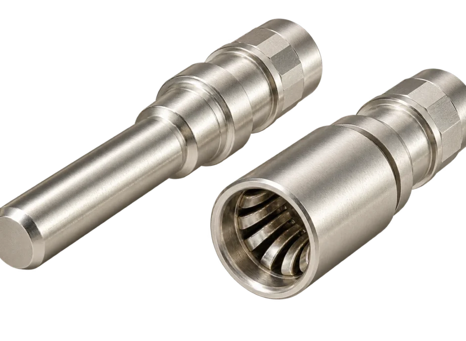
전기차 급속충전 커넥터 접점: 고전류를 받는 핀과 소켓의 구조
전기차 급속충전 커넥터 접점은 차량 인렛의 핀과 충전 플러그의 소켓이 만드는 고전류 인터페이스입니다. 눈에 잘 보이지 않는 접촉대, 도금과 케이블…
ID
18 10월 2026
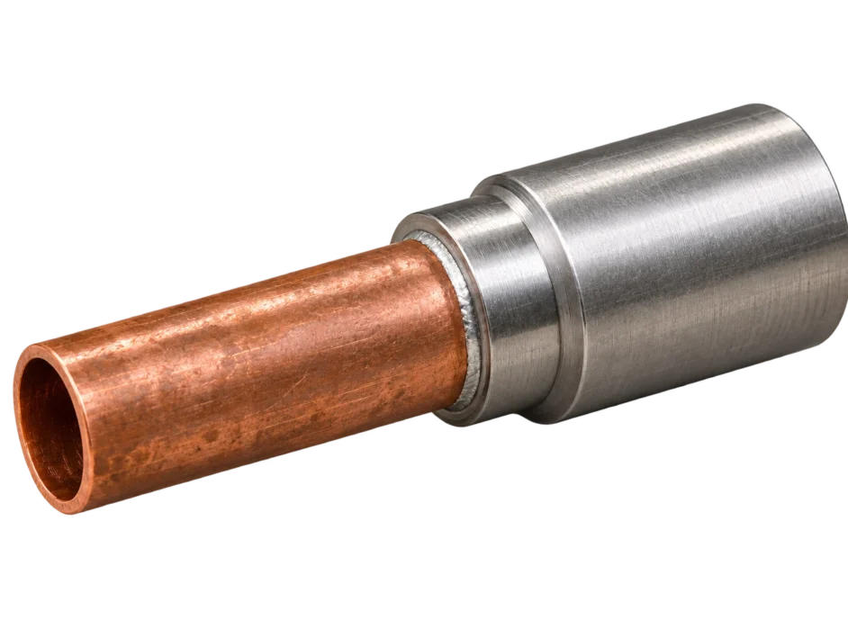
구리–스테인리스 이종 브레이징: 젖음·열간 간극·계면 내구성
구리–스테인리스 이종 브레이징 설계에서는 젖음, 열간 간극, 용가재와 공정 관리를 함께 검토해야 합니다.
ID
15 10월 2026

판금 루버 성형: 개구 형상·금형·압력손실을 연결하는 설계
루버는 판에 구멍을 많이 만드는 작업을 넘어, 절개한 재료를 원하는 방향으로 세워 공기의 통로와 패널의 구조를 함께 만드는 성형입니다.
ID
13 10월 2026
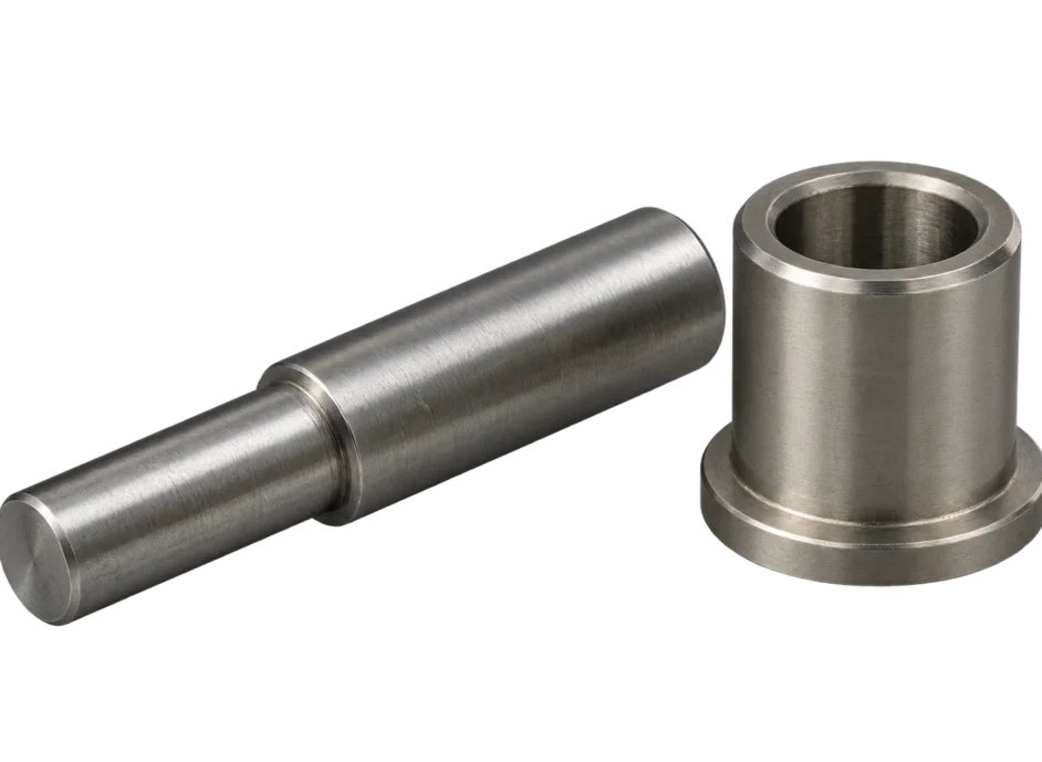
도금 공차 설계: 기능 치수·두께 분포·완성 검사
정밀 부품의 표면처리는 재료의 기능을 바꾸면서 조립 공간도 바꿉니다. 외경은 커지고 내경은 작아지며, 마스킹 경계와 국부 성장까지 상대 부품의 움직임에…
 ID
12 10월 2026

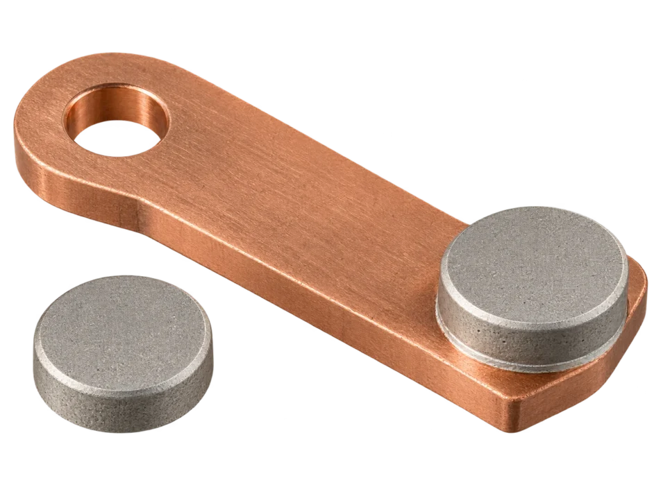
리벳 접점 조립품: 프레스 스프링·와이퍼 브러시의 설계와 품질관리
프레스 스프링과 와이퍼 브러시를 구성하는 리벳 접점 조립품의 구조·소재·리베팅 공정을 살펴보고, 접촉력·저항·마모를 연결해 설계와 품질관리의 핵심을 정리합니다.
