CONTACT FILM RESISTANCE
표면·힘·운동·계측으로 읽는 접촉저항
CONTACT FILM RESISTANCE
미세 도전점과 표면 이력을 실제 회로의 실패 조건에 연결합니다.
표면막 · 접촉력 · 미동 · 계측
표면막은 눈에 잘 보이지 않아도 실제 전류 경로를 바꿉니다.
막의 종류와 접촉력, 와이핑과 프레팅, 저레벨 검사와 열 시험을 연결해 초기값부터 사용 후 분포까지 해석합니다.
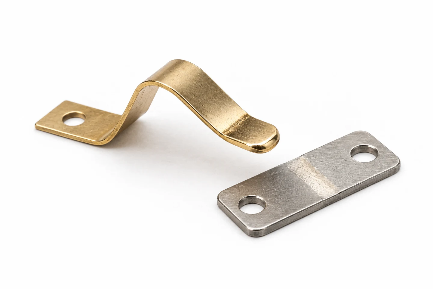
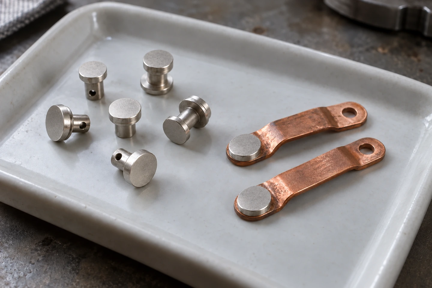
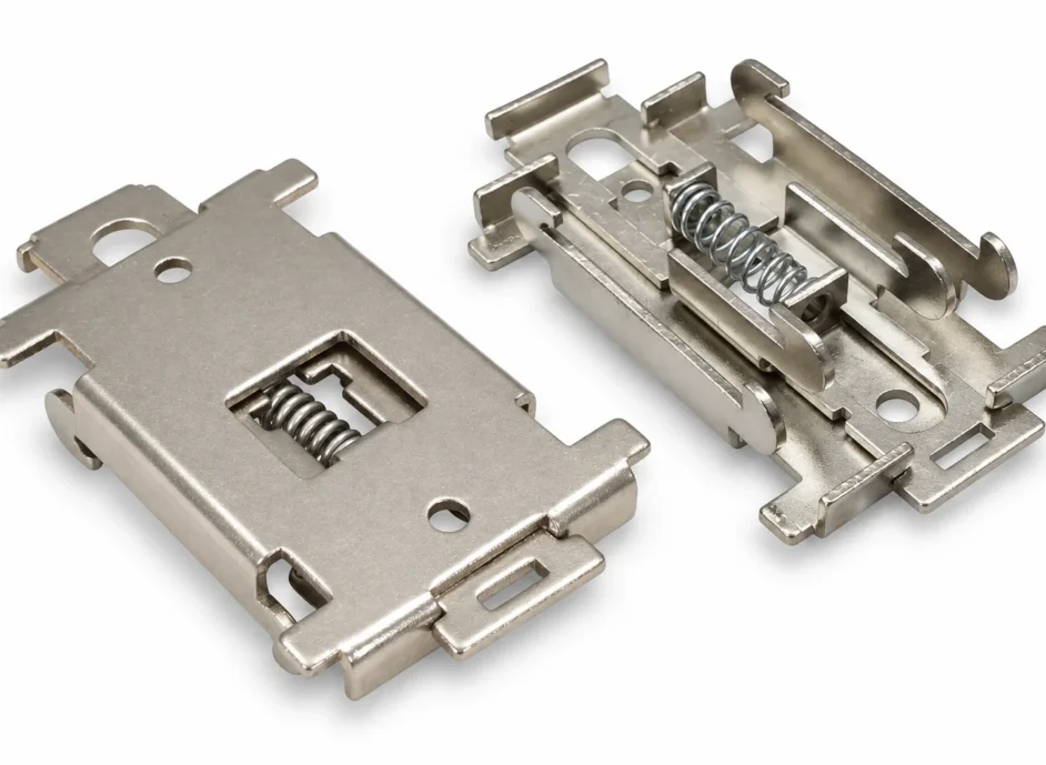
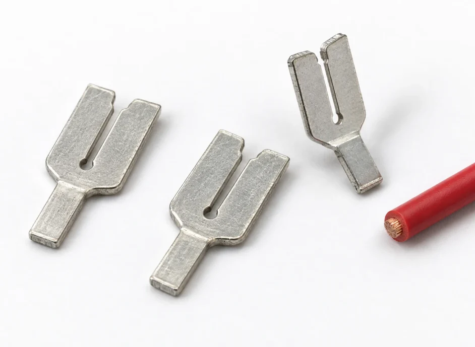
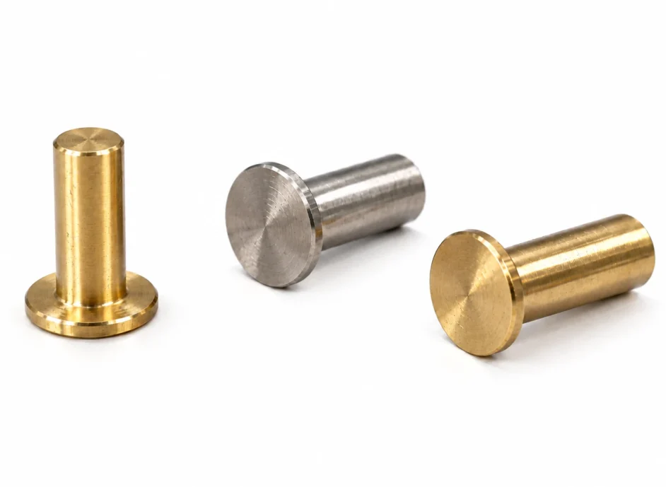
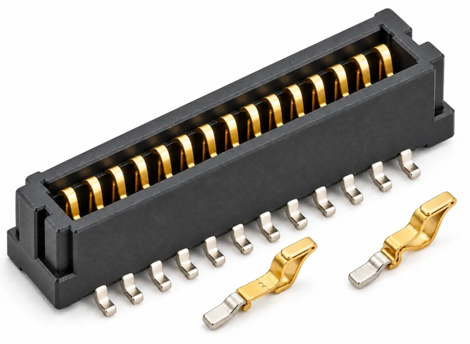
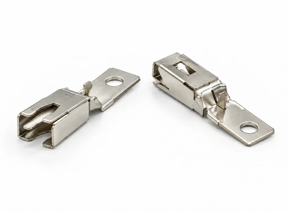
SURFACE VARIANTS / 접촉 리벳과 성형 블레이드
기능과 실제 전류 경로
같은 접점도 신호와 전력 회로에서 다르게 평가됩니다.
표면막은 접촉 금속 위에 생긴 산화물·황화물이나 유기 잔류층을 뜻합니다. 외관상 얇아도 전류가 지나갈 수 있는 경로를 바꾸므로, 모재의 전도율만으로 완성 접점의 저항을 예상하기 어렵습니다.
작은 신호에서는 짧은 불연속이 입력 오류가 될 수 있고, 연속 통전에서는 누적 발열이 문제가 될 수 있습니다. 개폐 접점에는 아크와 용착까지 추가되므로 사용 목적과 실패의 시간 척도를 먼저 정합니다.
시험계획에는 부하 종류, 허용 전압강하, 순간 불연속 시간과 측정 경계를 함께 넣습니다. 특정 검사기의 낮은 표시값을 목표로 삼으면 실제 회로에서 민감한 현상을 놓칠 수 있습니다.
입력 오류·간헐 불연속 · 허용 시간과 전압강하 정의
손실과 열 평형 · 실장·방열 조건 고정
아크·용착·개방 기능 · 실제 파형에서 별도 검증
| 검토 항목 | 기술적 의미 | 검증·관리 기준 |
|---|---|---|
| 신호 경로 | 입력 오류·간헐 불연속 | 허용 시간과 전압강하 정의 |
| 연속 통전 | 손실과 열 평형 | 실장·방열 조건 고정 |
| 부하 개폐 | 아크·용착·개방 기능 | 실제 파형에서 별도 검증 |
신호 경로
기술적 의미
입력 오류·간헐 불연속
검증·관리 기준
허용 시간과 전압강하 정의
연속 통전
기술적 의미
손실과 열 평형
검증·관리 기준
실장·방열 조건 고정
부하 개폐
기술적 의미
아크·용착·개방 기능
검증·관리 기준
실제 파형에서 별도 검증
접촉 자국과 실제 도전 면적을 구분합니다.
두 금속면은 미세 요철의 일부에서 먼저 닿습니다. 전류가 좁은 도전점으로 모였다가 퍼지는 수축저항과, 그 지점에 남은 막의 영향이 계면 저항에 함께 기여합니다.
접촉력을 바꾸면 돌기의 변형과 도전점 수가 달라지지만 그 관계는 곡률·경도·표면 이력에 영향을 받습니다. 큰 접촉 머리나 넓은 눌림 자국이 곧 동일 비율의 저항 감소를 뜻하지는 않습니다.
단자와 접합부가 포함된 측정값은 계면만의 저항보다 큰 경계를 나타냅니다. 불량 위치를 찾을 때에는 전압 검출점을 단계적으로 옮기되 접촉력과 온도를 유지하여 경계 변화의 영향을 분리합니다.
전류 집중 위치 · 힘·곡률·경도 함께 기록
도전 경로의 제약 · 재질·노출·운동 이력 확인
도체·접합부의 포함 여부 · 검출점 도면화
접촉 자국과 실제 도전 면적을 구분합니다.
전류 집중 위치 · 힘·곡률·경도 함께 기록
| 검토 항목 | 기술적 의미 | 검증·관리 기준 |
|---|---|---|
| 미세 도전점 | 전류 집중 위치 | 힘·곡률·경도 함께 기록 |
| 표면막 | 도전 경로의 제약 | 재질·노출·운동 이력 확인 |
| 측정 경계 | 도체·접합부의 포함 여부 | 검출점 도면화 |
미세 도전점
기술적 의미
전류 집중 위치
검증·관리 기준
힘·곡률·경도 함께 기록
표면막
기술적 의미
도전 경로의 제약
검증·관리 기준
재질·노출·운동 이력 확인
측정 경계
기술적 의미
도체·접합부의 포함 여부
검증·관리 기준
검출점 도면화
막의 종류와 힘의 범위
색만으로 성분이나 전기 기능을 확정하지 않습니다.
은은 황 성분이 있는 분위기에서 황화막을 형성할 수 있고, 노출된 구리나 주석에는 각각의 산화 거동이 나타납니다. 어떤 금속이 실제 접촉 자국에 드러나는지를 먼저 확인해야 막의 원인을 좁힐 수 있습니다.
유기 잔류물은 외관이 밝은 표면에도 남을 수 있습니다. 세정제·윤활제·포장재와 주변 수지의 이력을 추적하고, 필요하면 표면 분석으로 성분을 확인합니다. 사진만으로 오염 물질을 단정하지 않습니다.
마모분은 금속 조각과 반응 생성물이 섞인 제3의 접촉층이 될 수 있습니다. 이를 제거하기 전에 분포와 전기 상태를 기록해야 생성 원인과 재유입 경로를 조사할 수 있습니다.
황화 가능성 · 노출 환경과 기능값 대조
새로운 반응 표면 · 마모 위치·층 구조 확인
보이지 않는 오염 가능성 · 공정 이력·성분 분석
황화 가능성 · 노출 환경과 기능값 대조
| 검토 항목 | 기술적 의미 | 검증·관리 기준 |
|---|---|---|
| 은의 변색 | 황화 가능성 | 노출 환경과 기능값 대조 |
| 모재 노출 | 새로운 반응 표면 | 마모 위치·층 구조 확인 |
| 유기 잔류 | 보이지 않는 오염 가능성 | 공정 이력·성분 분석 |
| 마모분 | 제3체와 국부 차폐 | 원상태 분포 보존 |
은의 변색
기술적 의미
황화 가능성
검증·관리 기준
노출 환경과 기능값 대조
모재 노출
기술적 의미
새로운 반응 표면
검증·관리 기준
마모 위치·층 구조 확인
유기 잔류
기술적 의미
보이지 않는 오염 가능성
검증·관리 기준
공정 이력·성분 분석
마모분
기술적 의미
제3체와 국부 차폐
검증·관리 기준
원상태 분포 보존
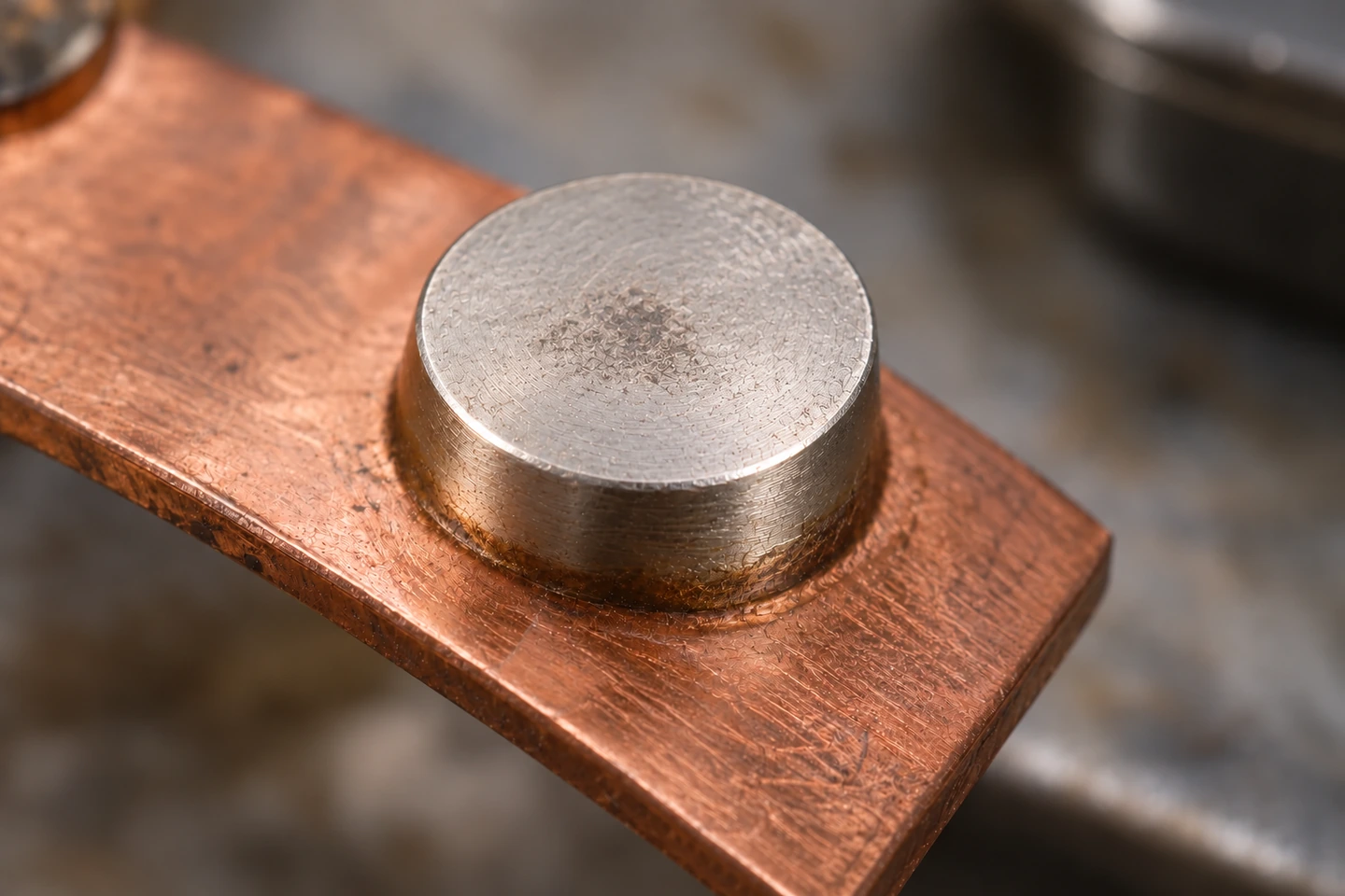
WORKING FACE / 접촉 머리의 표면 자국
04 / FORCE WINDOW
초기 가압값보다 유지되는 힘의 범위가 중요합니다.
접촉력은 미세 돌기의 변형과 접촉 안정성을 바꾸는 직접적인 변수입니다. 그러나 힘을 높이는 선택은 스프링 응력, 삽입력과 표면 압흔을 함께 바꾸므로 저항만으로 최적값을 정할 수 없습니다.
치수 편차와 장착 단차, 응력 완화와 마모는 사용 중 힘을 바꿉니다. 초기 조립에서 최대 힘만 확인하지 말고 최악 공차와 열 이력을 거친 뒤 최소 힘이 남는지 확인합니다.
불량 접점을 다시 누르면 저항이 회복될 수 있지만 이는 원인을 분리하는 시험입니다. 재가압 전 값을 보존하고, 힘 부족인지 막의 재배치인지 판단할 수 있도록 하중과 저항의 변화 곡선을 함께 기록합니다.
초기 가압값보다 유지되는 힘의 범위가 중요합니다.
| 검토 항목 | 기술적 의미 | 검증·관리 기준 |
|---|---|---|
| 초기 힘 | 도전점 형성 | 정의된 변위에서 측정 |
| 최소 힘 | 노화·공차의 영향 | 수명 조건 후 재확인 |
| 최대 힘 | 응력·압흔·삽입력 | 기계 한계와 비교 |
| 재가압 | 회복 원인의 분리 | 최초 결과 유지 |
초기 힘
기술적 의미
도전점 형성
검증·관리 기준
정의된 변위에서 측정
최소 힘
기술적 의미
노화·공차의 영향
검증·관리 기준
수명 조건 후 재확인
최대 힘
기술적 의미
응력·압흔·삽입력
검증·관리 기준
기계 한계와 비교
재가압
기술적 의미
회복 원인의 분리
검증·관리 기준
최초 결과 유지
하중 후의 넓어진 접촉점을 정성적으로 표시합니다. 접촉면적·응력·저항을 계산하지 않습니다.
표면 시스템과 청정도
밝고 매끄러운 외관이 접촉 안정성을 보증하지 않습니다.
거칠기는 실제 접촉점의 배치와 국부 압력에 영향을 줍니다. 평균 거칠기 하나로 돌기 곡률이나 가공 방향을 모두 표현할 수 없으므로 상대면과 운동 방향을 함께 확인합니다.
도금층은 기능 자국과 그 이동 범위에서 연속되어야 합니다. 굽힘 외측, 모서리와 마모 트랙의 결함을 분리해 보고, 평탄부 한 점의 두께만으로 가장 취약한 위치를 대표하지 않습니다.
더 거칠게 하거나 더 두껍게 하는 변경은 동일 상대재·힘·노출 조건에서 검증합니다. 목표는 특정 외관이 아니라 반복 후의 전기 안정성과 남은 기능층, 허용 가능한 마찰의 조합입니다.
접촉·미끄럼의 방향성 · 상대 운동과 대조
접촉 금속의 유지 · 트랙·굽힘부 관찰
모재 노출의 시작점 · 위치별 단면 확인
접촉·미끄럼의 방향성 · 상대 운동과 대조
| 검토 항목 | 기술적 의미 | 검증·관리 기준 |
|---|---|---|
| 가공 방향 | 접촉·미끄럼의 방향성 | 상대 운동과 대조 |
| 도금 연속성 | 접촉 금속의 유지 | 트랙·굽힘부 관찰 |
| 국부 결함 | 모재 노출의 시작점 | 위치별 단면 확인 |
| 공정 변경 | 표면 상태의 동시 변화 | 동일 조건의 대조 시험 |
가공 방향
기술적 의미
접촉·미끄럼의 방향성
검증·관리 기준
상대 운동과 대조
도금 연속성
기술적 의미
접촉 금속의 유지
검증·관리 기준
트랙·굽힘부 관찰
국부 결함
기술적 의미
모재 노출의 시작점
검증·관리 기준
위치별 단면 확인
공정 변경
기술적 의미
표면 상태의 동시 변화
검증·관리 기준
동일 조건의 대조 시험
세척은 관리 공정이면서 시편 상태를 바꾸는 개입입니다.
입고 불량을 바로 닦으면 오염과 마모분의 증거가 사라질 수 있습니다. 사진, 최초 저항, 보관 시간과 포장 상태를 먼저 남기고 세척 전후 시편을 구분하여 관리합니다.
세정액의 적합성뿐 아니라 헹굼, 건조와 이후 취급이 표면 상태를 결정합니다. 지정한 윤활제나 보호 처리를 세척으로 제거한 경우에는 공정 조건 자체가 달라졌음을 기록해야 합니다.
포장 검증은 청정한 시편을 실제 포장재와 보관 조건에 노출한 뒤 수행합니다. 보관 후 첫 작동과 반복 작동을 따로 측정하면 운전 중 회복되는 표면 문제를 놓치지 않을 수 있습니다.
원인 조사 증거 · 세척 전 사진·저항
잔류물과 재오염 · 액·시간·건조 이력
지정 표면 처리 · 제거 여부 명시
원인 조사 증거 · 세척 전 사진·저항
| 검토 항목 | 기술적 의미 | 검증·관리 기준 |
|---|---|---|
| 원상태 | 원인 조사 증거 | 세척 전 사진·저항 |
| 세정·헹굼 | 잔류물과 재오염 | 액·시간·건조 이력 |
| 윤활·보호막 | 지정 표면 처리 | 제거 여부 명시 |
| 보관 후 첫 작동 | 정지 노출의 영향 | 반복값과 분리 기록 |
원상태
기술적 의미
원인 조사 증거
검증·관리 기준
세척 전 사진·저항
세정·헹굼
기술적 의미
잔류물과 재오염
검증·관리 기준
액·시간·건조 이력
윤활·보호막
기술적 의미
지정 표면 처리
검증·관리 기준
제거 여부 명시
보관 후 첫 작동
기술적 의미
정지 노출의 영향
검증·관리 기준
반복값과 분리 기록
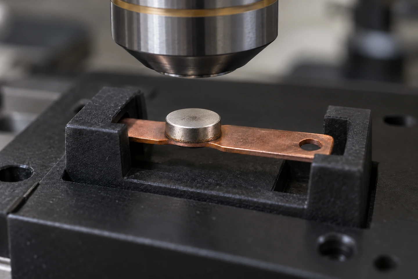
OPTICAL INSPECTION / 지지된 접촉면의 광학 관찰
상대 운동과 정밀 계측
막을 밀어내는 운동도 반복되면 마모원을 만듭니다.
의도된 와이핑은 접촉 과정에서 표면을 상대 이동시켜 막을 밀거나 깨는 데 도움을 줄 수 있습니다. 거리는 접촉 자국이 기능층 안에 머물고 필요한 힘이 유지되는 구간으로 정합니다.
체결 후 진동이나 열팽창 차이로 반복되는 미동은 별도 현상입니다. 특히 주석계에서는 표면 노출과 재산화, 마모분 축적이 반복되어 초기 저항이 낮아도 사용 중 불안정해질 수 있습니다.
하우징 지지와 도체 배치, 접촉력과 적합한 윤활을 함께 검토합니다. 운동 진폭만 줄인 시편과 마찰만 바꾼 시편을 구분하면 개선이 구조 안정화에서 왔는지 표면 보호에서 왔는지 판단하기 쉽습니다.
초기 막의 재배치 · 거리·힘·영역 확인
프레팅과 마모분 · 진폭·주파수·방향 기록
운동 전달 경로 · 하우징·전선 구속 검토
막을 밀어내는 운동도 반복되면 마모원을 만듭니다.
초기 막의 재배치 · 거리·힘·영역 확인
| 검토 항목 | 기술적 의미 | 검증·관리 기준 |
|---|---|---|
| 삽입 와이핑 | 초기 막의 재배치 | 거리·힘·영역 확인 |
| 반복 미동 | 프레팅과 마모분 | 진폭·주파수·방향 기록 |
| 구조 지지 | 운동 전달 경로 | 하우징·전선 구속 검토 |
| 윤활 후보 | 마찰과 표면 보호 | 노화 후 잔존·기능 검사 |
삽입 와이핑
기술적 의미
초기 막의 재배치
검증·관리 기준
거리·힘·영역 확인
반복 미동
기술적 의미
프레팅과 마모분
검증·관리 기준
진폭·주파수·방향 기록
구조 지지
기술적 의미
운동 전달 경로
검증·관리 기준
하우징·전선 구속 검토
윤활 후보
기술적 의미
마찰과 표면 보호
검증·관리 기준
노화 후 잔존·기능 검사
전압선은 전류 인입점 안쪽에 별도로 닿습니다. 접촉력과 측정 경계를 고정합니다.
4선식 연결만으로 모든 오차가 사라지지는 않습니다.
4선식은 전류 공급 경로와 전압 검출 경로를 나눕니다. 검출점 바깥의 리드 전압강하 영향을 줄이지만 시편의 접촉력, 검출점 위치와 열기전력은 여전히 관리해야 합니다.
작은 신호의 표면 상태를 평가할 때에는 검사 전류와 개방회로전압을 제한하고 시험 순서를 고정합니다. 먼저 큰 전류를 흘려 막을 바꾼 뒤 얻은 저항을 최초 저레벨 상태로 보고하지 않습니다.
계산 예로 일정한 0.10 A에서 정방향 +120 μV, 역방향 −80 μV를 얻었다면 저항은 1.00 mΩ입니다. 두 측정 사이 오프셋이 일정하고 접점이 선형·안정 상태라는 가정이며, 시간에 따라 바뀌는 막이나 자체 발열은 이 계산으로 제거되지 않습니다.
R: 검출점 사이 저항(Ω), V₊·V₋: 같은 검출 극성에서 ±I를 인가해 읽은 전압(V), I: 전류 크기(A). 두 측정 사이 오프셋과 접촉 상태가 일정할 때 적용합니다.
시편 상태의 보존 · 시험 순서와 함께 지정
| 검토 항목 | 기술적 의미 | 검증·관리 기준 |
|---|---|---|
| 전류·전압 제한 | 시편 상태의 보존 | 시험 순서와 함께 지정 |
| 검출 위치 | 포함 저항의 경계 | 지그 도면과 고정 |
| 극성 반전 | 안정 오프셋의 상쇄 | 정착 시간·대칭 전류 |
| 불확도 | 작은 신호의 해석 | 표준 저항·반복성 확인 |
전류·전압 제한
기술적 의미
시편 상태의 보존
검증·관리 기준
시험 순서와 함께 지정
검출 위치
기술적 의미
포함 저항의 경계
검증·관리 기준
지그 도면과 고정
극성 반전
기술적 의미
안정 오프셋의 상쇄
검증·관리 기준
정착 시간·대칭 전류
불확도
기술적 의미
작은 신호의 해석
검증·관리 기준
표준 저항·반복성 확인
발열과 환경 노출
저항이 같아도 방열 경계가 다르면 온도는 달라집니다.
닫힌 경로의 저항은 통전 손실에 기여하지만 온도 상승은 도체와 실장부로 빠져나가는 열에도 좌우됩니다. 배선 길이, 단면과 냉각 조건을 바꾸면 같은 접점의 온도 결과도 달라질 수 있습니다.
국부 발열은 접촉력 유지와 표면 상태에 다시 영향을 줄 수 있습니다. 저항과 온도를 시간에 따라 함께 기록하고, 안정화가 충분하지 않은 중간값을 최종 열 평형으로 취급하지 않습니다.
신호 불연속을 찾는 빠른 기록과 열 평형을 보는 느린 기록은 필요한 대역폭이 다릅니다. 한 장비의 평균값만으로 두 목적을 해결하기보다 판정 시간과 기록 간격을 목적에 맞게 정합니다.
저항이 같아도 방열 경계가 다르면 온도는 달라집니다.
배선·실장·주변 온도 · 시험 구성 고정
| 검토 항목 | 기술적 의미 | 검증·관리 기준 |
|---|---|---|
| 열 경계 | 배선·실장·주변 온도 | 시험 구성 고정 |
| 시간 응답 | 가열과 안정화 | 온도·저항 동시 이력 |
| 국부 변화 | 힘·막·접합부의 영향 | 위치별 진단 |
| 기록 대역폭 | 순간 오류와 열 평형 | 판정 시간에 맞춤 |
열 경계
기술적 의미
배선·실장·주변 온도
검증·관리 기준
시험 구성 고정
시간 응답
기술적 의미
가열과 안정화
검증·관리 기준
온도·저항 동시 이력
국부 변화
기술적 의미
힘·막·접합부의 영향
검증·관리 기준
위치별 진단
기록 대역폭
기술적 의미
순간 오류와 열 평형
검증·관리 기준
판정 시간에 맞춤
같은 노출도 체결 상태와 첫 작동 여부에 따라 달라집니다.
습도·온도·부식성 분위기는 노출 금속과 주변 재료에 서로 다른 영향을 줍니다. 체결 상태인지 열린 상태인지, 전압이 인가되는지와 노출 시간까지 정해야 시험 결과를 해석할 수 있습니다.
환경 후 분해나 반복 작동은 막과 마모분의 배치를 바꿀 수 있습니다. 원상태 전기 검사를 먼저 하고 외관 관찰, 재작동과 세척 분석을 순차적으로 배치하면 증거의 연결이 유지됩니다.
가속 노출 시간만으로 현장 연수를 환산하지 않습니다. 실제 포장과 설치 환경, 작동 빈도의 관련성을 확인하고 서로 다른 노출 조합이 같은 고장 경로를 만드는지 비교합니다.
환경 침투와 보호 · 열림·닫힘 명시
노출 중 전위 조건 · 극성·전압·시간 기록
상태 변경의 영향 · 최초 검사 우선
환경 침투와 보호 · 열림·닫힘 명시
| 검토 항목 | 기술적 의미 | 검증·관리 기준 |
|---|---|---|
| 체결 상태 | 환경 침투와 보호 | 열림·닫힘 명시 |
| 전기 바이어스 | 노출 중 전위 조건 | 극성·전압·시간 기록 |
| 검사 순서 | 상태 변경의 영향 | 최초 검사 우선 |
| 현장 관련성 | 가속 시험의 적용 범위 | 고장 형태 비교 |
체결 상태
기술적 의미
환경 침투와 보호
검증·관리 기준
열림·닫힘 명시
전기 바이어스
기술적 의미
노출 중 전위 조건
검증·관리 기준
극성·전압·시간 기록
검사 순서
기술적 의미
상태 변경의 영향
검증·관리 기준
최초 검사 우선
현장 관련성
기술적 의미
가속 시험의 적용 범위
검증·관리 기준
고장 형태 비교
원인 분석과 양산 이관
평균이 낮아도 기능 실패가 없다는 뜻은 아닙니다.
검사 결과에는 평균뿐 아니라 최대값, 분포와 불연속 발생 횟수를 포함합니다. 순간 최대값은 계측 대역폭과 판정 시간에 따라 달라지므로 기록 설정도 결과의 일부입니다.
저항 증가가 생긴 시편은 접촉 자국 이동, 잔존층, 마모분과 결합부를 함께 봅니다. 외관 이상과 전기 이상이 같은 위치에서 시작했는지 확인한 뒤 표면막·힘 부족·접합 문제를 구분합니다.
세척이나 재가압으로 회복된 결과는 최초 실패와 함께 보관합니다. 개선안은 새 시편에서 동일 노출과 순서를 반복해 확인해야 진단 과정에서 생긴 일시적 회복과 구별할 수 있습니다.
시편 간 변동 · 개별 추적 번호 유지
기능 오류의 시간성 · 대역폭·판정 시간 명시
원인 위치의 구분 · 전기 기록과 같은 시편
평균이 낮아도 기능 실패가 없다는 뜻은 아닙니다.
시편 간 변동 · 개별 추적 번호 유지
| 검토 항목 | 기술적 의미 | 검증·관리 기준 |
|---|---|---|
| 분포 | 시편 간 변동 | 개별 추적 번호 유지 |
| 불연속 | 기능 오류의 시간성 | 대역폭·판정 시간 명시 |
| 표면·결합부 | 원인 위치의 구분 | 전기 기록과 같은 시편 |
| 회복 시험 | 진단 개입의 효과 | 최초 실패와 함께 보존 |
분포
기술적 의미
시편 간 변동
검증·관리 기준
개별 추적 번호 유지
불연속
기술적 의미
기능 오류의 시간성
검증·관리 기준
대역폭·판정 시간 명시
표면·결합부
기술적 의미
원인 위치의 구분
검증·관리 기준
전기 기록과 같은 시편
회복 시험
기술적 의미
진단 개입의 효과
검증·관리 기준
최초 실패와 함께 보존
저항 요구에는 측정 조건과 시편 이력이 따라야 합니다.
도면에는 모재와 접촉층, 기능영역, 접촉력 범위와 운동 조건을 연결합니다. 표면 청정도나 외관 기준은 허용 결함의 위치와 검사 방법이 있어야 생산에서 일관되게 적용됩니다.
검사 절차에는 검출점, 전류·전압 제한, 온도, 정착 시간과 세척 여부를 넣습니다. 제품 요구와 측정시스템의 반복성을 구분하면 계측 변화로 공정을 불필요하게 조정하는 일을 줄일 수 있습니다.
재료 공급처, 도금욕, 윤활제와 포장재 변경은 표면 이력을 바꿀 수 있습니다. 변경 전후의 최초 작동·반복 운동·환경 후 결과를 비교하고 승인 시편과 로트 기록을 보존합니다.
영역·힘·운동 · 도면과 시험 조건 연결
층·청정도·윤활 · 위치별 허용 기준
검출·여기·온도 · 작업표준과 교정 유지
영역·힘·운동 · 도면과 시험 조건 연결
| 검토 항목 | 기술적 의미 | 검증·관리 기준 |
|---|---|---|
| 기능 요구 | 영역·힘·운동 | 도면과 시험 조건 연결 |
| 표면 관리 | 층·청정도·윤활 | 위치별 허용 기준 |
| 검사 조건 | 검출·여기·온도 | 작업표준과 교정 유지 |
| 변경 승인 | 재료·공정·포장 | 비교 검증과 이력 보존 |
기능 요구
기술적 의미
영역·힘·운동
검증·관리 기준
도면과 시험 조건 연결
표면 관리
기술적 의미
층·청정도·윤활
검증·관리 기준
위치별 허용 기준
검사 조건
기술적 의미
검출·여기·온도
검증·관리 기준
작업표준과 교정 유지
변경 승인
기술적 의미
재료·공정·포장
검증·관리 기준
비교 검증과 이력 보존
회로 조건, 접촉재·층 구조, 힘·운동 범위와 저항 판정 조건을 보내주세요.
Provide circuit conditions, material and layer stack, force and motion range, and resistance acceptance criteria.
CONTACT FILM RESISTANCE
Connect conducting spots and surface history to actual circuit failure conditions.
FILMS · FORCE · MOTION · METROLOGY
ENGLISH EDITION
Review the initial state and distributions after service.
A film can change the real current path without being visually obvious.
Connect film chemistry, force, wiping and fretting with low-level measurements and thermal tests to interpret initial readings and distributions after service.
SURFACE VARIANTS / Contact rivets and formed blades
Function and real current paths
The same interface is evaluated differently in signal and power circuits.
A surface film may consist of oxide, sulfide or organic residue on the contact metal. Even a visually inconspicuous layer changes available conducting paths, so bulk conductivity alone cannot predict the resistance of an assembled interface.
A short interruption may corrupt a small signal, while sustained power conduction can be limited by accumulated heating. Switching adds arcs and welding. Define the function and the relevant failure duration before selecting a resistance limit.
The test plan should state load type, allowable voltage drop, interruption duration and measurement boundary. Optimizing a low meter reading without these conditions can miss the behavior that actually matters to the circuit.
Input error and intermittency. Define duration and voltage drop
Loss and thermal equilibrium. Fix mounting and heat removal
Arc, weld and opening. Validate with actual waveform
| Review item | Engineering significance | Verification or control |
|---|---|---|
| Signal path | Input error and intermittency | Define duration and voltage drop |
| Continuous conduction | Loss and thermal equilibrium | Fix mounting and heat removal |
| Loaded switching | Arc, weld and opening | Validate with actual waveform |
Signal path
Engineering significance
Input error and intermittency
Verification or control
Define duration and voltage drop
Continuous conduction
Engineering significance
Loss and thermal equilibrium
Verification or control
Fix mounting and heat removal
Loaded switching
Engineering significance
Arc, weld and opening
Verification or control
Validate with actual waveform
Distinguish the visible contact mark from conducting area.
Two metal faces initially touch at selected asperities. Current converges into these small conducting spots and then spreads out again. Constriction resistance and the films remaining at these spots both contribute to interface resistance.
Changing force alters asperity deformation and the number of conducting spots, with curvature, hardness and surface history influencing the response. A larger head or indentation does not imply a proportional reduction in resistance.
A reading that includes terminals and joints describes a wider boundary than the interface alone. During diagnosis, move sense points systematically while maintaining force and temperature so the effect of the measurement boundary can be separated.
Current concentration. Record force, curvature and hardness
Restriction of conducting paths. Check material, exposure and motion
Included conductors and joints. Draw sense locations
Distinguish the visible contact mark from conducting area.
Current concentration. Record force, curvature and hardness
| Review item | Engineering significance | Verification or control |
|---|---|---|
| Conducting spots | Current concentration | Record force, curvature and hardness |
| Film | Restriction of conducting paths | Check material, exposure and motion |
| Measurement boundary | Included conductors and joints | Draw sense locations |
Conducting spots
Engineering significance
Current concentration
Verification or control
Record force, curvature and hardness
Film
Engineering significance
Restriction of conducting paths
Verification or control
Check material, exposure and motion
Measurement boundary
Engineering significance
Included conductors and joints
Verification or control
Draw sense locations
Film chemistry and force window
Color alone cannot establish chemistry or electrical function.
Silver can form sulfide films in sulfur-containing atmospheres, while exposed copper and tin have their own oxidation behavior. Identifying the metal actually present in the contact track helps narrow the possible film mechanisms.
Organic residue can remain on an apparently bright surface. Trace cleaners, lubricants, packaging and surrounding polymers, then use surface analysis when chemical identification is needed. A photograph alone cannot identify the contaminant.
Wear debris can become a third-body layer containing metal fragments and reaction products. Record its distribution and the electrical condition before removal so its generation and return to the contact zone can be investigated.
Possible sulfide formation. Compare exposure and function
New reactive surface. Check wear position and stack
Potential invisible contamination. Trace process and chemistry
Possible sulfide formation. Compare exposure and function
| Review item | Engineering significance | Verification or control |
|---|---|---|
| Silver tarnish | Possible sulfide formation | Compare exposure and function |
| Base exposure | New reactive surface | Check wear position and stack |
| Organic residue | Potential invisible contamination | Trace process and chemistry |
| Wear debris | Third-body screening | Preserve as-found distribution |
Silver tarnish
Engineering significance
Possible sulfide formation
Verification or control
Compare exposure and function
Base exposure
Engineering significance
New reactive surface
Verification or control
Check wear position and stack
Organic residue
Engineering significance
Potential invisible contamination
Verification or control
Trace process and chemistry
Wear debris
Engineering significance
Third-body screening
Verification or control
Preserve as-found distribution
WORKING FACE / Surface witness on a contact head
04 / FORCE WINDOW
The maintained force range matters beyond initial loading.
Force directly affects asperity deformation and mechanical stability. Increasing it also changes spring stress, insertion force and surface indentation, so resistance alone cannot establish the optimum setting.
Dimensional variation, mounting steps, stress relaxation and wear can change force during service. Verify the remaining minimum force after adverse tolerances and thermal exposure, rather than checking only the maximum at assembly.
Reloading a failed contact may restore a low reading, but this is a diagnostic intervention. Preserve the original reading and record force and resistance together to distinguish insufficient loading from film redistribution.
The maintained force range matters beyond initial loading.
| Review item | Engineering significance | Verification or control |
|---|---|---|
| Initial force | Conducting-spot formation | Measure at defined travel |
| Minimum force | Aging and tolerance effects | Recheck after service exposure |
| Maximum force | Stress, marking and insertion | Compare mechanical limits |
| Reloading | Diagnostic recovery | Retain original result |
Initial force
Engineering significance
Conducting-spot formation
Verification or control
Measure at defined travel
Minimum force
Engineering significance
Aging and tolerance effects
Verification or control
Recheck after service exposure
Maximum force
Engineering significance
Stress, marking and insertion
Verification or control
Compare mechanical limits
Reloading
Engineering significance
Diagnostic recovery
Verification or control
Retain original result
Expanded spots illustrate loading qualitatively without calculating contact area, stress or resistance.
Surface system and cleanliness
A bright smooth appearance does not certify contact stability.
Roughness influences conducting-spot distribution and local pressure. A single average roughness value cannot describe asperity curvature or machining direction completely; review the counterface and direction of motion as well.
The coating must remain continuous across the functional scar and its movement envelope. Assess bend exteriors, edges and wear tracks separately; one thickness reading on a convenient flat area cannot represent every vulnerable location.
Validate roughness or thickness changes under matched counterface, force and exposure conditions. The objective is a combination of electrical stability after cycling, retained working layer and acceptable friction, rather than a particular appearance.
Contact and sliding orientation. Compare relative motion
Retention of contact metal. Inspect track and bends
Potential base exposure. Check location-specific sections
Contact and sliding orientation. Compare relative motion
| Review item | Engineering significance | Verification or control |
|---|---|---|
| Texture direction | Contact and sliding orientation | Compare relative motion |
| Coating continuity | Retention of contact metal | Inspect track and bends |
| Local defects | Potential base exposure | Check location-specific sections |
| Process change | Coupled surface changes | Use matched comparison tests |
Texture direction
Engineering significance
Contact and sliding orientation
Verification or control
Compare relative motion
Coating continuity
Engineering significance
Retention of contact metal
Verification or control
Inspect track and bends
Local defects
Engineering significance
Potential base exposure
Verification or control
Check location-specific sections
Process change
Engineering significance
Coupled surface changes
Verification or control
Use matched comparison tests
Cleaning is both a control process and a specimen intervention.
Immediately wiping a rejected part can remove evidence of residue or debris. First record photographs, initial resistance, storage duration and packaging, then distinguish specimens tested before and after cleaning.
Rinsing, drying and subsequent handling matter alongside cleaner compatibility. If cleaning removes specified lubricant or protective treatment, record that the process condition itself has changed.
Evaluate packaging by exposing clean specimens to the actual packaging and storage conditions. Separate the first operation after storage from subsequent operations so a surface problem that recovers with use is not overlooked.
Diagnostic evidence. Photograph and measure first
Residue and recontamination. Record liquid, time and drying
Specified surface condition. Declare any removal
Diagnostic evidence. Photograph and measure first
| Review item | Engineering significance | Verification or control |
|---|---|---|
| As found | Diagnostic evidence | Photograph and measure first |
| Clean and rinse | Residue and recontamination | Record liquid, time and drying |
| Lubricant or treatment | Specified surface condition | Declare any removal |
| First operation | Effect of idle exposure | Separate from repeat readings |
As found
Engineering significance
Diagnostic evidence
Verification or control
Photograph and measure first
Clean and rinse
Engineering significance
Residue and recontamination
Verification or control
Record liquid, time and drying
Lubricant or treatment
Engineering significance
Specified surface condition
Verification or control
Declare any removal
First operation
Engineering significance
Effect of idle exposure
Verification or control
Separate from repeat readings
OPTICAL INSPECTION / Observation of a supported contact face
Relative motion and precision measurement
Motion that displaces film can also generate wear.
Intentional wipe during engagement can help displace or disrupt a film. Define the stroke so the contact scar stays inside the working finish while the required force is maintained.
Micromotion after mating, driven by vibration or differential expansion, is a separate mechanism. Tin systems can repeatedly expose and oxidize fresh material while accumulating debris, despite an initially low resistance.
Review housing support, conductor routing, force and suitable lubrication together. Separating specimens with reduced motion from those with altered friction helps identify whether improvement came from structural stability or surface protection.
Initial film displacement. Check travel, force and zone
Fretting and debris. Record amplitude, rate and direction
Motion transmission. Review housing and wire restraint
Motion that displaces film can also generate wear.
Initial film displacement. Check travel, force and zone
| Review item | Engineering significance | Verification or control |
|---|---|---|
| Insertion wipe | Initial film displacement | Check travel, force and zone |
| Micromotion | Fretting and debris | Record amplitude, rate and direction |
| Structural support | Motion transmission | Review housing and wire restraint |
| Lubricant candidate | Friction and surface protection | Check retention and function after aging |
Insertion wipe
Engineering significance
Initial film displacement
Verification or control
Check travel, force and zone
Micromotion
Engineering significance
Fretting and debris
Verification or control
Record amplitude, rate and direction
Structural support
Engineering significance
Motion transmission
Verification or control
Review housing and wire restraint
Lubricant candidate
Engineering significance
Friction and surface protection
Verification or control
Check retention and function after aging
Sense leads contact independently inside the current connections; hold force and sensing boundaries fixed.
Four-wire connection does not remove every error.
Four-wire measurement separates current injection from voltage sensing. It reduces the influence of lead drops outside the sense points, but specimen force, sense position and thermoelectric offsets still require control.
When assessing small-signal surface behavior, limit test current and open-circuit voltage and fix the test sequence. A reading obtained after a larger current has altered the film does not represent the initial low-level state.
For an illustrative constant current of 0.10 A, readings of +120 μV and −80 μV give 1.00 mΩ. This assumes stable offset between readings and a linear, unchanged interface. Changing films or self-heating are not canceled by the calculation.
R: resistance between sense points (Ω); V₊ and V₋: signed voltages with unchanged sense polarity under ±I (V); I: current magnitude (A). Applicable when offset and contact condition stay constant between readings.
Preservation of specimen state. Specify with test order
| Review item | Engineering significance | Verification or control |
|---|---|---|
| Excitation limits | Preservation of specimen state | Specify with test order |
| Sense location | Resistance boundary | Fix in fixture drawing |
| Polarity reversal | Stable-offset cancellation | Control settling and equal current |
| Uncertainty | Small-signal interpretation | Check reference and repeatability |
Excitation limits
Engineering significance
Preservation of specimen state
Verification or control
Specify with test order
Sense location
Engineering significance
Resistance boundary
Verification or control
Fix in fixture drawing
Polarity reversal
Engineering significance
Stable-offset cancellation
Verification or control
Control settling and equal current
Uncertainty
Engineering significance
Small-signal interpretation
Verification or control
Check reference and repeatability
Heating and environmental exposure
Equal resistance does not imply equal temperature.
Closed-path resistance contributes to power loss, while temperature rise also depends on heat flow into conductors and mounting. Changing lead length, section or cooling can change the thermal result for the same interface.
Local heating can feed back into force retention and surface condition. Record resistance and temperature over time, and avoid interpreting an intermediate reading as thermal equilibrium before adequate settling.
Rapid recording for signal interruptions and slow recording for thermal equilibrium require different bandwidths. Select acceptance duration and sampling interval for each purpose instead of relying on a single averaged instrument reading.
Equal resistance does not imply equal temperature.
Leads, mounting and ambient. Fix test configuration
| Review item | Engineering significance | Verification or control |
|---|---|---|
| Thermal boundary | Leads, mounting and ambient | Fix test configuration |
| Time response | Heating and settling | Record temperature and resistance |
| Local change | Force, film and joint effects | Diagnose by location |
| Recording bandwidth | Interruptions and thermal state | Match acceptance duration |
Thermal boundary
Engineering significance
Leads, mounting and ambient
Verification or control
Fix test configuration
Time response
Engineering significance
Heating and settling
Verification or control
Record temperature and resistance
Local change
Engineering significance
Force, film and joint effects
Verification or control
Diagnose by location
Recording bandwidth
Engineering significance
Interruptions and thermal state
Verification or control
Match acceptance duration
Exposure depends on mating state and prior operation.
Humidity, temperature and corrosive atmospheres affect exposed metals and surrounding materials differently. Specify mated or open state, electrical bias and duration to make the result interpretable.
Disassembly or repeated operation after exposure can rearrange film and debris. Measuring electrically as found, then inspecting, cycling and cleaning in a planned sequence preserves the chain of evidence.
Do not convert accelerated exposure time directly into years in service. Establish relevance to packaging, installation and operating frequency, and compare whether different exposure combinations produce the same failure mechanism.
Ingress and shielding. Declare open or mated
Potential during exposure. Record polarity, voltage and time
Effect of intervention. Prioritize as-found measurement
Ingress and shielding. Declare open or mated
| Review item | Engineering significance | Verification or control |
|---|---|---|
| Mating state | Ingress and shielding | Declare open or mated |
| Electrical bias | Potential during exposure | Record polarity, voltage and time |
| Inspection order | Effect of intervention | Prioritize as-found measurement |
| Service relevance | Accelerated-test boundary | Compare failure morphology |
Mating state
Engineering significance
Ingress and shielding
Verification or control
Declare open or mated
Electrical bias
Engineering significance
Potential during exposure
Verification or control
Record polarity, voltage and time
Inspection order
Engineering significance
Effect of intervention
Verification or control
Prioritize as-found measurement
Service relevance
Engineering significance
Accelerated-test boundary
Verification or control
Compare failure morphology
Diagnosis and production transfer
A low mean does not prove absence of functional failures.
Include distributions, maxima and interruption counts alongside the mean. Recorded peaks depend on bandwidth and duration criteria, so acquisition settings are part of the result.
For specimens showing resistance growth, examine track movement, remaining finish, debris and joints. Establish whether electrical and visible changes began at the same location before distinguishing film, force and joining problems.
Retain recovery after cleaning or reloading together with the original failure. Verify corrective changes on fresh specimens under the same exposure and sequence to distinguish durable improvement from temporary diagnostic recovery.
Between-specimen variation. Retain individual identity
Time-dependent function error. State bandwidth and duration
Location of mechanism. Use electrically tracked specimens
A low mean does not prove absence of functional failures.
Between-specimen variation. Retain individual identity
| Review item | Engineering significance | Verification or control |
|---|---|---|
| Distribution | Between-specimen variation | Retain individual identity |
| Interruption | Time-dependent function error | State bandwidth and duration |
| Surface and joint | Location of mechanism | Use electrically tracked specimens |
| Recovery test | Effect of intervention | Preserve with original failure |
Distribution
Engineering significance
Between-specimen variation
Verification or control
Retain individual identity
Interruption
Engineering significance
Time-dependent function error
Verification or control
State bandwidth and duration
Surface and joint
Engineering significance
Location of mechanism
Verification or control
Use electrically tracked specimens
Recovery test
Engineering significance
Effect of intervention
Verification or control
Preserve with original failure
Resistance requirements need conditions and specimen history.
Link substrate, working layer, functional area, force range and motion conditions in the drawing package. Cleanliness and appearance criteria need defect locations and inspection methods to be applied consistently in production.
Specify sense points, excitation limits, temperature, settling time and cleaning state in the inspection procedure. Separating product requirements from measurement repeatability reduces unnecessary process adjustment in response to measurement variation.
Changes to material supply, plating bath, lubricant or packaging can change surface history. Compare first-operation, cycling and post-exposure behavior before and after a change, retaining approval specimens and lot records.

Zone, force and motion. Link drawing and test
Layers, cleanliness and lubricant. Set location-specific criteria
Sensing, excitation and temperature. Maintain procedure and calibration
Zone, force and motion. Link drawing and test
| Review item | Engineering significance | Verification or control |
|---|---|---|
| Functional requirement | Zone, force and motion | Link drawing and test |
| Surface control | Layers, cleanliness and lubricant | Set location-specific criteria |
| Inspection condition | Sensing, excitation and temperature | Maintain procedure and calibration |
| Change approval | Material, process and packaging | Compare and retain history |
Functional requirement
Engineering significance
Zone, force and motion
Verification or control
Link drawing and test
Surface control
Engineering significance
Layers, cleanliness and lubricant
Verification or control
Set location-specific criteria
Inspection condition
Engineering significance
Sensing, excitation and temperature
Verification or control
Maintain procedure and calibration
Change approval
Engineering significance
Material, process and packaging
Verification or control
Compare and retain history
표면막 관리는 세척 한 단계로 끝나지 않습니다. 회로가 허용하는 오류, 실제 도전점, 힘과 운동, 검사 에너지와 노출 순서를 함께 정의해야 재현 가능한 저항 데이터를 얻을 수 있습니다.
01 / 회로의 허용 전압강하와 불연속 시간을 먼저 정합니다.
02 / 겉보기 자국과 실제 도전 면적을 구분합니다.
03 / 힘의 최소·최대와 노화 후 여유를 검증합니다.
04 / 삽입 와이핑과 사용 중 미동을 따로 시험합니다.
05 / 검사 전류·전압과 측정 순서로 표면 상태를 보존합니다.
06 / 세척·재가압 전의 최초 실패를 기록합니다.
07 / 표면·포장 변경을 기능 검증에 연결합니다.
색만으로 판정하지 않습니다. 원상태를 보존하고 해당 회로의 저항·불연속 기준에서 확인합니다.
도전점 형성에는 도움이 될 수 있으나 마모·응력·삽입력도 바뀝니다. 수명 조건에서 힘의 범위를 검증합니다.
검출점 사이의 도체·접합부·계면이 모두 포함될 수 있습니다. 검출 위치를 도면으로 정합니다.
신호가 커질 수 있지만 시편을 가열하거나 막을 바꿀 수 있습니다. 평가 목적에 맞는 제한이 필요합니다.
삽입 중 의도된 이동과 체결 후 반복 미동은 목적과 누적 영향이 다릅니다. 각각의 거리·힘·횟수를 정의합니다.
회복은 원인 분석 자료입니다. 최초 실패를 보존하고 지정된 사용 상태에서 새 시편으로 재검증합니다.
대역폭·샘플링·판정 시간을 일치시켜야 합니다. 평균값과 개별 시편 이력도 함께 봅니다.
목적에 따라 다르지만 최초 작동 상태를 먼저 기록해야 반복 작동으로 사라지는 문제를 보존할 수 있습니다.
기능 트랙의 두께와 노출 금속을 함께 봅니다.
하우징과 도체가 접점에 전달하는 운동을 줄입니다.
측정 민감도와 시편 상태 보존을 함께 설계합니다.
표면막접촉저항황화산화접촉력와이핑프레팅4선식열기전력청정도환경 시험
Film control extends beyond cleaning. Define circuit tolerance, conducting spots, force, motion, test energy and exposure sequence together to obtain reproducible resistance data.
01 / Define allowable circuit drop and interruption duration first.
02 / Distinguish the visible scar from conducting area.
03 / Verify minimum, maximum and aged force margin.
04 / Test insertion wipe and service micromotion separately.
05 / Preserve surface state through excitation limits and test order.
06 / Record initial failure before cleaning or reloading.
07 / Connect surface and packaging changes to functional validation.
Color is insufficient. Preserve the as-found state and apply the circuit resistance and interruption criteria.
It can help form conducting spots but also changes wear, stress and insertion force. Validate a force window through service exposure.
Conductors, joints and interface between the sense points may all contribute. Define those points on a drawing.
It may increase signal but can heat the specimen or alter the film. Limits must match the test purpose.
Intentional engagement motion and repeated mated micromotion have different purposes and cumulative effects. Define each stroke, force and cycle count.
Recovery is diagnostic evidence. Preserve initial failure and revalidate fresh specimens in the specified service state.
Match bandwidth, sampling and duration criteria. Review means and individual histories alongside peaks.
It depends on purpose, but record first-operation behavior before cycling removes evidence of an idle-exposure problem.
Review track thickness together with exposed metal.
Control motion transmitted through housing and conductors.
Balance sensitivity with preservation of specimen condition.
Surface filmsContact resistanceSulfidationOxidationContact forceWipingFrettingFour-wireThermal EMFCleanlinessEnvironmental testing
연결 준비 중입니다. 현재 전화 연결을 이용하실 수 있습니다.