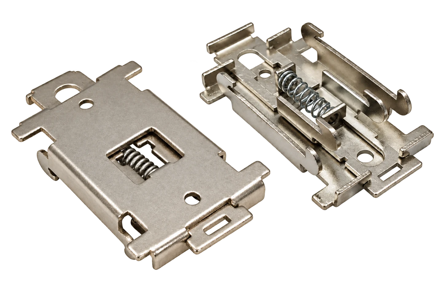
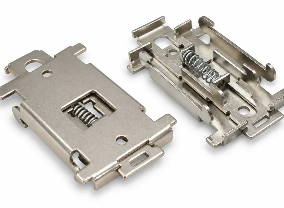
장착 홀과 슬라이딩 래치를 갖춘 DIN 레일 고정클립

DIN RAIL MOUNTING CLIPS

제어반 DIN 레일
고정클립

걸리는 형상과 잠기는 동작. 작은 프레스 부품이 장착을 완성합니다.

장착 홀과 슬라이딩 래치를 갖춘 DIN 레일 고정클립

Hook.
Slide.
Lock.

DIN RAIL MOUNTING CLIPS

장착 홀과 슬라이딩 래치를 갖춘 DIN 레일 고정클립

레일에 걸고.
래치로 잠그고.

몸체와 가동 래치의 맞물림부터 장비·배선이 전달하는 힘까지, 고정클립의 제조와 조립 조건을 살펴봅니다.

HOOK · SLIDE · LOCK · VERIFY

Overview.

레일 맞물림·슬라이딩 래치·조립체 하중의 연결

DIN 레일 고정클립 하나가 제어반 장비의 설치 방식을 결정합니다. 센서 인터페이스, 통신 모듈이나 소형 계측 장치를 추가할 때, 장치 뒤편에 나사로 고정한 작은 금속 조립품이 레일의 양쪽 가장자리를 붙잡습니다. 외형은 단순해 보여도 장비 무게를 받는 부분, 잠금을 유지하는 부분, 정비할 때 움직이는 부분은 역할이 다릅니다.

이 글은 프레스 강판 몸체에 슬라이딩 래치와 압축 코일 스프링을 조립한 35 mm 레일용 구조를 중심으로 살펴봅니다. 몸체를 크게 휘어 끼우는 일체형 판스프링이나 단자대 끝을 막는 엔드 스토퍼와는 다릅니다. 레일 치수와 걸림 형상에서 시작해 성형 편차, 장치의 하중, 조립 후 기능을 차례로 연결하면 어떤 부품을 그대로 적용할 수 있고 어느 부분을 새로 설계해야 하는지 판단하기 쉬워집니다.

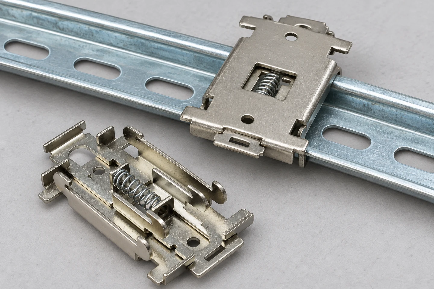
DIN 레일에 교차 장착한 고정클립과 분리된 클립의 뒷면

RAIL ENGAGEMENT / 35 mm 레일과 고정클립의 맞물림

01 / THE MOUNTING INTERFACE

35 mm라는 폭에서, 실제로 맞물리는 단면으로

35 mm DIN 레일을 쓴다는 사실만으로 모든 클립이 같은 조건에서 장착되지는 않습니다. 같은 폭의 톱햇 레일에도 높이 7.5 mm와 15 mm 형상이 있습니다. 레일 높이는 장치 뒤쪽 공간과 설치판으로부터의 거리에 영향을 주고, 가장자리 두께와 형상은 클립의 걸림 깊이와 유격에 관여합니다. 레일과 클립의 단면을 함께 겹쳐 봐야 나사 머리나 장치 하우징까지 포함한 간섭을 찾을 수 있습니다.

DIN 레일 고정클립의 장착면은 장치에서 받은 힘을 몸체로 전달합니다. 몸체의 고정 걸림부는 레일 한쪽 립을 붙잡고, 가동 래치는 반대쪽 립의 이탈 경로를 막습니다. 따라서 장치의 체결 구멍이 맞는 것과 레일에 안정적으로 고정되는 것은 서로 다른 조건입니다. 구멍 위치만 맞춰 부품을 대체하면 래치가 닿기 전에 나사가 레일에 걸리거나, 장치가 해제 손잡이를 가리는 문제가 남을 수 있습니다.

레일을 따라 옆으로 움직이지 않게 하는 엔드 스토퍼도 별도로 봅니다. 고정클립은 장치와 레일을 연결하고, 엔드 스토퍼는 정해진 위치에서 부품 열의 이동을 제한합니다. 클립이 레일에서 빠지지 않는다고 레일 길이 방향의 미끄러짐까지 모두 억제하는 것은 아닙니다. 수직 레일이나 무거운 배선이 있는 배치에서는 어느 부품이 그 방향의 힘을 받는지 먼저 정해야 합니다.

규격화된 레일의 기계 장착 인터페이스는 호환성을 검토하는 출발점입니다. 그러나 장치의 허용 무게, 진동 조건과 보호접지 성능을 하나로 보증하는 등급은 아닙니다. 금속 클립이 금속 레일에 닿아 있다는 이유만으로 PE 경로가 확보되었다고 판단하지 않고, 접지 기능이 필요한 장치는 해당 제품의 전기적 연결과 검증 조건을 따로 확인합니다.

강판 몸체 안에서 움직이는 래치와 복귀 스프링

INTERACTIVE 3D / STRUCTURE
ID SOLUTECH / 01
3D 모델 준비 중
스프링 분리

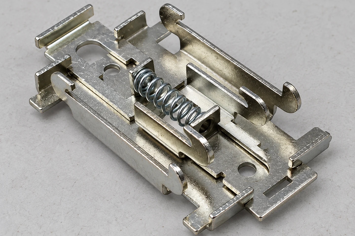
코일 스프링은 몸체 쪽 받침과 래치 쪽 받침 사이에 놓입니다. 래치를 당기면 두 받침 사이가 좁아지고, 손을 놓으면 스프링이 래치를 되돌립니다.

드래그·방향키 회전 · +/− 확대 · Home 초기 시점부품의 결합 관계와 안내 구조를 살펴봅니다.
02 / CONTROLLED LATCH TRAVEL

몸체를 휘는 대신, 래치가 움직여 잠금을 풉니다

이 구조에서 크게 움직이는 부품은 몸체 안의 슬라이더입니다. 압축 코일 스프링은 슬라이더를 잠금 방향으로 되돌리고, 가이드와 스토퍼는 이동 경로와 끝 위치를 정합니다. 레일을 붙잡는 힘을 모두 스프링의 누르는 힘으로 설명해서는 안 됩니다. 걸림부가 립 뒤에 겹쳐져 이탈 경로를 막는 형상, 몸체의 강성, 장치 체결 상태가 함께 작동합니다.

래치 해제형은 고정 걸림부를 한쪽 립에 건 뒤 해제부를 조작해 가동 걸림부의 공간을 확보하고, 장치를 레일 쪽으로 앉힌 다음 래치를 복귀시켜 잠급니다. 분리할 때는 래치를 충분히 이동시켜 반대 립에서 벗어나게 한 후 가동부 쪽을 바깥으로 기울이고 고정 걸림부를 빼냅니다. 이 순서를 쓰는 부품을 억지로 들어 올려 빼면 걸림부나 레일이 손상될 수 있습니다. 실제 조립 작업에서는 채택한 제품의 방향과 조작 방법을 기준으로 삼습니다.

잠금 위치에서는 립과 걸림부가 필요한 만큼 겹쳐야 하고, 해제 위치에서는 조립 편차가 있어도 립을 지나갈 여유가 있어야 합니다. 스트로크를 늘리는 것만으로 두 조건이 동시에 좋아지지는 않습니다. 해제 손잡이의 공간, 스프링 압축 한계와 슬라이더 이탈 방지까지 영향을 받기 때문입니다. 장치 뒤에서 손이나 공구가 들어갈 통로도 이때 함께 확보합니다.

작동감을 검사할 때는 끝 위치뿐 아니라 움직이는 과정도 봅니다. 도금이 쌓인 가이드, 한쪽으로 치우친 스프링, 슬라이더의 뒤틀림은 중간 걸림을 만들 수 있습니다. 걸림이 있다가 갑자기 풀리는 부품은 손을 놓았을 때 완전히 복귀하지 않을 수 있으므로, 조작력과 복귀 상태를 이동 전 구간에서 확인해야 합니다.

걸기·진입·잠금·해제, 래치의 이동 순서

INTERACTIVE 3D / LATCH RELEASE
ID SOLUTECH / 02
3D 모델 준비 중
두 립 잠금

몸체가 자리 잡은 뒤 래치를 놓으면 복귀 스프링이 가동 걸림턱을 되돌립니다. 고정턱과 가동턱이 양쪽 립을 함께 잡습니다.

드래그·방향키 회전 · +/− 확대 · Home 초기 시점래치를 조작하는 방식의 장착·해제 동작을 보여줍니다.
03 / STAMPED PARTS THAT MUST MOVE

프레스 정밀도는 외곽 치수보다 움직이는 간극에서 드러납니다

몸체는 지지와 안내를, 슬라이더는 잠금과 해제를 담당합니다. 두 판재 부품을 같은 재료·두께로 만들어야 하는 것은 아니며, 별도로 조립하는 코일 스프링의 재질과 열처리 조건도 몸체와 구분합니다. 외형이 비슷한 강판을 바꾸더라도 강도와 재질 상태가 달라지면 굽힘 후 각도와 평탄도가 달라질 수 있습니다. 재료를 정할 때는 성형성, 사용 환경과 필요한 강성을 함께 봅니다.

블랭킹에서는 레일을 받는 가장자리와 슬라이더 가이드의 절단면이 중요합니다. 버가 안내면으로 향하면 작동이 거칠어지고, 레일 립을 긁는 모서리는 표면 손상과 마모 분진의 출발점이 될 수 있습니다. 도면에는 단순히 버 제거라고 적는 데서 그치지 않고 기능면, 허용 버와 모서리 처리 범위를 지정하는 편이 낫습니다. 지나친 연마로 걸림부의 유효 길이나 단면이 줄어드는 것도 피해야 합니다.

굽힘에서는 펀치·다이 형상, 판 두께, 굽힘 반경과 소재 방향이 완성 각도에 함께 영향을 줍니다. 금형 안의 각도와 하중을 제거한 뒤의 각도는 같지 않을 수 있어, 스프링백 보정은 실제 소재 상태와 공정으로 확인해야 합니다. 특히 가이드 두 곳의 평행도나 마주 보는 걸림부 간격은 개별 각도가 허용 범위여도 조립하면 빡빡해질 수 있습니다. 단품 치수 검사와 실제 슬라이딩 기능 검사가 함께 필요한 이유입니다.

표면처리 후에도 이 관계를 다시 확인합니다. 마주 보는 면에 코팅 두께가 더해지면 작동 간극이 줄고, 날카로운 모서리나 홈에서는 두께 분포가 균일하지 않을 수 있습니다. 열처리를 적용하는 재질이라면 처리 후 변형과 표면 상태까지 포함해 공정 순서를 정합니다. 도금 전 치수가 합격이어도 완성품의 래치가 부드럽게 돌아온다는 보장은 없습니다.

DIN 레일 클립 뒷면의 압축 코일 스프링과 가이드 절곡부

LATCH MECHANISM / 가동 래치의 안내부와 압축 코일 스프링

04 / THE DEVICE LOAD PATH

장비 무게와 함께, 힘이 들어오는 위치를 봅니다

같은 무게의 장치라도 무게중심이 레일에서 멀어지면 고정부를 벌리는 모멘트가 커집니다. 케이블을 한쪽으로 꺾거나 커넥터를 빼는 동작도 장치를 비틀거나 레일에서 떼어내는 방향으로 작용할 수 있습니다. 힘과 그 작용선까지의 수직 거리의 곱으로 모멘트를 비교할 수 있지만, 이 계산만으로 클립의 허용 하중을 정할 수는 없습니다. 실제 힘의 방향과 지지 위치, 변형과 걸림 유지 상태까지 연결해야 합니다.

레일 길이 방향으로 미는 힘, 설치면에서 당겨 떼는 힘, 장치를 회전시키는 힘은 서로 다른 고장 경로를 만듭니다. 미끄러짐을 억제한 시험만으로 들림 방향의 이탈을 보증하지 않고, 한 방향의 정적 시험을 통과했다고 진동 중 래치가 움직이지 않는다고 결론내리지 않습니다. 장치의 설치 방향을 바꾸거나 케이블 출구를 옮길 때에도 원래의 검증 조건이 유지되는지 살펴야 합니다.

클립 두 개를 쓰면 하중이 정확히 절반씩 나뉜다고 가정하기도 어렵습니다. 장치의 체결면 평탄도와 구멍 위치, 레일의 휨 때문에 한쪽이 먼저 닿을 수 있기 때문입니다. 레일을 설치판에 고정한 나사 간격과 레일 자체의 강성도 전체 움직임에 영향을 줍니다. 클립만 단단한 블록에 고정한 시험과 실제 제어반 레일에 조립한 시험은 다른 경계조건을 갖습니다.

배선은 장착 검토의 마지막 부속물이 아닙니다. 케이블을 받치는 위치와 여유 길이를 조정하면 클립에 전달되는 비틀림을 줄일 수 있지만, 배선을 지나치게 당겨 정리하면 반대로 지속적인 외력을 만들 수 있습니다. 장치 무게, 무게중심, 배선 경로와 정비 시 힘을 한 장착 조건으로 정리해야 클립 형상만 바꾸는 수정이 필요한지, 주변 지지 구조를 고치는 편이 나은지 판단할 수 있습니다.

05 / EXISTING PART OR NEW DESIGN

표준품 적용과 신규 제작은 도면의 같은 지점에서 갈립니다

기존 규격품을 활용할 수 있다면 먼저 장치 도면과 레일 단면을 대조합니다. 검토 가능한 보유품이나 공급품이 있을 때에도 폭과 장착 구멍만 보고 맞는다고 결정하지 않습니다. 잠금 방식, 해제 손잡이의 접근 공간, 사용 방향과 표면처리가 적용 조건에 들어오는지까지 확인해야 합니다. 호환 범위를 벗어난 부분이 하나라도 있으면 어댑터를 추가하는 방법과 클립 자체를 바꾸는 방법을 함께 검토합니다.

어댑터 판은 기존 클립의 구멍을 유지할 수 있지만 장치가 레일에서 더 멀어질 수 있습니다. 반대로 구멍 위치를 바꾼 새 클립은 부품 수를 줄일 수 있어도 금형과 기능 검증이 새로 필요합니다. 이 선택은 외형이 더 간단한 쪽으로만 정할 일이 아닙니다. 장착 깊이, 하중 경로, 조립 공정과 필요한 수량을 함께 봐야 변경의 범위가 분명해집니다.

신규 제작의 출발 자료는 장치 체결면, 레일 규격과 공차, 요구 조작 공간, 하중 조건이 포함된 도면입니다. 여기에 소재와 표면처리, 목표 수량, 검사 기준을 연결해 프레스 성형 순서와 금형 구성을 검토합니다. 샘플 하나가 끼워진다는 사실은 양산 치수 편차에서도 잠금과 해제가 반복된다는 뜻이 아닙니다. 초기 샘플에서는 간극과 걸림부의 조정 가능 범위를 확인하고, 이후 완성 공정으로 만든 조립품에서 기능을 다시 검증합니다.

적용 여부를 결정하는 네 가지 도면 대조

대조 위치함께 확인할 조건변경 시 다시 볼 부분
장치 체결면구멍·기준면·나사 머리와 끝단 공간체결 강도, 뒤틀림, 레일·래치 간섭
레일 걸림부립 형상·두께·겹침과 잠금 상태조립 편차에서의 유격·이탈 경로
해제 조작부작업 접근 방향·필요 이동량주변 장치·배선과의 간섭, 완전 복귀
장치와 배선무게중심·외력·설치 방향클립 수·배치, 레일 지지, 엔드 스토퍼

함께 확인할 조건 · 변경 시 다시 볼 부분

장치 체결면
구멍·기준면·나사 머리와 끝단 공간
체결 강도, 뒤틀림, 레일·래치 간섭
레일 걸림부
립 형상·두께·겹침과 잠금 상태
조립 편차에서의 유격·이탈 경로
해제 조작부
작업 접근 방향·필요 이동량
주변 장치·배선과의 간섭, 완전 복귀
장치와 배선
무게중심·외력·설치 방향
클립 수·배치, 레일 지지, 엔드 스토퍼
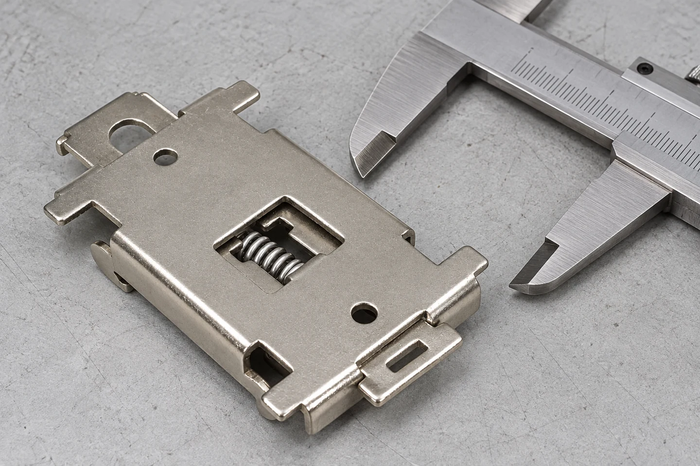
치수 검토를 위해 캘리퍼 옆에 놓은 DIN 레일 고정클립

CLIP INSPECTION / 치수 검토를 위한 부품과 측정 도구

06 / VERIFY THE COMPLETE ASSEMBLY

치수 합격 다음에는 잠금·해제·유지를 확인합니다

완성품 검사에서는 레일 기준으로 장착면, 고정 걸림부와 가동 래치의 위치를 읽어야 합니다. 외곽 치수와 구멍 검사는 캘리퍼스나 측정 장비로 할 수 있지만, 걸림 깊이와 해제 여유는 기능에 맞는 게이지나 대표 레일 조건이 필요합니다. 허용 공차의 불리한 조합을 포함해 검토하고, 보기 좋은 한 개의 레일에만 맞춰 합격 기준을 만들지 않습니다.

탈착을 반복한 뒤에는 조작력 변화, 래치의 복귀, 걸림부 변형과 마모를 봅니다. 처음에는 잠기지만 반복 후 가이드가 닳아 기울거나, 스프링이 치우쳐 끝까지 돌아오지 않는 경우를 구별해야 합니다. 탈착 횟수와 작동 속도, 온도 조건은 목표 사용 수명에 맞춰 정하며, 시험을 한 번 통과한 수치를 다른 재질·두께·도금의 수명으로 옮기지 않습니다.

진동과 충격 검증은 장치, 클립, 레일, 고정 나사와 배선을 포함한 조립 상태를 기준으로 계획합니다. 시험 방법이 정해져 있어도 주파수·가속도·시간·방향과 합격 기준은 실제 환경과 제품 요구에 맞춰야 합니다. 시험 전후의 걸림 겹침, 잔류 변형, 풀림과 정상 해제 여부를 비교하고, 기능을 유지했는지까지 기록해야 결과가 다음 설계 변경에 쓰일 수 있습니다.

조립품 검사에서 남길 기능 기록

검증 단계관찰 항목기록할 조건
장착·해제걸림 겹침, 이동 중 걸림, 해제 여유와 복귀레일 단면, 조작 방향, 장치 체결 상태
정적 외력미끄러짐·들림·회전, 잔류 변형힘의 방향·작용점, 레일 지지와 배선
반복 작동조작력 변화, 마모, 스프링과 가이드 상태횟수·속도·온도, 시험 전후 동일 측정점
진동·충격잠금 유지, 나사 풀림, 시험 후 정상 작동조립 구성, 시험 방향·조건과 합격 기준

관찰 항목 · 기록할 조건

장착·해제
걸림 겹침, 이동 중 걸림, 해제 여유와 복귀
레일 단면, 조작 방향, 장치 체결 상태
정적 외력
미끄러짐·들림·회전, 잔류 변형
힘의 방향·작용점, 레일 지지와 배선
반복 작동
조작력 변화, 마모, 스프링과 가이드 상태
횟수·속도·온도, 시험 전후 동일 측정점
진동·충격
잠금 유지, 나사 풀림, 시험 후 정상 작동
조립 구성, 시험 방향·조건과 합격 기준

DIN 레일 고정클립의 완성도는 금속 부품이 한 번 끼워지는 모습보다, 장치가 힘을 받는 동안 잠금을 유지하고 정비할 때 의도한 방법으로 풀리는지에서 드러납니다. 레일에 맞는 걸림 형상, 움직이는 간극, 프레스·후처리 편차와 실제 조립 하중을 함께 관리할 때 작은 부품의 역할이 분명해집니다.

Start a
Project.

궁금한 사항은 아래 문의 양식으로 남겨 주세요.

Please use the form below to send your enquiry.

개발 상담 · Contact

기술 협의 · Engineering Consultation
도면과 사양을 기준으로 소재·가공·표면처리,
주요 품질 항목과 공급 조건을 함께 검토합니다.


We review drawings and specifications to define materials, manufacturing methods, surface finishes, key quality requirements, and supply conditions.

개발 의뢰하기 · Development Inquiry

    도면 및 기술자료 *
    Drawings & Technical Documents *

    도면 번호와 개정 이력이 표시된 2D·3D 도면을 첨부해 주세요.
    사양서와 검사 기준도 함께 전달할 수 있습니다.
    Attach your 2D or 3D drawings with their drawing numbers and revisions.
    Include specifications and inspection criteria as needed.

    파일을 이곳에 놓아주세요Drag & drop your files here

    선택된 파일 없음 / No files attached

    최대 5개 · 파일당 5MB · 총 15MB / Up to 5 files · 5MB each · 15MB total
    PDF · DWG · DXF · STEP/STP · IGS/IGES · JPG · PNG · ZIP

    * 필수 입력 / Required fields

    DIN RAIL MOUNTING CLIPS

    장착 홀과 슬라이딩 래치를 갖춘 DIN 레일 고정클립

    Hook onto the rail.
    Lock with the latch.

    Follow the stamped body and moving latch from engagement geometry to the forces transmitted by the device and its cables.

    HOOK · SLIDE · LOCK · VERIFY

    ENGLISH EDITION

    DIN Rail
    Mounting Clips

    Support at the hook. Retention at the latch. Stamped parts complete the mounting interface.

    Connecting rail engagement, a sliding latch and assembly loads

    When a sensor interface, communication module or compact measuring device is added to a control panel, the DIN rail mounting clip behind it determines how the device is installed. A small metal assembly, screwed to the device, engages the two edges of the rail. Its appearance can hide three different functions: supporting the equipment, retaining engagement and moving deliberately during maintenance.

    This article follows a 35 mm rail arrangement built from a stamped steel body, a sliding latch and a compression coil spring. It differs from a one-piece flexing spring clip and from an end stop beside a terminal-block row. Starting with the rail and hook geometry, then relating forming variation to device loads and finished-assembly operation, provides a practical basis for choosing an existing part or identifying the features that need a new design.

    DIN 레일에 교차 장착한 고정클립과 분리된 클립의 뒷면

    RAIL ENGAGEMENT / Mounting clip engaged with a 35 mm rail

    01 / THE MOUNTING INTERFACE

    From a 35 mm nominal width to the section that actually engages

    Using a 35 mm DIN rail does not make every clip interchangeable under the same conditions. Top-hat rails of that nominal width include 7.5 mm and 15 mm height profiles. Rail height affects the space behind the device and its distance from the mounting plate, while the lip section affects hook engagement and play. Overlaying the rail and clip sections also reveals interference involving screw heads and the device housing.

    The mounting face transfers force from the device into the clip body. Fixed hooks engage one rail lip; a moving latch obstructs escape from the opposite lip. Matching the device’s mounting holes and establishing stable rail retention are therefore separate requirements. A replacement chosen by hole position alone can leave a screw touching the rail before seating is complete, or place the release handle behind an inaccessible part of the housing.

    An end stop has a separate role. The mounting clip connects the device to the rail, whereas an end stop limits movement of a row at a defined position. Resistance to pull-off does not automatically establish resistance to sliding along the rail. With a vertical rail or a stiff cable bundle, identify which component is intended to carry the force in that direction.

    A standardized mechanical rail interface is the starting point for compatibility. It is not a combined rating for device mass, vibration resistance and protective earthing. Metal-to-metal contact between a clip and rail alone does not qualify a PE path. Equipment that uses the mounting arrangement for protective earthing requires a separate assessment of the electrical connection and the applicable product requirements.

    The sliding latch and return spring inside a stamped body

    INTERACTIVE 3D / STRUCTURE
    ID SOLUTECH / 01
    Preparing 3D model
    Spring separated

    The coil sits between a body-mounted seat and a latch-mounted seat. Pulling the latch shortens the distance between them; release allows the spring to return the latch.

    Drag / arrow keys to orbit · +/− to zoom · Home to resetExplore the component arrangement and the latch guides.
    02 / CONTROLLED LATCH TRAVEL

    Release comes from latch travel, not from bending the entire body

    The main moving component is the slider inside the body. A compression coil spring returns it toward the locked position, while guides and stops define its path and end positions. Retention cannot be explained by spring force alone. Hook overlap behind the lip, body stiffness and attachment to the device all contribute to preventing escape.

    For the latch-release arrangement, engage the fixed hooks, actuate the release to clear the moving hooks, seat the device against the rail and allow the latch to return. Removal reverses the engagement: retract the moving hooks, tilt that side outward and lift the fixed hooks clear. A part designed for this sequence can be damaged by forcibly lifting it off without releasing the latch. Production work must follow the orientation and operating method of the selected component.

    At the locked position, the hooks need sufficient overlap with the rail lips. At the released position, the moving hooks need clearance despite assembly variation. Increasing stroke does not improve both conditions without consequences: it also affects handle space, spring compression and slider retention. The route by which a hand or tool reaches the release behind the device belongs in the same review.

    Evaluate the whole travel, not only its end positions. Coating accumulation on a guide, an offset spring or a distorted slider can cause binding midway. A mechanism that sticks and then breaks free may fail to return fully when released. Operating force and complete return should therefore be checked throughout the usable travel, including the assembled condition.

    Hook, enter, lock and release: the latch sequence

    INTERACTIVE 3D / LATCH RELEASE
    ID SOLUTECH / 02
    Preparing 3D model
    Lock both lips

    Once the body is seated, release the latch. The return spring restores the sliding hooks, so the fixed and moving hooks engage both rail lips.

    Drag / arrow keys to orbit · +/− to zoom · Home to resetFollow the mounting and removal motion of a latch-release clip.
    03 / STAMPED PARTS THAT MUST MOVE

    Stamping accuracy becomes visible in the moving clearances

    The body supports and guides; the slider locks and releases. These two sheet-metal parts need not share the same material or thickness, and the separate coil spring has its own material and heat-treatment specification. Substituting a visually similar steel sheet can change the final bend angle and flatness because strength and material condition differ. Formability, environment and required stiffness belong in the material decision together.

    During blanking, attention should concentrate on the rail-bearing edges and slider guides. Burrs facing a guide can roughen travel; an edge that scratches the rail can initiate finish damage and debris. A drawing should identify the functional surfaces, permitted burrs and edge-treatment limits instead of relying solely on a general deburring note. Excessive finishing can also shorten effective hook overlap or reduce a load-bearing section.

    Tool geometry, thickness, bend radius and material direction influence the finished bend. The angle under load in the tool may differ from the unloaded angle, so springback compensation requires the actual material condition and process. Guide parallelism and the distance between opposing hooks are assembly dimensions: individually acceptable bends can still produce a tight slider. Finished-part measurement needs to be connected to a functional travel check.

    Repeat that assessment after surface treatment. Coating on opposing faces reduces clearance, and edges or recessed features may not receive uniform thickness. Where heat treatment is specified, include subsequent distortion and surface condition when choosing the process sequence. A dimension that passed before plating does not establish that the completed latch will return smoothly.

    DIN 레일 클립 뒷면의 압축 코일 스프링과 가이드 절곡부

    LATCH MECHANISM / Sliding guidance and compression coil spring

    04 / THE DEVICE LOAD PATH

    Where a force enters matters as much as the device mass

    Two devices of equal mass can impose different opening moments when their centres of gravity sit at different distances from the rail. Bending a cable to one side or disconnecting a plug can also twist the device or pull it away from the mounting plane. Force multiplied by its perpendicular lever arm helps compare moments, but that calculation alone does not establish a clip load rating. Force direction, support locations, deformation and retained engagement must also be considered.

    A force along the rail, a pull away from the mounting plane and a twisting moment can create different failure paths. A test that restrains sliding does not prove resistance to peel-off, and passing a static load in one direction does not establish that a latch remains engaged during vibration. Changing the installation orientation or cable exit can therefore change the relevance of earlier verification.

    Two clips do not necessarily share the load equally. Mounting-face flatness, hole position and rail curvature can make one side contact first. Rail stiffness and the spacing of the screws fastening it to the mounting plate also affect assembly movement. A clip tested on a rigid block and a clip installed on the actual panel rail do not have the same boundary conditions.

    Cables are part of the mounting assessment from the start. Appropriate support and spare length can reduce torque reaching the clip, whereas tightly dressing the bundle may apply a sustained force. Recording device mass, centre of gravity, cable routing and maintenance forces as one installation condition helps decide whether a clip redesign is needed or whether improving the surrounding support is more effective.

    05 / EXISTING PART OR NEW DESIGN

    Drawings show where an existing part stops being a direct fit

    When an existing standard part may be suitable, begin by comparing the device drawing with the rail section. Even an available stock or supplier part should not be accepted solely on width and hole spacing. Its locking method, release access, intended orientation and finish must also suit the application. A feature outside that scope can lead either to an adapter arrangement or to a change in the clip itself.

    An adapter plate may preserve the mounting holes of an existing clip while moving the device farther from the rail. A new clip with revised holes may reduce the component count but requires tooling review and functional qualification. The choice cannot be made from apparent simplicity alone. Mounting depth, load path, assembly work and required quantity define the actual extent of the change.

    A new design starts with the device attachment face, rail profile and tolerances, release-access envelope and load conditions. Material, finish, quantity and inspection criteria then inform the forming sequence and tooling arrangement. One sample fitting one rail does not demonstrate repeatable locking and release across production variation. Early samples establish adjustment needs; assemblies made by the intended final process establish whether those functions are maintained.

    Four drawing comparisons that establish application suitability

    InterfaceConditions to compareReview after a change
    Device attachmentHoles, datum face and space for screw heads and endsJoint strength, distortion and rail or latch interference
    Rail engagementLip profile, thickness, overlap and locked positionPlay and escape paths across assembly variation
    Release accessApproach direction and required travelNearby devices, cables and complete latch return
    Device and cablesCentre of gravity, external forces and orientationClip quantity and layout, rail support and end stops

    Conditions to compare · Review after a change

    Device attachment
    Holes, datum face and space for screw heads and ends
    Joint strength, distortion and rail or latch interference
    Rail engagement
    Lip profile, thickness, overlap and locked position
    Play and escape paths across assembly variation
    Release access
    Approach direction and required travel
    Nearby devices, cables and complete latch return
    Device and cables
    Centre of gravity, external forces and orientation
    Clip quantity and layout, rail support and end stops
    치수 검토를 위해 캘리퍼 옆에 놓은 DIN 레일 고정클립

    CLIP INSPECTION / Part and measuring tool prepared for dimensional inspection

    06 / VERIFY THE COMPLETE ASSEMBLY

    After dimensional acceptance, verify locking, release and retention

    Inspect the completed assembly from rail-related references: the mounting face, fixed hooks and moving latch. Calipers or measuring equipment can check external dimensions and holes, while engagement depth and release clearance require a functional gauge or representative rail conditions. Include unfavourable permitted tolerance combinations rather than defining acceptance around a single convenient rail sample.

    After repeated installation and removal, assess operating-force changes, latch return, hook deformation and wear. A part may lock initially yet develop tilted guidance or incomplete return after cycling. The cycle count, operating speed and temperature belong to the intended service-life requirement. A result from one material, thickness and finish should not be transferred to another assembly as an established life rating.

    Plan vibration and shock verification around the device, clips, rail, fasteners and cables as an assembly. A defined test method still needs application-specific frequency, acceleration, duration, directions and acceptance criteria. Compare engagement, permanent deformation, loosening and normal release before and after testing. Recording whether the required functions remain available makes the result useful when the design subsequently changes.

    Functional records for the finished assembly

    Verification stageObserveRecord the conditions
    Mount and releaseOverlap, binding during travel, release clearance and returnRail section, operating direction and device attachment
    Static external loadSliding, lift-off, rotation and permanent deformationForce direction and position, rail support and cables
    Repeated operationOperating-force change, wear, spring and guide conditionCycles, speed, temperature and consistent measurement locations
    Vibration and shockRetained lock, fastener loosening and operation after testingAssembly configuration, test directions, conditions and acceptance criteria

    Observe · Record the conditions

    Mount and release
    Overlap, binding during travel, release clearance and return
    Rail section, operating direction and device attachment
    Static external load
    Sliding, lift-off, rotation and permanent deformation
    Force direction and position, rail support and cables
    Repeated operation
    Operating-force change, wear, spring and guide condition
    Cycles, speed, temperature and consistent measurement locations
    Vibration and shock
    Retained lock, fastener loosening and operation after testing
    Assembly configuration, test directions, conditions and acceptance criteria

    A DIN rail mounting clip is judged by more than a successful first fit. It must retain engagement while the device is loaded and release by the intended method during maintenance. Matching hook geometry, controlled moving clearances, forming and finishing variation, and the loads of the actual assembly establishes what this small component needs to do.

    ADDITIONAL INFORMATION

    추가 정보

    핵심 요약

    DIN 레일 고정클립은 장치를 레일에 연결하는 기계 부품입니다. 프레스 몸체의 고정 걸림부와 스프링으로 복귀하는 슬라이딩 래치가 서로 다른 역할을 수행합니다. 35 mm라는 공칭 폭 외에도 레일 립, 장착 나사, 해제 공간과 장치·배선의 하중을 대조해야 합니다. 단품의 치수와 완성 조립품의 잠금·해제 기능을 연결하는 것이 적용 검토의 핵심입니다.

    핵심 설계·검증 포인트

    01 / 레일 단면 — 35 mm 폭과 함께 높이, 립 형상·두께 및 장치 뒤쪽 간섭을 확인합니다.

    02 / 역할 분담 — 고정 몸체, 가동 래치와 별도 코일 스프링의 지지·잠금·복귀 기능을 나눠 봅니다.

    03 / 작동 범위 — 잠금 겹침과 해제 여유를 모두 확보하고 이동 중 걸림과 불완전 복귀를 검사합니다.

    04 / 프레스 품질 — 절단면과 버, 굽힘 각도·반경, 가이드 평행도를 실제 조립 간극과 연결합니다.

    05 / 표면과 재질 — 소재 상태와 후처리로 달라지는 변형·간극을 완성품 조건에서 확인합니다.

    06 / 조립체 하중 — 장치 무게중심, 배선 힘과 설치 방향을 레일 지지 및 엔드 스토퍼와 함께 검토합니다.

    07 / 기능 검증 — 치수, 정적 외력, 반복 탈착과 환경 시험 결과를 잠금 유지와 정상 해제 여부로 연결합니다.

    FAQ · 자주 묻는 기술 질문

    공칭 폭만으로 공통 사용을 결정할 수 없습니다. 레일 높이와 립 단면, 클립의 걸림·해제 구조, 장치 뒤쪽 공간을 대조해야 합니다. 해당 부품이 허용하는 레일 조건과 실제 조립 상태를 함께 확인합니다.

    두 표기는 폭 35 mm인 톱햇 레일의 서로 다른 높이를 나타냅니다. 높이가 달라지면 설치판과 장치 사이 공간이 달라집니다. 두 형상을 모두 지원하는 클립도 있지만, 구체적인 호환성과 주변 간섭은 사용 부품의 도면으로 확인해야 합니다.

    역할이 다릅니다. 고정클립은 장치와 레일을 연결하고, 엔드 스토퍼는 레일 위에서 부품 열이 길이 방향으로 이동하는 것을 제한합니다. 하나의 부품에 기능이 결합된 경우에도 허용된 사용 조건을 확인해야 합니다.

    그렇게 단정할 수 없습니다. 지지 능력에는 걸림부의 겹침과 단면, 몸체·레일 강성, 나사 체결과 장치의 하중 위치가 함께 영향을 줍니다. 스프링을 바꾸면 조작력과 복귀 조건도 변하므로 조립품에서 다시 검토해야 합니다.

    해제 방식은 제품마다 다릅니다. 이 글에서 다룬 래치 해제형은 가동 걸림부를 먼저 이동시켜야 분리할 수 있습니다. 들어 올리고 기울여 분리하도록 설계된 다른 구조의 방법을 그대로 적용하면 부품을 변형시킬 수 있습니다.

    금속끼리 닿는다는 사실만으로 보호접지 성능을 판단하지 않습니다. 전기적 연결 경로와 표면 상태, 접속 유지와 해당 제품의 접지 요구를 별도로 확인해야 합니다. 기계적 고정 성능과 PE 기능을 같은 것으로 취급하면 안 됩니다.

    장치 도면과 레일 단면을 기준으로 구멍, 걸림, 해제 공간과 하중 조건을 비교합니다. 기존품이 허용 조건에 맞으면 적용 검증을 진행하고, 맞지 않는 부분이 있으면 어댑터 또는 신규 형상을 검토합니다. 새 제작의 가능 여부는 도면과 공정·금형 검토가 필요합니다.

    시험한 조립 구성이 달라지면 결과의 적용 범위도 달라집니다. 장치 무게와 무게중심, 클립 배치, 레일 고정 간격과 배선 조건을 비교해야 합니다. 변경된 하중 경로에 필요한 검증을 정한 뒤 적용 여부를 판단합니다.

    함께 검토할 기술 주제

    장치 뒤편의 작은 공간

    장착 구멍이 맞아도 나사 머리나 해제 손잡이가 레일·하우징과 충돌할 수 있습니다. 외관도뿐 아니라 레일 중심을 지나는 단면과 정비 접근 방향을 함께 확인합니다.

    금형 치수와 완성품 기능

    프레스 후 맞았던 간극이 굽힘 편차와 도금 두께를 거치며 달라질 수 있습니다. 기능면을 기준으로 공차를 연결하고 최종 공정 이후의 래치 움직임을 검사합니다.

    클립 바깥에서 들어오는 힘

    장치의 무게중심, 케이블의 굽힘 반력과 레일 지지 간격은 같은 클립의 거동을 바꿉니다. 적용 판단은 단품보다 장치·레일·배선을 포함한 조립 상태에 가까워야 합니다.

    관련 글

    프레스 금속 브래킷 설계 — 체결 기준면과 성형 조건을 양산 검증으로 연결하는 방법

    프레스 금형 클리어런스 — 절단면·버와 공구 조건을 함께 보는 프레스 품질 관점

    조립 공차 누적 설계 — 단품 치수에서 기능 간극과 완성 조립 상태로 이어지는 검토

    관련 키워드

    DIN 레일 고정클립35 mm DIN 레일제어반 장착슬라이딩 래치압축 코일 스프링프레스 부품레일 걸림부작동 간극장치 무게중심탈착 검증조립체 하중

    Technical Overview

    A DIN rail mounting clip mechanically connects a device to its rail. Fixed hooks in the stamped body and a spring-return sliding latch perform different functions. In addition to the nominal 35 mm width, the rail lips, mounting hardware, release access and forces from the device and cables require comparison. Application suitability depends on connecting individual dimensions with locking and release in the finished assembly.

    Key Design and Validation Points

    01 / Rail section — compare height, lip geometry and thickness, and rear clearance as well as nominal width.

    02 / Separate functions — identify support in the fixed body, engagement at the moving latch and return from the coil spring.

    03 / Operating travel — establish both locked overlap and release clearance, including freedom from binding and complete return.

    04 / Stamping quality — relate cut edges, burrs, bend angle and radius, and guide parallelism to assembled clearance.

    05 / Material and finish — assess changes in shape and clearance caused by material condition and finishing at the completed-part stage.

    06 / Assembly loads — review device centre of gravity, cable forces and orientation together with rail support and end stops.

    07 / Functional verification — connect dimensions, static loading, repeated operation and environmental testing to retained locking and normal release.

    FAQ · Technical Questions and Answers

    Nominal width alone does not establish interchangeability. Compare rail height and lip section, hook and release geometry, and space behind the device. Check both the rail conditions permitted for the selected part and the actual assembly.

    These designations identify different heights of a 35 mm wide top-hat rail. Changing the height changes the space between the mounting plate and device. Some clips support both profiles, but compatibility and surrounding clearance must be checked against the selected component drawing.

    Their functions differ. A mounting clip connects the device to the rail; an end stop limits movement of a component row along the rail. Even where one product combines functions, its permitted application conditions still need to be established.

    That conclusion does not follow from spring force alone. Hook overlap and section, body and rail stiffness, fasteners and the point where the device load enters also matter. A spring change affects operating force and return behaviour, so the assembly needs reassessment.

    The removal method is product-specific. The latch-release arrangement discussed here requires the moving hooks to be retracted first. Applying a lift-and-pivot method intended for a different design can deform the parts.

    Metal-to-metal contact alone does not qualify protective earthing. The electrical path, surface condition, continuity of the connection and applicable equipment requirements need separate assessment. Mechanical retention and PE performance are different functions.

    Use the device drawing and rail section to compare holes, engagement, release space and loading. An existing part within its permitted conditions can proceed to application verification. Otherwise assess an adapter or revised geometry. New manufacture requires drawing, process and tooling review.

    A different assembly can fall outside the original result’s scope. Compare mass, centre of gravity, clip arrangement, rail support spacing and cables. Identify verification needed for the changed load path before deciding whether the result remains applicable.

    Related Engineering Topics

    The space behind the device

    Matching holes can still leave screw heads or a release handle interfering with the rail or housing. Review a section through the rail centre and the maintenance approach direction alongside the external drawing.

    Tool dimensions and finished function

    Clearance that existed after stamping can change through bend variation and coating thickness. Link tolerances through the functional surfaces and inspect latch movement after the final manufacturing operation.

    Forces originating beyond the clip

    Device centre of gravity, cable bending reactions and rail support spacing change how the same clip behaves. The application assessment should represent the device, rail and wiring assembly, rather than the isolated part alone.

    Related Articles

    Stamped metal bracket design — Connecting attachment datums and forming conditions to production verification

    Stamping die clearance — Relating cut edges and burrs to tooling conditions

    Assembly tolerance stacks — Reviewing functional clearance and finished assembly conditions from individual dimensions

    Related Keywords

    DIN rail mounting clips35 mm DIN railControl-panel mountingSliding latchCompression coil springStamped partsRail hooksOperating clearanceDevice centre of gravityInstallation and removal testingAssembly loads

    Showing 1-6 of 116 results
    DIN 레일 고정클립의 장착면과 코일 스프링이 있는 뒷면

    제어반 DIN 레일 고정클립: 장비를 걸고 잠그는 프레스 부품

    DIN 레일 고정클립은 장치의 하중을 받는 몸체와 레일을 잠그는 가동 래치가 함께 작동하는 프레스 조립품입니다. 35 mm 레일의 맞물림, 판재…
    좁은 슬롯을 가진 IDC 포크 단자와 옆에 놓인 미접속 절연 전선

    산업용 IDC 단자: 전선 적합성·삽입 깊이·접속 신뢰성

    산업용 IDC 단자는 절연 전선을 슬롯에 밀어 넣어 도체와 접속합니다. 단선·연선과 절연체의 적합성, 삽입 깊이와 공구, 케이블 하중의 지지, 접촉저항과…
    세 개의 파형을 프레스 성형한 모터 베어링용 웨이브 와셔

    모터 베어링용 웨이브 와셔: 조립 높이와 예압의 관계

    모터 베어링용 웨이브 와셔를 자유 높이와 조립 높이, 하중 전달 경로의 관점에서 살펴봅니다. 폐쇄형 프레스 와셔의 파형과 성형 품질을 공차·열팽창·하중…
    리벳 주문제작

    리벳 주문제작: 보유 재고 적용부터 신규 제작까지

    비슷한 규격의 리벳은 보유 재고에서 먼저 찾습니다. 머리·몸통·길이·재질과 실제 체결 조건을 대조하고, 맞는 재고가 없을 때 신규 제작 사양을 정하는…
    카드 엣지 커넥터 하우징과 선택 도금 탄성 접점

    액침냉각 커넥터 접점: 도금·수지·냉각유의 적합성 검증

    액침냉각 서버의 커넥터 접점을 접촉 계면, 도금, 하우징 수지·씰·케이블의 관점에서 살펴봅니다. 재료 침지 시험과 조립체 검증을 구분하고, 접촉저항의 측정 조건과…
    서버 PDU 접점

    서버 PDU 콘센트 접점: 판스프링 형상·소재·삽입력과 발열

    서버 랙 PDU의 C13·C19 콘센트 안에서 플러그 핀을 붙잡는 판스프링 접점의 구조와 발열 원리, 소재·도금 선택, 순차금형 제조와 삽입력·온도 상승…

    연결 준비 중입니다. 현재 전화 연결을 이용하실 수 있습니다.

    ID SOLUTECH
    LET’S TALK ENGINEERING

    무엇을
    도와드릴까요?

    아이디솔루텍의 제품과 제조 공정,
    기술자료에 대해 질문해 주세요.