An industrial insulation displacement contact, or IDC terminal, connects an insulated wire without separately stripping its individual insulation at the contact point. The method can simplify repeatable connections in sensor wiring, equipment harnesses and multi-position connectors. A wire that appears to be seated, however, is not evidence of a reliable termination. The important questions are how the conductor engages the slot and whether that engagement remains electrically stable after heat, movement and vibration.
This article follows an open-fork termination in which the insulated wire is pushed into a contact slot. It connects terminal geometry with wire specification, termination tooling, housing support and final inspection. Wires with the same nominal size may behave differently when their strand construction or insulation changes. The terminal, wire and tool therefore form one qualified combination, rather than three independently interchangeable parts.
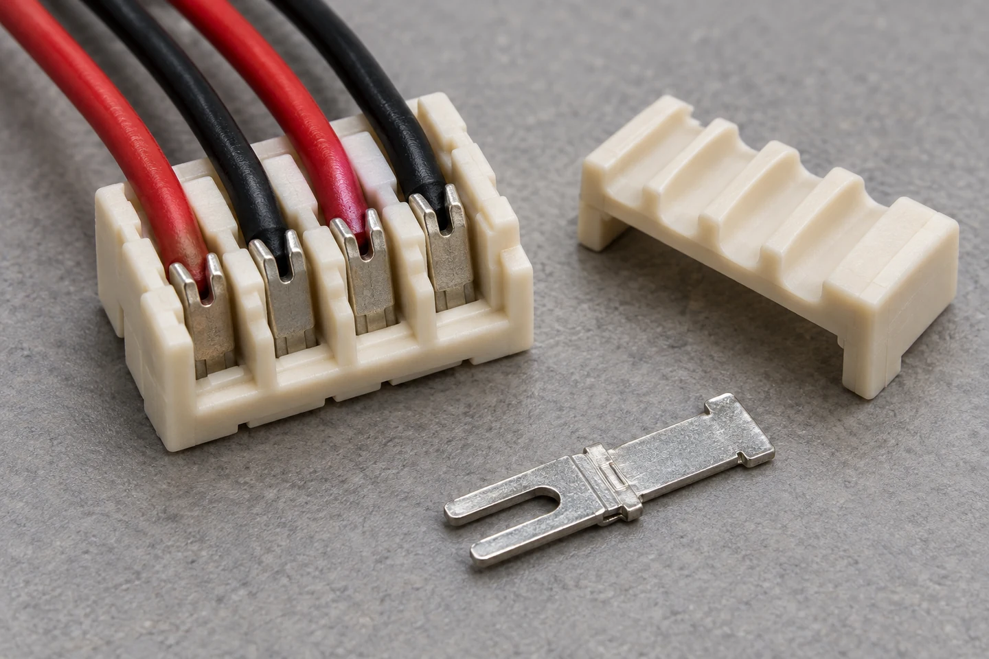
CONNECTOR ASSEMBLY / Four-position wire layout before cover assembly
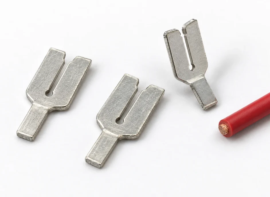
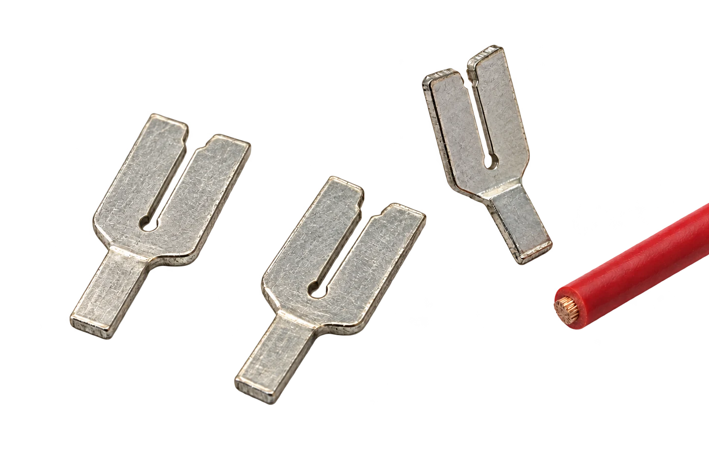
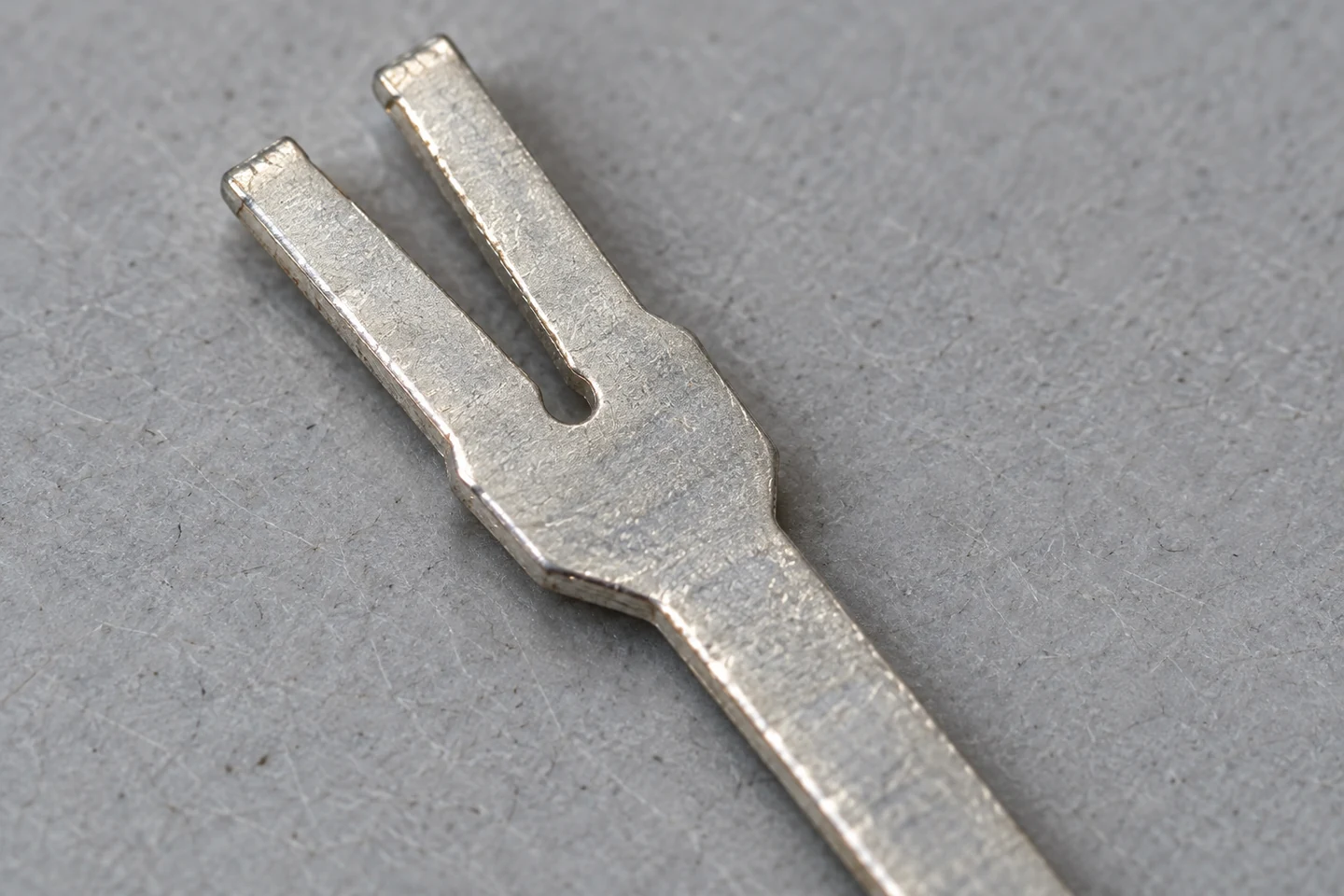
The fork entrance guides the wire toward the slot. During insertion, the slot edges displace the insulation and engage the conductor. Local conductor deformation and the contact’s elastic response establish intimate metal-to-metal regions. The objective is not simply to make the edge as sharp as possible. It is to create and maintain the intended interface when the specified wire reaches the specified position. Slot width alone cannot describe that behaviour.
An IDC termination differs from a conventional crimp, where a barrel is formed around a stripped conductor. Here, the insulated wire enters a slot. A PCB press-fit pin engaging a plated through-hole is another interface again. Insulation-piercing terminology sometimes includes IDC, but a needle or toothed penetration contact should not inherit the inspection criteria of an open-fork slot merely because both pass through insulation.
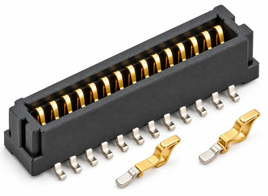
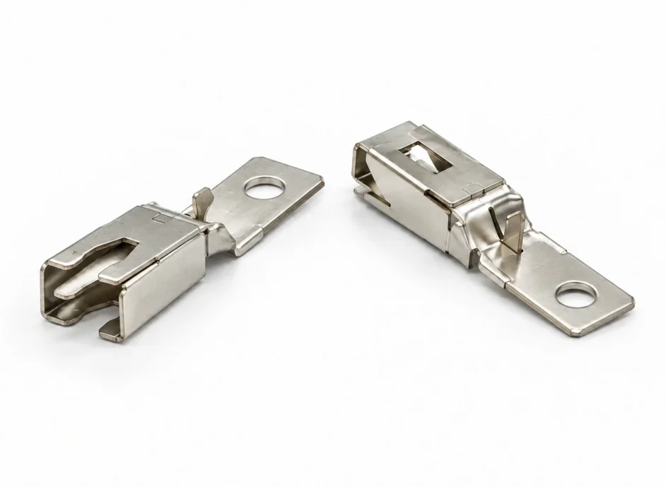
A connector may also have a mating interface that engages a pin or blade, in addition to its wire termination. These interfaces have separate geometries and functions. A firmly latched plug does not rule out a defective wire termination, and a wire that resists pullout does not establish adequate mating-contact force. Separating the inspection locations makes it possible to identify where resistance or movement originates.
Gas-tightness at the metal interface describes a local contact region. It does not establish an ingress-protection rating for the complete housing. Wiring exposed to water or oil also requires an assessment of seals, cable jacket, housing engagement and compatibility with the actual environment.
Wire selection needs to go beyond nominal cross-section or AWG. Check whether the approved conductor is solid or stranded and, for a stranded wire, review strand count, strand diameter, lay and conductor finish. Equal cross-section does not mean equal behaviour inside the slot: a bundle of finer strands can redistribute differently. Qualification with a solid conductor cannot simply be transferred to stranded wire, nor does qualification with one stranded construction cover every flexible wire.
Insulation is part of the termination process. Its outside diameter and wall thickness affect the fit through the entrance and wire guide, while material and hardness affect displacement and insertion resistance. Changing from PVC to another insulation is not merely a colour change. Even similar wire designations require a comparison of conductor construction and insulation when the supplier or product family changes.
A practical application matrix ties the terminal part number to the wire part number and revision, and to the approved tooling or applicator. Establish that combination first, then determine whether an alternative wire falls within its qualified scope. Connector colour and visual similarity are not reliable substitutes for checking the actual slot specification.
| Variable | Effect on termination | Basis for comparison |
|---|
| Conductor construction | Changes deformation, strand distribution and potential damage in the slot | Solid or stranded type, strand count and diameter, conductor material and finish |
|---|
| Insulation | Changes entry, insulation displacement and wire support | Material, outside diameter, wall thickness and specified hardness where applicable |
|---|
| Terminal and housing | The contact slot, guide and support establish wire position | Exact part numbers, drawing revisions and permitted wire list |
|---|
| Termination tooling | Changes the loading position and final seating position | Tool geometry, fixture reference, settings and approved combination |
|---|
Effect on termination · Basis for comparison
- Conductor construction
- Changes deformation, strand distribution and potential damage in the slot
- Solid or stranded type, strand count and diameter, conductor material and finish
- Insulation
- Changes entry, insulation displacement and wire support
- Material, outside diameter, wall thickness and specified hardness where applicable
- Terminal and housing
- The contact slot, guide and support establish wire position
- Exact part numbers, drawing revisions and permitted wire list
- Termination tooling
- Changes the loading position and final seating position
- Tool geometry, fixture reference, settings and approved combination
Termination begins with alignment. A wire offset from the fork centre or presented at an angle can load one side disproportionately. The fixture must support the housing or designated support surfaces, and the tool must apply force only where the product permits it. Using a sensitive mating-contact surface as an improvised locating or pressing face can damage a different interface while the wire appears properly seated.
Insertion depth is not defined solely by machine travel. The drawing establishes where the conductor must sit relative to contact and housing references, and how far the wire end must extend through the termination. Under-insertion may leave inadequate engagement; over-insertion can damage strands, spread the contact or break the housing. Inspect the finished wire-to-slot relationship against those references.
A force–displacement trace can help detect missing wire or abnormal insertion in automated assembly. Insulation, friction and tooling condition all contribute to the trace, so peak force alone is not a quality decision. Correlate process records with verified seating, appearance and sectioned samples before establishing process limits. Preparing a section also requires support that prevents cutting or polishing from moving the conductor and contact.
IDC eliminates separate stripping of individual insulation at the termination point. It does not necessarily eliminate outer-jacket removal, wire organisation or cutting to length. Reconnection is also product-specific: some systems permit a defined procedure, while others prohibit rework after termination. Pushing a suspect joint deeper or extracting and reinserting a wire should never become an improvised standard repair.
CONTACT SLOT / Conductor contact region and insertion lead-in
Cable tension, repeated bending near the exit and equipment vibration can change the condition of a termination. The IDC slot establishes electrical contact; strain relief supports insulation or cable to manage external load. These features may sit close together, but they have different inspection purposes. Deep wire seating alone does not demonstrate adequate cable support.
In a multi-position connector, neighbouring wires and the cover can conceal a problem in one cavity. Confirm that each wire follows its guide, the cover is fully engaged and the harness is not restrained in a twisted condition. An abrupt bend near the exit or a short wire pulled taut can make the installed assembly behave differently from a newly terminated sample on the bench.
A tensile test needs a defined purpose. Testing termination retention differs from testing an assembly that includes a separate cable clamp, because the load path changes. Contact retention in a housing, wire retention in a contact and connector latch retention are three different properties. Record test direction, fixture arrangement and loading conditions before comparing results.
The assembly model below separates the contacts, housing, cover and wire support. Actual assembly sequence and support geometry vary by design. The useful question is where cable loads travel in the completed product and whether unnecessary movement remains at the electrical interface.
Manufacturing control extends beyond slot width and entrance shape to sheet thickness, contact alignment, cut-edge condition and burr direction. An irregular projection in the wire path can change how insulation and conductor deform. Rounding every edge is not a solution either. Drawings and inspection criteria must distinguish an intentional functional slot edge from an unintended burr that should be removed.
The alloy designation alone does not establish long-term performance. Temper, strip orientation, geometry and operating temperature affect elastic margin and stress relaxation. A termination that begins with satisfactory contact may change under sustained heat. Conductor deformation also contributes, so a hardness measurement on the terminal alone cannot establish the service life of the joint.
Plating affects the contact interface and its corrosion and wear behaviour, but it cannot correct an unsuitable slot. The wire termination and the repeatedly mated interface may require different finishes. Gold or silver appearance is not proof of coating composition or quality. Tie the specified material, layer system, thickness and functional areas to manufacturing requirements, and protect contacts from handling contamination and unsuitable storage.
Production control must establish whether the process remains stable after tooling wears, not only whether the first sample is acceptable. Track slot geometry, final wire position and relevant process signals. A die repair, finish change or tooling replacement should trigger a review of the affected characteristics. The controlled result is the termination condition from contact manufacture through harness assembly, rather than an attractive terminal in isolation.
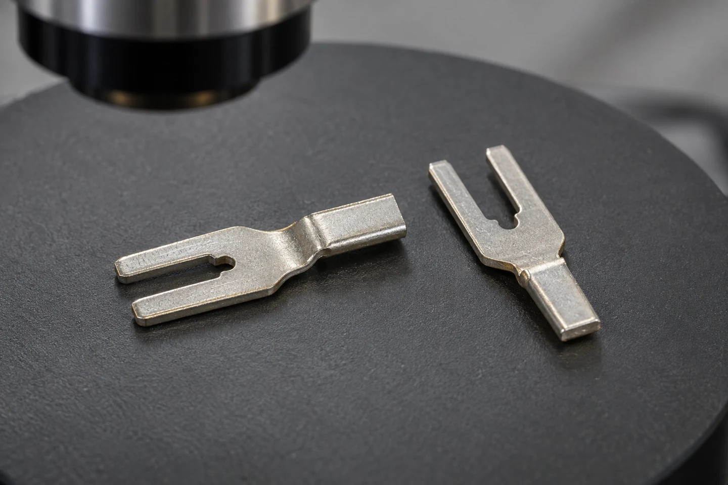
CONTACT INSPECTION / Magnified inspection of the terminal slot and form
Continuity testing is a starting point for finding wiring errors or open circuits. For precise comparison of low resistance, a four-wire measurement is useful when the current path and voltage-sensing points are defined. A measurement across the termination alone has a different meaning from one that includes wire length and the mating interface. Keep those locations consistent. Where testing must avoid altering surface films, use the voltage and current conditions required by the applicable test procedure.
Electrical stability and mechanical retention provide complementary evidence. A wire that withstands pullout does not necessarily have stable resistance, and low initial resistance does not guarantee performance after vibration. Relate temperature rise under the applicable current, ambient temperature and neighbouring-circuit heating to the condition of the termination. Compare behaviour before and after the specified thermal, humidity and vibration exposures. Where repeated micromotion is possible, assess fretting and resistance variation at the interface.
Test access also affects the procedure. Cutting a housing to reach the joint can remove the support that maintains the connection, leaving a sample that no longer represents the assembly. Define access, finished-assembly support and test sequence in advance. Allocate samples for destructive sections according to the electrical and mechanical test objectives; do not continue a qualification sequence with a specimen already damaged by another test.
Acceptance limits belong to the specific product and qualification plan. The label IDC does not justify assigning a generic current, pull-force or resistance limit, or extending one successful test to every wire and environment. Recording what must be rechecked after changes to wire or terminal supply allows design review and production quality control to use the same basis.
| Check | What it establishes | Conditions to record |
|---|
| Appearance, seating and section | Conductor position, contact or insulation damage and joint geometry | Reference surfaces, observation location, sample preparation and limits |
|---|
| Pull and cable support | Mechanical retention along the defined load path | Direction, fixture and inclusion of strain relief |
|---|
| Resistance and temperature rise | Electrical and thermal behaviour in a specified circuit and load | Sense points, wire length, current and ambient conditions |
|---|
| Before-and-after environmental tests | Changes following thermal, humidity and vibration exposure | Test sequence, sample configuration and permitted change |
|---|
What it establishes · Conditions to record
- Appearance, seating and section
- Conductor position, contact or insulation damage and joint geometry
- Reference surfaces, observation location, sample preparation and limits
- Pull and cable support
- Mechanical retention along the defined load path
- Direction, fixture and inclusion of strain relief
- Resistance and temperature rise
- Electrical and thermal behaviour in a specified circuit and load
- Sense points, wire length, current and ambient conditions
- Before-and-after environmental tests
- Changes following thermal, humidity and vibration exposure
- Test sequence, sample configuration and permitted change
Industrial IDC quality is not established by the speed of wire insertion. A matched wire and slot, repeatable seating, a supported assembly and verification under the intended operating conditions together establish the basis for a reliable connection.



 ID