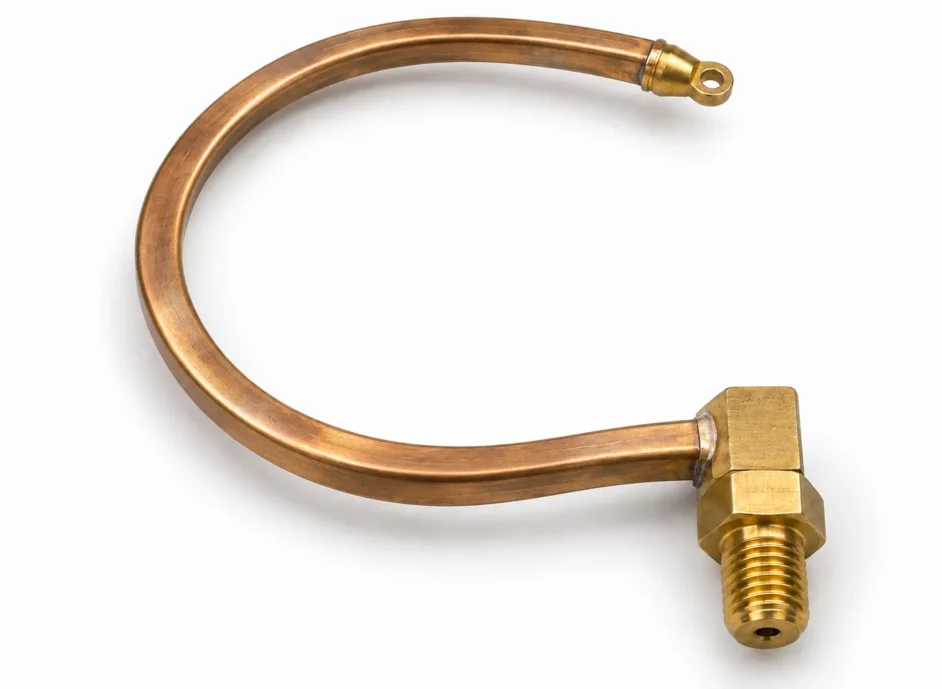
Bourdon tube brazing cannot be judged only by the appearance of a neat silver-coloured seam. Inside a mechanical pressure gauge, a thin C-shaped tube responds elastically to internal pressure. The small movement of its tip is transmitted through a link and gear mechanism to the pointer. The root where the tube meets the socket must contain pressure while remaining a stable reference for that movement.
This article focuses on a phosphor-bronze Bourdon element joined to a brass socket with a silver-based brazing filler. Other gauges use soft soldering or welding according to their materials and service conditions. Understanding the tube section, fixed and free ends, and pressure passage therefore comes before choosing a joining process. Joint clearance and thermal history can then be related to that structure, followed by joint inspection and calibration of the completed instrument.
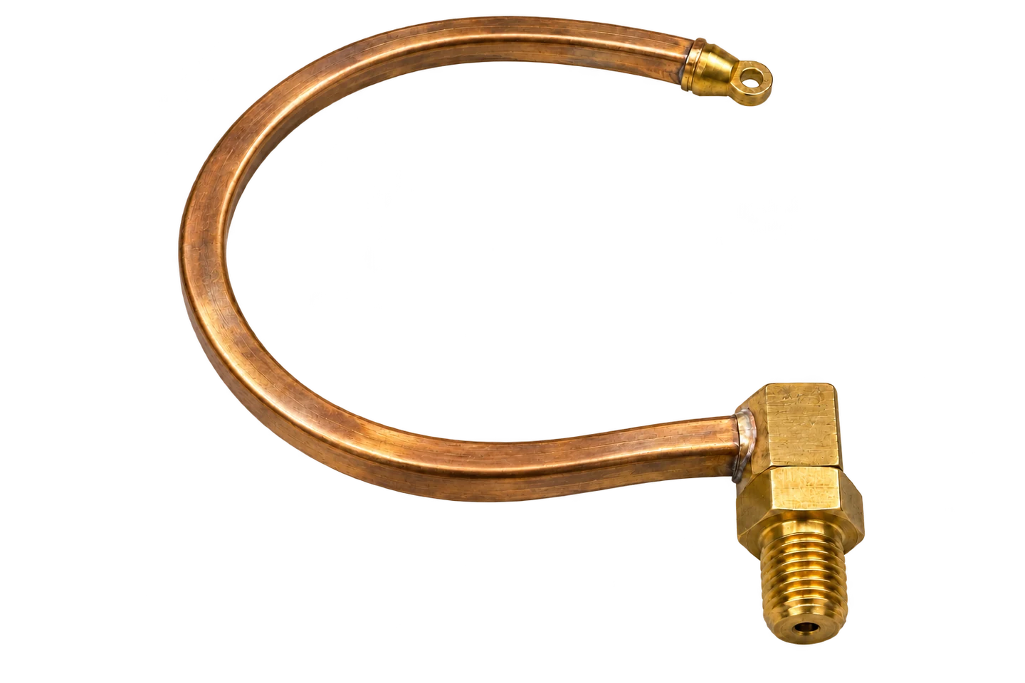
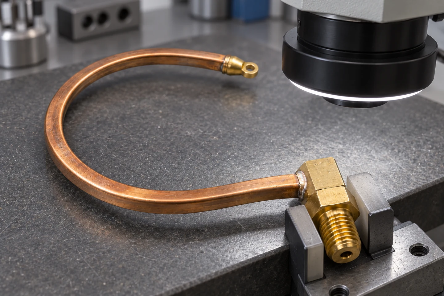
BOURDON ASSEMBLY / Joined sensing element and separate tube and socket
A C-shaped Bourdon element is not simply a round pipe bent into an arc. It is an elastic hollow tube with a flattened oval section. One end communicates with the pressure passage in the socket, while the other is sealed. The measured fluid enters through the socket but does not discharge through the free end. A tip at the sealed end provides an attachment point for the linkage.
As the pressure difference across the wall rises, the flattened section tends toward a more rounded shape. In a curved tube, cross-sectional distortion and longitudinal deformation combine to move the free end in an uncoiling direction. This is not uniform inflation of the whole tube. Section aspect ratio, wall thickness, arc geometry and material condition contribute to its response together.
The fixed root is more than a connection unrelated to the reading. Insertion depth, angular orientation and stiffness of the bonded region establish the boundary of the actively deforming element. Tubes with the same external shape can develop different tip motions when that boundary changes. Joint design must therefore consider both the length needed for sealing and the part of the tube intended to remain elastically active.
A link, sector gear and pinion amplify tip displacement into pointer rotation. Tube response and mechanism friction or backlash consequently appear together in the final indication. The 3D view below shows the pressure path and the relationship between fixed and free ends. Motion is enlarged for visibility; it does not represent a pressure-to-displacement prediction for a specified tube.
A phosphor-bronze tube silver-brazed to a brass socket is an established construction in mechanical pressure gauges. The tube undergoes repeated elastic deformation; the socket connects to the process and supports the element. Their different functions mean that membership of the same broad copper-alloy family does not justify identical material conditions or manufacturing treatment. In particular, the tube must retain the elastic behaviour developed through its forming and heat-treatment sequence.
Copper-alloy elements may also use soft-soldered joints, while stainless and nickel-alloy elements can use welded joints. Replacing soft solder with a silver-based brazing filler does not automatically improve every property. Service temperature, sustained loading, fluid compatibility and the thermal exposure tolerated by the parent metals must be considered together. Changing a qualified joining process brings both the elastic element and instrument performance back into the validation scope.
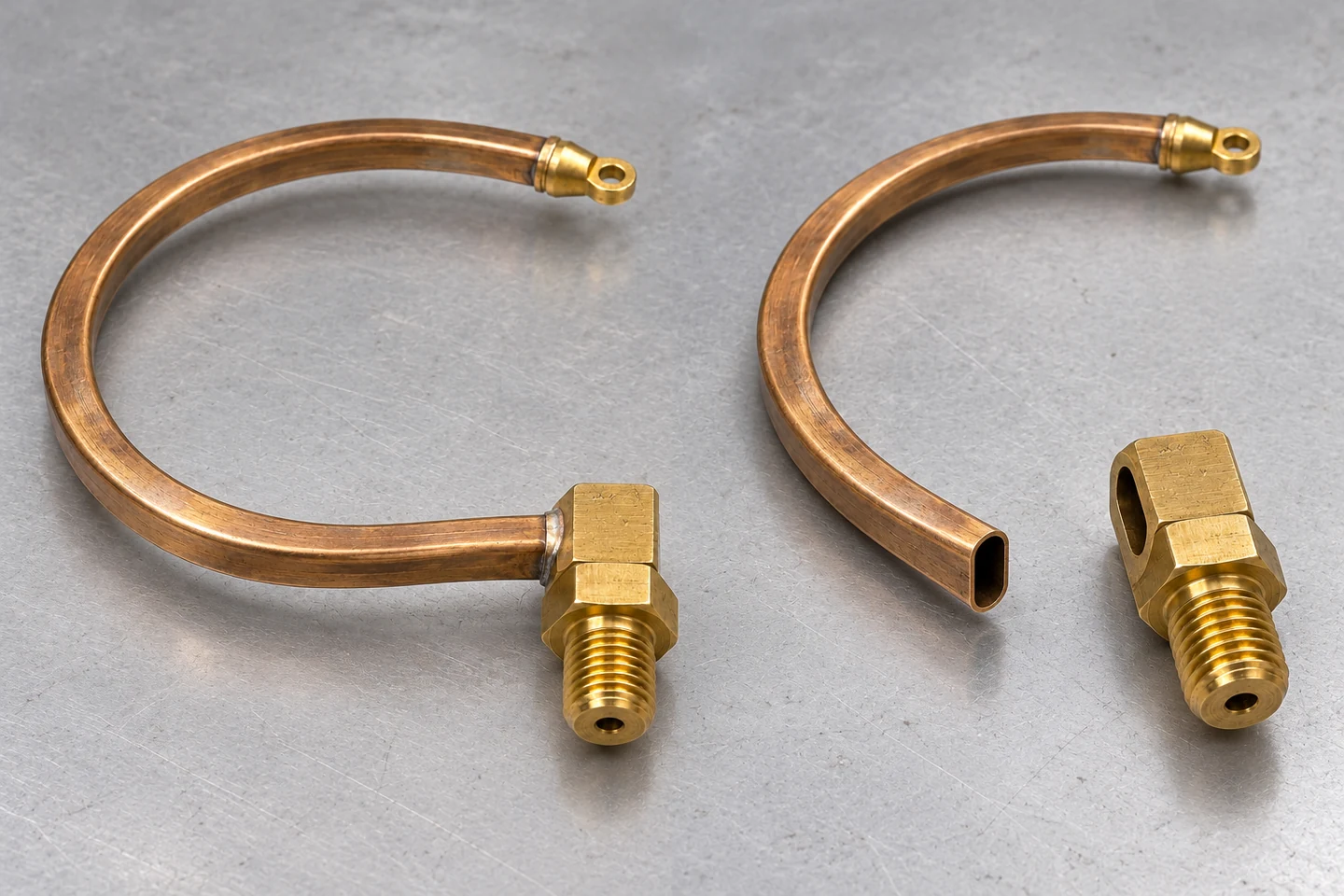
The socket entry should support the tube at its intended orientation without crushing its thin wall. In a lap joint, insertion depth changes bonded area and the length over which force is transferred. The socket mouth and abrupt section transitions also affect deformation near the root. Forcing the tube into a mechanically tight fit can alter the section and clearance before heating starts.
The fixed-root joint and the free-end closure are distinct details. Both contain pressure, but the root transfers load into the socket while the free end carries the moving linkage attachment. Filler quantity or heating practice qualified at one location cannot simply be assigned to the other. The drawing should define the materials, insertion or closure geometry, and function of each joint separately.
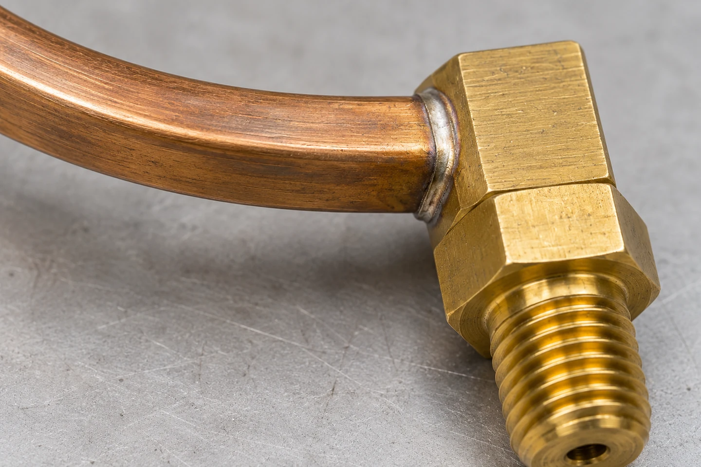
TUBE–SOCKET JOINT / Fixed tube root and socket joint
Brazing forms the joint by allowing molten filler to wet and spread between mating surfaces through capillary action, while the parent components remain solid. It needs both a connected clearance and surfaces that can be wetted. A large external fillet does not demonstrate that the internal overlap has filled adequately. The visible seam and internal fill are different observations.
A room-temperature drawing clearance does not necessarily remain unchanged during heating. Thermal expansion, temperature gradients and assembly restraint act together. A tightly closed region can obstruct filler movement, whereas an excessively open region can prevent the intended capillary fill. Rather than transferring a generic filler recommendation to every part of a flattened tube, establish the conditions for the actual section and its geometry at joining temperature.
The pressure passage must remain open while the joint clearance fills. Filler entering the lumen, or contamination left inside, can restrict the passage and change response. A tube end crushed closed inside the socket requires the same attention. Adding filler to produce a larger external bead does not solve these problems. Filler placement, quantity and the available flow paths need to be matched to the joint geometry.
During process development, sections of representative assemblies can reveal continuity of fill, the parent-metal interface, pores and excessive erosion. A single cut nevertheless shows only a limited part of the joint. Interpret sectioning together with visual and leak inspection, then reproduce the qualified fit, heating and filler delivery in production. The 3D cutaway below distinguishes the overlap that must fill from the pressure passage that must remain open.
A central difficulty in Bourdon tube brazing is the thermal difference between the components. The thin tube heats rapidly, while the socket absorbs substantially more heat. Melting filler outside the joint before the socket surface is ready can leave poor wetting on that side. Prolonged concentrated heating of the tube can compromise its elastic condition or shape. Whether heat comes from a torch or induction is less informative than the actual thermal history of each region.
The element’s forming and heat-treatment condition influences hysteresis and return behaviour. Heat effects should therefore not be judged by surface discoloration alone. Consider tube orientation, permanent distortion and changes between increasing- and decreasing-pressure response. Where lowering joining temperature alone cannot resolve the issue, filler selection, joint geometry, heat-source placement and process sequence need to be adjusted together.
A fixture should maintain orientation without squeezing the thin wall or changing its oval section. Its location and contact area also affect heat extraction from the socket. Consistent seating and thermal conditions reduce variation caused by where an operator holds the assembly. This supports control of the cooled geometry as well as the brief period during which filler flows.
Cleaning and oxidation control establish the conditions for wetting. Flux or protective atmosphere must suit the parent metals, filler and heating method. After joining, residues must not remain in the lumen or inaccessible crevices. Cleaning for a bright external appearance does not necessarily clean the pressure passage. The process should also account for how cleaning affects the thin tube wall and other assembly materials.
| Process element | Role at the joint | Connection to measurement |
|---|
| Fit and insertion depth | Define overlap and filler-flow clearance | Retain root position and the active-element boundary |
|---|
| Heat source, duration and fixture | Control temperature distribution | Limit distortion and response changes |
|---|
| Filler placement and quantity | Establish a continuous joint | Avoid obstruction of the internal passage |
|---|
| Oxidation control and cleaning | Support wetting and remove residues | Manage passage cleanliness and corrosion risk |
|---|
Role at the joint · Connection to measurement
- Fit and insertion depth
- Define overlap and filler-flow clearance
- Retain root position and the active-element boundary
- Heat source, duration and fixture
- Control temperature distribution
- Limit distortion and response changes
- Filler placement and quantity
- Establish a continuous joint
- Avoid obstruction of the internal passage
- Oxidation control and cleaning
- Support wetting and remove residues
- Manage passage cleanliness and corrosion risk
Visual inspection considers wetting and seam continuity, tube crushing, overheating or excessive parent-metal damage, and assembly orientation. It is useful for detecting visible departures but does not directly prove leak tightness. Conversely, a result showing no detected leakage does not establish bonded area, cyclic life and indication accuracy at the same time.
Leak inspection uses a defined medium, pressure, hold time and detection method. Pressure-proof evaluation has a separate purpose, and its pressure and permitted deformation must come from the applicable design and product requirements. Surviving one elevated-pressure exposure is not evidence of endurance under repeated operation. Permanent deformation introduced during testing may remain visible in zero return and the subsequent calibration response.
Calibration of the completed gauge compares indication at the same reference-pressure points on increasing and decreasing pressure. Differences between the two directions provide information about hysteresis. Zero return after unloading helps identify permanent changes or mechanism behaviour. Observe smooth pointer travel as well as readings at the selected points; hesitation or sudden jumps provide useful diagnostic information.
When a departure appears, separate changes in the element from those in the movement before correcting pointer position. An altered fixed root, a changed tube response and a shifted or frictional linkage are different causes. Linking element-assembly geometry records to completed-gauge calibration results makes the effects of a joining-process change easier to trace.
JOINT INSPECTION / Socket held for visual examination of the joint
Repeated pressure produces fluctuating stress in the elastic tube and its root. Internal surface defects, local wall-thickness variation and damage near the joint can affect cyclic life. Dressing the external seam cannot substitute for control of the lumen and root region. The potential introduction of defects needs to be followed from incoming material through forming, joining and cleaning.
The measured fluid and service temperature act on the socket, filler and residues as well as the tube. An unsuitable material combination or unremoved residue can degrade a joint that was initially leak tight. When service changes, reassess the actual wetted materials, joining method and temperature conditions rather than relying on a familiar alloy name. Thermal effects in brazed and welded constructions must be interpreted in their respective material and process contexts.
For production, the ability to repeat the same fit and thermal history matters more than one satisfactory sample. Link the element’s forming and heat-treatment history, socket-entry dimensions, filler and oxidation-control conditions, fixtures and heating records to product identity. A changed condition should permit comparison of calibration response as well as appearance and leakage. Acceptance criteria should follow the service requirements instead of assigning universal cycle counts or allowable leakage figures.
Manufacturing review consequently needs more than an outline drawing. Tube section and wall thickness, arc and insertion geometry, material condition, pressure, temperature, fluid, required accuracy and cycling conditions jointly define the joining task. Components with similar external appearances do not necessarily deliver the same response. Both drawing review and physical comparison must include the measurement function.
| Verification | Property examined | Conditions to retain |
|---|
| Visual, dimensional and development sections | Orientation, fill and damage | Geometry, observation location and manufacturing history |
|---|
| Leak and pressure-proof tests | Containment under defined conditions | Medium, pressure, duration, method and acceptance limits |
|---|
| Increasing/decreasing calibration | Indication error, hysteresis and zero return | Reference points, environment and mounting position |
|---|
| Cycling and environmental assessment | Performance changes under service-related conditions | Pressure history, temperature, fluid and before/after results |
|---|
Property examined · Conditions to retain
- Visual, dimensional and development sections
- Orientation, fill and damage
- Geometry, observation location and manufacturing history
- Leak and pressure-proof tests
- Containment under defined conditions
- Medium, pressure, duration, method and acceptance limits
- Increasing/decreasing calibration
- Indication error, hysteresis and zero return
- Reference points, environment and mounting position
- Cycling and environmental assessment
- Performance changes under service-related conditions
- Pressure history, temperature, fluid and before/after results
Bourdon tube brazing must do more than attach a thin tube firmly to a socket. It must preserve a sealed pressure boundary, the elastic element’s geometry, an open passage and a stable fixed-root condition. Relating joint quality to increasing- and decreasing-pressure response and zero return allows this small, often hidden joint to be managed as part of a measuring instrument.



 ID